Table of Contents
Advertisement
Advertisement
Table of Contents

Summary of Contents for Supratec S200
- Page 1 S200 Open User Manual User Manual S200 Open Update April 2018...
- Page 2 00011- RCS (Trade & Corporate Register) Créteil – NAF (Business subsector ID number) 2651B - Intra-Community VAT: FR 91 499665230 www.aqualabo.fr Hotline: +33 (0)5.62.75.95.70 E-mail: info@aqualabo.fr Website: www.aqualabo.fr Subject to technical amendments. Errors and omissions excepted. User Manual S200 Open Update April 2018...
-
Page 3: Table Of Contents
7.1 OPTOD digital optical sensor for measuring dissolved oxygen ........21 7.1.1 Reminder of connection to the terminal: ..............21 7.1.2 Setting / configuring of displayed measurements ............21 7.1.3 Sensor information ....................23 User Manual S200 Open Update April 2018... - Page 4 8.7.7 Dosage monitoring ....................41 8.8 Manual operating mode ....................41 8.8.1 Manual controller mode ..................... 41 8.8.2 Automatic controller mode ..................42 8.9 Date and time ........................42 8.10 Analog outputs ......................42 User Manual S200 Open Update April 2018...
- Page 5 12.1 Shielding ........................49 12.2 Communication parameters ..................49 12.3 MODBUS functions used ....................49 12.4 MODBUS S200 registry list ................... 50 13 Sensor - Actuator bus (MODBUS RTU) ................51 13.1 Shielding ........................51 13.2 Communication parameters ..................51 14 Appendix ..........................
- Page 6 17 Hotline-Aftersales Service contact details ................56 User Manual S200 Open Update April 2018...
-
Page 7: General Information
1 General information 1.1 General overview This technical manual contains instructions for installing, commissioning, maintaining and repairing the S200 Open measurement and monitoring device. Please follow the safety instructions and notes in bold print at all times! 1.2 Notes in bold print... -
Page 8: Electrical Connection
1.4 Electrical connection Warning: Only use the power supply specified on the nameplate to run the S200 measurement and monitoring device! The device is delivered to run, by default, on a 230V/50Hz or 110V/50Hz power supply. 1.5 Safety Instructions S200 Open measuring and monitoring devices are manufactured and tested according to standards DIN EN 61010-1 / VDE 0411-1. -
Page 9: Technical Data
Permissible storage temperature -20°C to +65°C Permissible humidity Max. 90% to +40°C (non- condensing) Device dimensions 166 x 161 x 73.5 mm (l x h x d) Weight Approx. 1.1 kg Warning: Unit fuse of 16A max. User Manual S200 Open Update April 2018... -
Page 10: Variable Measurements
ModBus digital sensor: 0.1 mg/l and 1%. 0% to 200% Turbidity 0.00 to 50.00 NTU ModBus digital sensor from 0.01 to 1 NTU. 0.0 to 200.0 NTU 0 to 1,000 NTU 0 to 4,000 NTU User Manual S200 Open Update April 2018... -
Page 11: Description
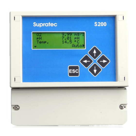
3 Description The S200 Open measuring and monitoring device is easy to use. Equipment: • Backlit display • Cursor-controlled operation with only 5 keys • Browser menu in plain text • Up to 6 different settings simultaneously (depending on the type of code) •... -
Page 12: Operation
Display Backlit LCD screen with 4 lines of 20 characters each Cursor control/Numerical value increase Choice confirmation/Function change Cursor control/Numerical value decrease Choice of operating menu Value backup/Return to level 1 menu Cancel input without saving/Return to the home screen. User Manual S200 Open Update April 2018... -
Page 13: Display
Indicates that the cursor can be moved up or down using the cursor keys. → The additional arrow on the right indicates that a sub-menu or input of numeric values can be selected. User Manual S200 Open Update April 2018... -
Page 14: General Menu
From the main screen (real-time display of measurements), the DOWN arrow gives access to the General menu. The list of items accessible from the General menu is as follows: Calibration ↕→ Temp. Compens./ Controller setting Manual mode Time / date Basic settings Service User Manual S200 Open Update April 2018... -
Page 15: Example Of Access To A Sub-Menu, Selection Of "Temperature Compensation" Menu15
If the temperature is compensated automatically, Pt100 / Pt1000 is used. Temp. Compens./ ↕→ Automat. Comp. Default temp. 25.0°C Use the … key to select the settings input. User Manual S200 Open Update April 2018... - Page 16 This indicates that the cursor key - left arrow - is used to complete the input and the value is saved. Note: The information entered can be canceled at any time by pressing key. The old value is retained. User Manual S200 Open Update April 2018...
-
Page 17: Installation
Digital output for electronic monitoring Max. load 200 mA / 30V Dosing pumps Switching from output relay 1 80+81 Potential-free contact Switching from output relay 2 82+83 Potential-free contact Switching from output relay 3 84+85 Potential-free contact User Manual S200 Open Update April 2018... - Page 18 12VDC power supply voltage 93 = A, communication Modbus RS485 interface 12 V DC max. 200 mA 94 = shielding 95+96+97 95 = B for communication with 96 = A 97 = shielding management system User Manual S200 Open Update April 2018...
-
Page 19: Access And Display
Note: It may not be possible to adjust the contrast too high or too low. Please adjust the contrast as follows: Press the key in, keep it in while pressing to increase contrast. User Manual S200 Open Update April 2018... -
Page 20: Adjusting The Backlight
6.3 Displa y - Loss of communication If communication with a Modbus RS485 digital sensor is lost, the parameter display, e.g. oxygen in mg/L for an OPTOD sensor, will flash until communication is restored. User Manual S200 Open Update April 2018... -
Page 21: Use Of Measurements Provided By A Modbus Rs485 Sensor
The operator has access to the range of parameters from a digital sensor such as the OPTOD from the BASIC SETTINGS sub- menu. Calibration Temp. Compens./ Controller setting Manual mode Time / date Basic ↕→ settings Service User Manual S200 Open Update April 2018... - Page 22 In this case, the temperature or oxygen will be selected as these 2 parameters are delivered by the OPTOD sensor. Parameter 1 Oxygen dig. sensor ↕→ Note that these two parameters can be viewed simultaneously by configuring parameters 1 and Parameter 2 Temp. measurement ↕→ User Manual S200 Open Update April 2018...
-
Page 23: Sensor Information
The operator has access to information on the connected sensor from the main SERVICE menu. Manual mode Time / date Basic settings Service ↕→ Display setting Device data Analog inputs Oxygen dig. sensor ↕→ User Manual S200 Open Update April 2018... -
Page 24: Oxygen Measurement Configuration
The sensor does not have this information for the other two parameters: salinity and atmospheric pressure. They must therefore be provided by the S200 Open device. The BASIC ADJUSTMENT submenu, from the main menu, provides access to the oxygen digital sensor configuration. -
Page 25: Calibration Methods
7. 1. 5 Ca lib r at i on m ethod s The S200 Open offers two calibration methods, as a saturation %, for the oxygen probe: • Calibration of the final value (calibration at one point – 100%) This method allows the probe to be calibrated quickly. -
Page 26: One-Point Calibration Sequence
A sodium sulfite solution (concentration < 2 % by weight) is used as the zero point calibration solution for the two-point calibration sequence. The general condition of the sensor must be checked before starting the sequence. User Manual S200 Open Update April 2018... -
Page 27: Calibration Of Zero Point - Detailed Procedure
Reading 0.1 % Calibr. 0.0↕% → ← Calibr. 100.0 % 7. Pressing the right and left arrows simultaneously will start the measurement sequence. 2-point Calibr. Reading 0.1□% Calibr. 0.0↕% →← Calibr. 100.0 % User Manual S200 Open Update April 2018... -
Page 28: Calibration Of The Final Point - Detailed Procedure
This display turns off when the calibration is complete. Once the two-point calibration sequence is complete, pressing the DOWN arrow displays the coefficients, zero point and slope, calculated by the sensor during both stages. User Manual S200 Open Update April 2018... -
Page 29: Error Calibration - Message
If, however, due to a manipulation error, the calibration sequence led to the creation of erroneous coefficients, a message to that effect will be repeated on the main screen. The main screen then displays: 1.12 mg/l °C 23.10 °C Error Calibr. ↓ User Manual S200 Open Update April 2018... -
Page 30: Digital Sensor For Measuring Nephelometric Turbidity
The sensor is calibrated in the factory, so there is no need to perform calibration during initial commissioning. The sensor shall be cleaned at regular intervals, during operation, depending on the level of contamination of the liquid studied. User Manual S200 Open Update April 2018... -
Page 31: Setting / Configuring Of Displayed Measurements
… Selecting one of the six parameters leads to a list of choices: - No measurement - Temperature measurement - Turbidity measurement - Oxygen digital sensor - MES-Turb. measurement - pH digital sensor. User Manual S200 Open Update April 2018... - Page 32 The temperature value from the turbidity sensor is displayed after activation in the TEMP. COMPENS. menu. Default temp. ↕→ 25.0°C Choose sensor Turbidity The main screen then displays: °C 23.10 °C Man→ ↓ User Manual S200 Open Update April 2018...
-
Page 33: Sensor Information
The first RANGE line on this screen is used to select the range of measurement from among the 4 available: 0-50; 0-200; 0-1,000 or 0-4,000 NTU Turbidity meas. Range 0-50 NTU ↕→ Temperature measurement 23.27°C User Manual S200 Open Update April 2018... -
Page 34: Method For Calibrating Nephelometric Turbidity
Note: After selecting the measurement range and in the event of excess when the S200 Open device returns to Measurement Mode, the measurement will remain frozen on the screen. In this case, and if the measurement remains frozen, return to the measurement range selection menu to choose a wider range. - Page 35 Use the UP arrow to adjust the digital display to the value of the aqueous formazine suspension used, for example, 100.0 NTU. Once the suspension is perfectly uniform, pressing the right and left arrows simultaneously will start the measurement sequence. User Manual S200 Open Update April 2018...
- Page 36 This display turns off when the calibration is complete. Once the two-point calibration sequence is complete, pressing the DOWN arrow displays the coefficients, zero point and slope, calculated by the sensor during both stages.. Zero-Point 0.00 NTU Slope 2.01 % ↑ User Manual S200 Open Update April 2018...
-
Page 37: Controller Adjustments
For example, REDUCE indicates that the controller is running when the value is greater than the pre-determined set point. As a result, the value decreases (lower value). 8.3 Assignment of controller output The controller output signal may be assigned to various actuators (relay, etc.). User Manual S200 Open Update April 2018... -
Page 38: Pulse Frequency
10 sec., in this case, it would return to 5 seconds. A controlled variable of 0 % indicates no pulse. A controlled variable of 100% indicates no interval. Pulse frequency 100* 36 P/h Pulse interval ↕→ User Manual S200 Open Update April 2018... -
Page 39: Minimum Pulse
The right arrow gives access to the setting details. The example described below represents the temperature parameter. Set point 0.0°C ↕→ P-range 0.0°C Each item can be changed, right arrow then up or down, to set a numerical value. Set point 1.5°↕C ← P-range 0.0°C User Manual S200 Open Update April 2018... -
Page 40: Standard Point Adjustment
8. 7. 4 H yst er e si s If the controller is used like an ON/OFF controller, the hysteresis parameter can be used to adjust a default dead band around the set point. User Manual S200 Open Update April 2018... -
Page 41: Max./Min. Limit Value
The preset monitoring type for the controller is used for monitoring, pulse frequency or pulse intervals. For example, the action of a single, normally open relay is managed in manual mode, by adjusting to 100% for a period of X minutes when closed. User Manual S200 Open Update April 2018... -
Page 42: Automatic Controller Mode
Year 8.10 Analog outputs The S200 measurement and monitoring device enables all measurement values to be output as standard current signals of 0/4-20mA according to standard DIN IEC 60381-1. You can adjust the output type at this location. BASIC ADJUSTMENT has to be chosen from the main menu and then ANALOG OUTPUT. -
Page 43: Assignment Of Measured Values
↕ → 0/4mA = 0.00°C 20 mA = 14.00°C 8. 1 0. 3 S ett i ng t he ran ge Temp. measurement Range 0-20mA 0/4mA = 10.00°C ↕→ 20 mA = 30.00°C User Manual S200 Open Update April 2018... -
Page 44: Power On Delay
8. 1 2. 3 M easu re m ent fr om a digi ta l s ens o r For example, as the device is associated with a digital nephelometric turbidity sensor, this TURBIDITE MEASUREMENT submenu provides: • Serial number User Manual S200 Open Update April 2018... -
Page 45: Deleting Data / Return To Factory Settings
The DELETE DATA menu allows you to restore the factory settings (reset). Pressing the down and right arrows simultaneously resets the device. 8.13 Languages The language is chosen in the BASIC SETTING / LANGUAGES sub-menu. User Manual S200 Open Update April 2018... -
Page 46: Initial Commissioning
Note that the BASIC SETTING submenu is accessible only after you have entered the Level 3 code, see CODES paragraph. Refer to the specific paragraphs, using the contents, to define the read and displayed parameters, as well as the entire configuration of the controller, analog outputs, etc. User Manual S200 Open Update April 2018... -
Page 47: Maintenance And Servicing
Be sure to use only a damp cloth to clean the casing. The use of strong, caustic or abrasive cleaning agents (acid cleaners, etc.) is not recommended! The S200 measurement and monitoring device is easy to service, but ensure that a qualified technician checks it and performs maintenance at regular intervals. -
Page 48: Alarm Messages
" monitoring time. Delayed start-up Start-up of the controller will be Turning on the S200 power supply " delayed for the set period of time The controller is stopped External stop of the Digital input 1 of terminal 21/22 has... -
Page 49: Modbus Rtu
12 MODBUS RTU The S200 measurement and control device is equipped with a Modbus RTU interface. This piece of equipment has an RS 485 interface. Shielding = Terminal 97 A = + Terminal 96 B = - Terminal 95 12.1 Shielding The use of shielded cables provides high protection against electromagnetic interference, especially high frequencies. -
Page 50: Modbus S200 Registry List
12.4 MODBUS S200 registr y list Registry Description Unit Range of values Position decimal point pH measuring value -200…1,600 xx.xx ORP measuring value -1,500/+1,500 xxxx POT Measurement - Measurement mg/L 0.500 xxx.x Temperature value measurement °C -3,000…14,000 xxx.xx Measurement Conductivity measurement µS mS... -
Page 51: Sensor - Actuator Bus (Modbus Rtu)
13 Sensor - Actuator bus (MODBUS RTU) The S200 measurement and monitoring device is equipped with a sensor - actuator bus. The Modbus RTU protocol is used. This piece of equipment has an RS 485 interface. Shielding = Terminal 94... -
Page 52: Appendix
14.2 Battery The S200 measurement and monitoring device is equipped with a battery so that the internal clock continues to operate even when there is no power supply. The battery must be replaced if, for example, the date or time changes abruptly (lithium battery CR 2032) Fig. -
Page 53: Spare Parts And Wear Parts
15 Spare parts and wear parts 15.1 Wear parts Article Reference CR 2032 type battery User Manual S200 Open Update April 2018... -
Page 54: Electrical Connection
Analog output 2 0/4...20 mA (500Ω load) Digital output 1 max. 200mA / 30V e.g. For monitoring a membrane metering pump Digital output 2 max. 200mA / 30V e.g. For monitoring a membrane metering pump User Manual S200 Open Update April 2018... -
Page 55: User Manual S200 Open
Relay 1 Relay 2 Relay 3 Power supply for bus devices + 12 V 12V DC 200mA Sensor - Actuator - Bus 2. RS 485 Interface (Modbus RTU) 1. RS 485 Interface (Modbus RTU) User Manual S200 Open Update April 2018... - Page 56 17 Hotline-Aftersales Service contact details AQUALABO ZA de Bellevue 115 Rue Michel Marion 56850 CAUDAN FRANCE 5.62.75.95.70 Hotline: +33 (0) User Manual S200 Open Update April 2018...
Need help?
Do you have a question about the S200 and is the answer not in the manual?
Questions and answers