
Subscribe to Our Youtube Channel
Related Manuals for Edco TLR-7

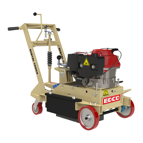
Summary of Contents for Edco TLR-7
- Page 1 TLR-7-I-0715 E-SPTS-I-0809 EQUIPMENT DEVELOPMENT CO., INC. Operator’s Instruction Manual TLR-7 TRAFFIC LINE REMOVER EQUIPMENT DEVELOPMENT CO., INC. www.discount-equipment.com...
- Page 2 TLR-7-I-0715 EQUIPMENT DEVELOPMENT CO., INC. READ AND UNDERSTAND THE OPERATORS INSTRUCTION MANUAL THOROUGHLY BEFORE ATTEMPTING TO OPERATE THIS EQUIPMENT. Death or serious injury could occur if this machine is used improperly. SAFETY SAFETY MESSAGES • Do not disconnect power by pulling cord. To disconnect, grasp the plug, not the cord.
-
Page 3: Safety Guidelines
Death or serious injury can result if this machine is used improperly. Safety Guidelines Eye and ear protection must be worn at all times while the TLR-7 is in use. During normal operation, sound pressure levels less than 85dBA. Use only ANSI approved safety glasses to help prevent eye injury. -
Page 4: Table Of Contents
Specifi cations & dimensions are for HOW TO ORDER REPAIR PARTS reference only and subject to change. To insure product safety and reliability, always use genu- ine EDCO replacement parts when making repairs to the Length (L) 49” 125 cm equipment. -
Page 5: Operating Controls
Moving the machine side to side while pushing or pulling achieves the feathered edges that weather quickly and blend with the undisturbed road surface. Do not use the TLR-7 for any purpose other than that for which it was designed. Do not modify the machine. Figure 2 Before Starting: •... -
Page 6: Operating Instructions
The surface must be level for safe operation. engaging lever is disengaged it will be resting (See fi gure 9) against the top plate of the handlebars. (See fi gure 4) 11. MOVE TLR-7 • Into position where work will be performed. 4. THROTTLE LEVER •... - Page 7 FLOATING HEAD FEATURE 15. PRESSURE CONTROL ADJUSTMENT The TLR-7 is designed to allow the cutter to fl oat • The last adjustment is the pressure control adjust- during removal operation. Maximum movement is 3/4”.
-
Page 8: How To Change The Cutters
TLR-7-I-0715 EQUIPMENT DEVELOPMENT CO., INC. INSTRUCTIONS TO CHANGE CUTTERS Figure 18 Figure 17 6. PULL RETAINING CLEVIS PIN 1. STOP ENGINE • Pull retaining clevis pin free. (See fi gure 20A & 20B) • Stop engine and disconnect the spark plug lead. - Page 9 TLR-7-I-0715 E-SPTS-I-0809 EQUIPMENT DEVELOPMENT CO., INC. INSTRUCTIONS TO CHANGE CUTTERS 6. DEPTH CONTROL KNOB 9. CUTTERS • Grasp depth control knob and lift (See fi gure 25A & • Remove, change, or replace cutters. 25B). Entire depth control assembly should move up freely allowing lower linkage to lift clear of inner 10.
-
Page 10: Maintenance
TLR-7-I-0715 EQUIPMENT DEVELOPMENT CO., INC. Read and follow Repairs are to be done instructions in the engine by authorized EDCO owner’s manual. Dealers only. Maintenance Disconnect the power source at the machine before performing any maintenance. • All maintenance should be performed regularly and by qualifi ed personnel only. -
Page 11: Smi Dust And Silica Warnings
TLR-7-I-0715 E-SPTS-I-0809 EQUIPMENT DEVELOPMENT CO., INC. SMI Dust and Silica Warning Grinding/cutting/drilling of masonry, concrete, metal and other materials can generate dust, mists and fumes containing chem- icals known to cause serious or fatal injury or illness, such as respiratory disease, cancer, birth defects or other reproductive harm. -
Page 12: Notes
Wacker, Sakai, Snorkel, Upright, Mi-T-M, Sullair, Neal, Basic, Dynapac, MBW, Weber, Bartell, Bennar Newman, Haulotte, Ditch Runner, Blaw-Knox, Himoinsa, Best, Buddy, Crown, Edco, Wyco, Bomag, Laymor, Terremite, Barreto, EZ Trench, Takeuchi, Basic, Bil- Jax, Curtis, Gehl, Heli, Honda, ICS/PowerGrit, Puckett, Waldon, ASV, IHI, Partner, Imer, Clipper, MMD, Koshin, Rice, Gorman Rupp, CH&E, Cat Pumps, Comet, General Pump,...
Need help?
Do you have a question about the TLR-7 and is the answer not in the manual?
Questions and answers