Table of Contents
Advertisement
Quick Links
Advertisement
Table of Contents

Summary of Contents for PerkinElmer EnVision
- Page 1 INSTRUMENT MANUAL 2104-9030-02 March 2008 ™ EnVision Multilabel Reader...
- Page 3 2104 EnVision ™ Multilabel Reader Valid for instruments with software version 1.12 PerkinElmer Life and Analytical Sciences, Wallac Oy, P.O. Box 10, FIN-20101 Turku, Finland. Tel: 358-2-2678111. Fax: 358-2-2678 357. Website: www.perkinelmer.com...
- Page 5 Installation and service must be performed by personnel properly trained and authorized by PerkinElmer Life and Analytical Sciences. Failure to follow these instructions may invalidate your warranty and/or impair the safe functioning of your equipment.
-
Page 7: Table Of Contents
Contents Contents Introduction..........................3 Conventions used........................4 Functional description ......................7 Application information......................7 Reporter gene assays ......................7 Enzyme assays........................7 Time-resolved fluorometry....................7 Receptor ligand binding assays ................... 7 Cellular assays........................8 Genotyping assays....................... 8 Image FlashPlate™ assays ....................8 AlphaScreen assays ...................... - Page 8 Quick start guide........................37 On-line help .......................... 37 Routine maintenance ......................37 Warnings..........................38 Report on laser safety: EnVision with the TRF laser option ..........39 General: ..........................39 Outer covers and openings of EnVision ................39 Safety switches and lid locking .................... 41 Laser beam path........................
- Page 9 Fluorescence intensity performance with monochromators..........73 Other optional modules ......................73 Measurement time and performance ..................73 DECLARATION OF CONFORMITY FOR CE-MARKING.......... 79 WEEE Instructions for PerkinElmer Products ..............81 Glossary ...........................85 Installation ..........................97 Environment ......................... 97 1. Unpacking instructions ..................... 97 2.
- Page 10 Trademarks Wallac. LANCE, FP and EnVision are trademarks and PerkinElmer, AlphaScreen and DELFIA are registered trademarks of PerkinElmer, Inc. Windows, Windows XP and Windows Vista are registered trademarks of Microsoft Corp. in the U.S. and other countries. Pentium is a registered trademark of Intel Corporation.
- Page 11 Chapter 1 Introduction...
-
Page 13: Introduction
A model with an external laser provides enhanced time-resolved fluorescence capabilities for TRF, LANCE and HTRF. EnVision is a very compact, small footprint bench top unit with features such as shaking, reading from above or below and scanning. Also available are a dispenser with up to two pumps and temperature control of the instrument chamber. -
Page 14: Conventions Used
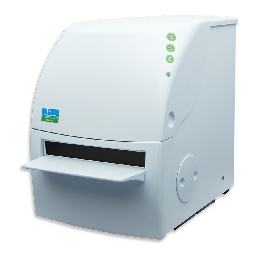
Figure 1. Wallac EnVision with a stacker Figure 2. Wallac EnVision without a stacker Wallac EnVision is designed to be customizable to suit your specific application needs without you having to invest in features you do not want. If in the future you wish to add new features, this is also possible. - Page 15 Chapter 2 Functional description...
-
Page 17: Functional Description
When you need to measure either the level of expression or the functional effect of a drug candidate in terms of transcriptional activity of cells, EnVision provides the features you need for reliable detection of reporter gene expression. The instrument has comprehensive and versatile scanning and kinetics capabilities. -
Page 18: Cellular Assays
Functional description Cellular assays Reading from below, scanning and kinetics are some of the features that make Wallac EnVision the ideal tool for cellular assays such as cAMP, + or any ADME/tox assays. The temperature control option further enhances these possibilities. -
Page 19: Technologies
Functional description Technologies The instrument uses the following measurement technologies if the appropriate options are installed: Time-resolved fluorescence (TRF) (240-850 nm) • Multiple time window TRF • Simultaneous dual emission measurements above or below • Sequential dual emission measurements above or below •... -
Page 20: Mechanical Design Overview
Functional description Mechanical design overview Figure 3. Layout of modules in EnVision (side view) 1. Case frame 19. Photometric detector 2. Front panel 20. Mirror module 3. Loading door 21. Light director assembly 4. Height sensor 22. Bottom excitation cable 5. -
Page 21: Temperature Control
Functional description Note! The optional dispenser unit is bolted on to the side of main instrument and connections made through an opening in the instrument case Temperature control The temperature control option consists of heating elements. These are located above and below the measurement position. Plate types All types of microtitration plate may be measured. -
Page 22: Optical System
Different kinds of robots can be used as the main system in an automated HTS laboratory. When used with a robot, EnVision is usually linked through COM interfaces. These provide the basis for seamless integration and instrument control. The robot and the counter work as a unit. -
Page 23: Luminescence Mode
Functional description Note! With AlphaScreen a special dichroic mirror module is used to direct the excitation laser light into the sample well. The emission path and detection is similar to that for fluorescence intensity. Luminescence mode When a luminescence sample is measured, no excitation components are used. -
Page 24: Ultra Sensitive Luminescence Mode
Functional description Ultra Sensitive luminescence mode Figure 7. Ultra Sensitive luminescence measurement Ultra Sensitive luminescence uses a very high sensitivity luminescence PMT as the detector. It has extremely low background, high dynamic range and spectral response from 300 nm up to 650 nm. The detector has no optical components and the emission light is collected directly from the well. - Page 25 Functional description dichroic mirror is about three times higher than with a general mirror module. Figure 8. Excitation from above/Reading from above Figure 9. Excitation from below/Reading from below Figure 10. Excitation from above/Dual reading from above...
- Page 26 Figure 12. FI measurement using the EnVision™ monochromator option Monochromator function relies on the direction of a beam of polychromatic light onto a diffraction grating. The grating separates the incident...
-
Page 27: Tr-Fluorescence Mode
Functional description TR-fluorescence mode In time-resolved fluorescence measurements the sample are excited by the flash lamp and the generated fluorescence is read by the photomultiplier tube in single photon counting mode. The basic measurement needs only one flash, but more flashes (i.e. 100) ensure higher accuracy. The integrated photon counts from the photomultiplier and the integrated analog signal from the reference photodiode are always read after every flash. - Page 28 Functional description Figure 15. Excitation from below/Reading from below Figure 16. Excitation from below/Dual reading from below Figure 17. Excitation from below/Reading from above...
- Page 29 Functional description Figure 18. Excitation from below/Dual reading from above Note! A dual mirror is needed whenever the second detector is used even if the reading is done from opposite sides of the plate. The mirror in the light path to the second detector is the one that must be dual as noted in the figures.
- Page 30 Functional description Figure 20. Excitation from above/Dual reading from below Figure 21. Excitation from above/Reading from above and reading from below (second detector). Bottom mirror must be dual Figure 22. Excitation from above/Reading from above (second detector) and reading from below. Top mirror must be dual...
-
Page 31: Fluorescence Polarization Mode
Functional description Figure 23. Excitation from below/Reading from above and reading from below (second detector). Bottom mirror must be dual Figure 24. Excitation from below/Reading from above (second detector) and reading from below. Top mirror must be dual Fluorescence polarization mode The excitation light is produced in the same light source as for FI and TRF measurements. - Page 32 In EnVision, a background correction can be done before calculating the final results. It is done by subtracting measured S and P results obtained from a buffer sample from the actual measured S and P results respectively.
-
Page 33: Absorbance Mode
Functional description Figure 26. Excitation from above/Dual reading from above (using the S and P polarizors) Absorbance mode For absorbance measurements the same excitation light source is used as for FI, TRF and FP measurements. The wavelength of the light is selected by an optical filter placed in the excitation filter slide and it can be in the range 230-950 nm. - Page 34 Functional description Figure 27. Light directed through the sample from below and detected above with a photo-diode Using the quad monochromator option, light passing into the sample comes from the “excitation” double monochromator. For users who do not wish to perform fluorescence intensity measurements, the single monochromator option may be chosen rather than the quad monochromator.
-
Page 35: Alphascreen / Hts Alphascreen Mode
Functional description AlphaScreen / HTS AlphaScreen mode Unlike the other modes, AlphaScreen uses a laser to excite the sample. A special dichroic mirror module is used to direct the excitation laser light into the sample well. In the case of standard AlphaScreen a light guide is used to direct the light to this mirror module. -
Page 36: Trf Laser Mode
Figure 30. Laser excitation from above to adjacent well/reading from above. Both excitation and emission occur from the top of the sample. Bottom reading is not possible with AlphaScreen in EnVision. Only one measurement per well is recommended because the sample is partially bleached by the excitation light. -
Page 37: Light Sources
337 nm may be used. This is fixed to the back of EnVision and the light is directed to the well by means of a light fiber and the bias mirror module. -
Page 38: Focus Point Adjustment
Functional description All interference filters are pre-installed into the barcoded filter block which is easily installed onto a ladder-type filter slide. The structure of the block ensures that any polarizing filters used are aligned in the right direction. Focus point adjustment The focus point is adjustable. -
Page 39: Apertures
Functional description Measurements can also be made from below if the appropriate modules are included. In Ultra Sensitive Luminescence and HTS AlphaScreen the detector is a very high sensitivity PMT. Apertures In Ultra Sensitive luminescence and HTS AlphaScreen measurement, an aperture is used to guide light from the sample into the detector. -
Page 40: Dual Ratio Measurements
Dual ratio measurements Certain labels require dual excitation or emission readings. In Wallac EnVision protocols you can define many different labels. The instrument will carry out the measurement quickly without any worries about any internal calibrations of serial PMTs. -
Page 41: Crosstalk Correction For Alphascreen Or Hts Alphascreen
This can be done with EnVision by specifying the shape of the scan area and the number of points to be scanned. The scanning function is also suitable for the reading of small membranes, chips and slides. - Page 42 Functional description Simultaneous dual dispensing can be done when immediate measurement is not required. In cases where maximizing the signal intensity is important, dispensing can be done with a tip which is not between the well and the measuring head. The unit contains two pumps, one of which can be used in real-time kinetics measurements.
-
Page 43: Barcodes
Functional description Dispense – only dispensing takes place but no measurement. In this case parallel dispensing is used when there is a dual tip mount. There is a waste container in the instrument. This is used when operations such as rinse occur. A separate aspiration tip connected to a waste pump is used to empty this waste container when necessary. -
Page 44: Printer
Software PerkinElmer Life and Analytical Sciences has built a wealth of strong features into its robust EnVision software. Running under Windows XP or Windows Vista it is easy to learn to use and provides clear viewing of all of the information you need on screen. For reliability and convenience, protocols and results are stored in a database. - Page 45 Chapter 3 Information about user instructions and warnings...
-
Page 47: Information About User Instructions And Warnings
On-line help This is supplied with the software and can be accessed by clicking Help or F1 in any EnVision window. This help gives detailed information about all features of the operation which concern the normal user (service information is not provided). There is a table of contents giving an overview of the Help, a topic index in alphabetical order, as well as a search facility enabling keywords in the help to be located. -
Page 48: Warnings
Informations about user instructions and warnings Warnings Regarding connection of the instrument to the mains: Note! The instrument must be connected to a mains supply having a protective earth. On the side of the instrument: Warning! Disconnect supply before servicing On the back of the instrument: Warning! CLASS 1 LASER PRODUCT EN 60825-1 + A1:2002 + A2:2001... -
Page 49: Report On Laser Safety: Envision With The Trf Laser Option
Although the laser used in EnVision is a 3B-class laser, the EnVision instrument is a class 1 laser product. This is possible, because EnVision has adequate laser shielding which prevents the user being exposed to the laser radiation. - Page 50 Electronics compartment Loading door Side hatch Picture 1. EnVision and its openings. Picture 2 shows the structure of the protective casing of the laser. This is assembled with screws, and a laser warning label is affixed onto the casing. The arrow in the picture shows the exit direction of the laser beam. If, for...
-
Page 51: Safety Switches And Lid Locking
Information about user instructions and warnings Remote interlock connector Laser light exit direction Optical fiber inside the cover Picture 2. The protective casing of the laser and the exit direction of the optical fiber. Safety switches and lid locking The lid has a locking mechanism to ensure that it cannot be opened during measurements. - Page 52 Informations about user instructions and warnings To ensure laser safety, all three openings are equipped with a magnetic switch. This kind of Hall sensor operates by detecting a magnetic field caused by a magnet affixed to the opening. When one of the openings is opened, the magnet affixed to the opening moves away from the magnetic sensor and the magnetic field weakens.
- Page 53 Information about user instructions and warnings Magnetic sensor Magnet Picture 4. Magnetic switch on the loading door. Magnetic sensor Side hatch magnets Picture 5. Magnetic switch on the side hatch.
-
Page 54: Laser Beam Path
Informations about user instructions and warnings Laser beam path The path of the laser beam from the laser to the sample well is described in the following picture: Optical fiber inside Screw fastening protective tube Laser Protective casing of the laser Light-tight instrument compart-... -
Page 55: Laser Warning Labels
CAUTION – CLASS 3B LASER RADIATION WHEN OPEN AVOID EXPOSURE TO THE BEAM EnVision has four laser warning labels. They are fastened on the laser and on the cover plates, and you have to detach the labels before you can reach the laser or the fiber connectors. - Page 56 Informations about user instructions and warnings Picture 8. Warning label affixed on the protective casing of the laser. Picture 9. Laser class label on the cover of the electronics compartment.
- Page 57 Information about user instructions and warnings Picture 10. Laser warning label inside the instrument.
-
Page 58: Contact Addresses
European Headquarters PerkinElmer Life and Analytical Sciences, Imperiastraat 8, B-1930 Zaventem, Belgium. Tel. 32 2 717 7911 Manufacturer PerkinElmer Life and Analytical Sciences, Wallac Oy, P.O. Box 10, FIN-20101 Turku, Finland. Tel: 358-2-2678111. Fax: 358-2-2678 357. Email: info@perkinelmer.com Website: www.perkinelmer.com... - Page 59 Chapter 4 Routine maintenance...
-
Page 61: Routine Maintenance
Routine maintenance All maintenance, other than that described here, must be performed by service personnel authorized by PerkinElmer Life and Analytical Sciences. Cleaning the instrument The plate carrier should be kept clean to avoid dust and dirt entering into the optics at the measuring position. - Page 62 Routine maintenance With plate turned around, remove tip mount 2. Push the plate carrier gently inside the instrument into the right upper corner of the xy track 3. Remove the tip mount if installed 4. Wet a microfiber cloth (or some soft non-dust tissue) with pure ethanol. 5.
-
Page 63: Removing The Magazine Table
Routine maintenance Removing the magazine table If you want to load plates manually you need to remove the magazines and upper part of the stacker - the magazine table. 1. Lift off the magazines. 2. Pull forward the magazine table. 3. -
Page 64: Changing Filter Slides
Routine maintenance Reverse the procedure to reinstall the magazine table and magazines. Changing filter slides 1. Lift the instrument lid. 2. You will see the ends of the excitation and emission filter slides directly in front of you. Pull out the slide you want to get access to. 3. -
Page 65: Changing A Mirror Module
Routine maintenance 5. Put back the slide. Note! You could also put in another slide with a different set of filters instead. 6. Close the instrument lid when you have finished. 7. The instrument will read the barcodes on the filter modules and update the list of filters in the software. -
Page 66: Changing The Bottom Mirror
Routine maintenance 4. Lift off the mirror module. 5. In a similar way replace it with the mirror module you want. When the mirror module is in place, press down on the sprung metal piece to release the mirror module so that you can unhook the tool. 6. - Page 67 Routine maintenance 2. Put your hand through the hole into the instrument and locate the bottom mirror module holder. 3. It is fixed in place by a finger-tightened screw. The figure shows the screw in the bottom mirror module holder. You need to find this screw with your fingers and turn it anti-clockwise to release it.
-
Page 68: Changing The Aperture
Routine maintenance 5. You can then exchange the bottom mirror module. The picture shows a holder with the bottom mirror module removed. 6. Reverse this procedure to install a bottom mirror module. 7. Make sure that when you have returned the bottom mirror module holder to its position in the bottom measuring head body, you tighten the screw to fix it in place. - Page 69 Routine maintenance 2. EnVision instruments will have one of the following types of head to secure the aperture slide. 3. Unscrew and remove the screw head (left pictures) or twist anti- clockwise and pull (right). Use your fingers, no tool is necessary.
-
Page 70: Changing A Tip Mount
Routine maintenance 5. Replace it with the aperture you require. 6. Slide the aperture back into position. 7. Replace and tighten the screw head. Use your fingers to do this, not any tool. 8. Close the instrument lid. Note! If errors occur with the aperture, you should check that the aperture is correctly installed. - Page 71 Routine maintenance Pull out the tubes from the silicone connectors. Lift the tip mount away from the instrument. Take the new tip mount. Make sure it has the tip configuration you want. Carefully push each tube from the dispenser into the silicone connectors at the end of the tubes coming from the tip mount.
- Page 72 Routine maintenance Note! Hold the tube near its end to avoid it kinking when you push it in! Note! Don’t leave a gap between the ends of the two tubes inside the silicone connector because this affects the output tube volume. Note! The tube from Tip 1, which is to be connected to the tube from Pump 1, has a “sock”...
- Page 73 Routine maintenance Install the tip mount into the instrument mirror module changer by fitting it onto the two guide pins. Tighten the brass screw. Gently pull out each tube through the dispenser connection piece in the direction of the dispenser so the silicone connector is pulled as close as possible to the dispenser connection piece.
- Page 74 Routine maintenance Use the Tip Mounts function in the user interface to prepare and use the tip mount. See the Tip Mounts chapter in the Reference manual for more information about selecting the correct tip mount. See the Dispenser Control chapter in the User manual for dispenser operations.
- Page 75 Chapter 5 Specifications...
-
Page 77: Specifications
Specifications Specifications This section contains information about the safety standards and provides the EnVision technical information. Safety standards Certification: • IEC-CB, CE and NRTL-TUV Rheinland of North America The instrument fulfills the requirements of: • IEC 61010-1:1990 + A1(1992) + A2(1995) •... -
Page 78: Conformance To Eu Directives
Specifications Note! Pollution degree describes the amount of conductive pollution present in the operating environment. Pollution degree 2 assumes that normally only non-conductive pollution such as dust occurs with the exception of occasional conductivity caused by condensation. Both of these affect the dimensioning of the electrical insulation within the instrument. -
Page 79: Physical Dimensions
Specifications Physical dimensions Reader Height: 567 mm (with 50 plate stacker magazines 945 mm) (with TRF Laser 650 mm) Width: 411 mm (with dispenser unit 566 mm) Depth: 570 mm (with stacker 748 mm) (with TRF laser 630 mm) Weight: 50 kg (with stacker 62 kg) (with dispenser 57 kg) (with both 69 kg) (with TRF laser 55 kg) Dispenser Unit Height: 345 mm... -
Page 80: Plate Barcode Specifications
Specifications bi-directional and designed to take plates that fulfill the following requirements: Length: 127.2 - 128.2 mm Width: 84.5 - 86.0 mm Height: 7.5 - 29.0 mm Maximum load: 5.2 kg Above the plate ledge: the ledge width > 2.8 mm Below the plate: the ledge width relative to a plate stacked below it: >... -
Page 81: Light Sources
Specifications Light sources The flash light source used for measurements is a UV xenon flash tube, spectral range 230 - 1100 nm. In AlphaScreen a 680 nm diode laser is used. For homogeneous TRF-assays a 337 nm nitrogen laser is available. Detection units Absorbance: Photo diode, range 230-950 nm Luminescence, Fluorescence and TR-Fluorescence: Photomultiplier tube,... -
Page 82: Measurement Modes
Specifications Measurement modes • Fluorescence intensity from top • Fluorescence intensity from top and bottom • Time-resolved fluorescence from top • Time-resolved fluorescence from top and bottom • Multiple window TRF • Homogenous TRF (LANCE, HTRF, LanthaScreen) • Fluorescence polarization •... -
Page 83: Photometric Performance With Monochromator
Specifications • Verification of spectral properties of a fluorescence label prior to measurement with fixed excitation and emission wavelengths Photometric performance with monochromator • Wavelength range: 230-1000 nm • Wavelength selection: monochromator, tunable in 0.1 nm increments • Photometric resolution: 0.001 OD Fluorescence intensity performance with monochromators •... - Page 84 Specifications 55 s 2 m 32 s 8 m 52 s DELFIA AlphaScreen 1 m 32s 4 m 54 s 19 m 28 s AlphaScreen 51 s 1 m 52 s 9 m 23 s Measurement Performance Technology Feature Performance Fluorescence Detection limit (96- <...
- Page 85 Specifications Technology Feature Performance Time-resolved Detection limit < 150 fM, Eu, < 1 amol/well, 100 fluorescence (1536-plate, 7.5 flashes from top µL) Linearity 4.5 decades, Eu Absorbance Measurement range 0-4 OD @ 405 nm (96-plate, 200 µL) Filter / Monochromator Absorbance Measurement range 0-4 OD @ 405 nm...
- Page 86 Specifications...
- Page 87 Chapter 6 Quality information...
-
Page 89: Declaration Of Conformity For Ce-Marking
Name, type or model, lot, batch or serial number, possibly sources and numbers of items 2104 EnVision MULTILABEL READER Valid from serial number 1040001 to which this declaration relates is in conformity with the following standard(s) or other normative... -
Page 91: Weee Instructions For Perkinelmer Products
Contact your local responsible body (e.g., your laboratory manager) or authorized representative for information regarding applicable disposal regulations. Contact PerkinElmer at the web site listed below for information specific to PerkinElmer products. Web address: http://las.perkinelmer.com/OneSource/Environmental-directives.htm... - Page 93 Chapter 7 Glossary...
-
Page 95: Glossary
Glossary Glossary 2nd detector PMT that intensifies and measures the signal from the rear emission channel Note! the detector has a normal side window PMT used for both photon calculation and analog mode. The 2nd detector is needed in dual label measurements (e.g. Eu/Sm) or in fast FP measurements, where both polarization directions are measured simultaneously. - Page 96 Glossary barcode reader component that scans the ID barcode mounted on the sample plate Note! The barcode reader position depends on whether the ID barcode is placed on the long or the short side of the plate. barcode reader holder support onto which the barcode readers are mounted barcode reader module...
- Page 97 EnVision one or two pumps can be installed. A tip mount is used to position the tip(s) dual mirror module...
- Page 98 Glossary emission light selector mirror slide to select whether the detector handles emission light excited from above the sample or the bottom measurement emission light from the emission cable enhanced plate height a sensor that enables the Ultra Sensitive sensor luminescence aperture to be positioned very close to the plate excitation light director...
- Page 99 Glossary high throughput light flash lamp that is more efficient than the light source source, exciting wide-spectrum light; used to shorten the time spent on measurements Note! The max. frequency band of the high efficiency light source is 1000Hz. One light impulse has the same optical energy as the light source, but since the lamp contains an internal reflector, the average input power is...
- Page 100 Glossary light shutter movable metal plate used to protect a normal detector from light. It is removed automatically from the light path during a measurement Note! this is different from the Ultra Sensitive luminescence shutter light source flash lamp producing wide-spectral excitation light Note! The light source excites impulses at a typical frequency of 100 Hz and uses an...
- Page 101 Glossary monochromator device for separation of a narrow band of light wavelengths from a broader range of wavelengths multilabel reader entity that enables measuring different applications multilabel test plate a special microplate for the user to test the operation of the instrument. It has samples suitable for testing the operation of optical components for various labels output tube...
- Page 102 337 nm which is connected to the back of EnVision and used for time-resolved fluorescence measurements. This is referred to as the second light source in the EnVision software. It requires the Bias mirror module to be used...
- Page 103 HTS AlphaScreen measurements waste container small container in EnVision for dispensed waste liquid. This is automatically emptied by a waste pump using the aspiration tip x-y conveyor mechanism that moves the plate carrier in the...
- Page 105 Chapter 8 Installation...
-
Page 107: Installation
Workstation software installation instructions Installation Environment Normal clean laboratory conditions usually provide a satisfactory operational environment but the following points should be taken into consideration. • Ventilation should be adequate for all conditions of use • The temperature should be reasonably constant at about 22 ºC •... -
Page 108: Set Up The System
Note! Do not connect the cable to the RS232 port of the PC! - Connect the instrument and computer to the mains - Switch the computer on and log in to the EnVision user. See documentation with the computer for User Name and password. -
Page 109: Index
Enhanced height sensor, 59 Receptor ligand binding, 7 Enhanced luminescence Reporter gene, 7 Apertures, 29, 71 Automatic waste pump, 33 Environment, 68, 97 EnVision With stacker, 4 Barcode, 33, 70 Without stacker, 4 Filter, 33 Enzyme assays, 7 Mirror, 33... - Page 110 Index Hot plate, 33 Navigation tree, 4 Image FlashPlate™ assays, 8 Installation instructions, 37 Instrument buttons, 4 Online Help, 37 Output, 3 Overview, 3 Kinetics, 31, 72 PC configuration, 33, 69 LAN, 34 Plate height sensor, 11 LANCE assays, 7 Plate loading modes, 11 Laser, 3 Plate shaking, 72...
- Page 111 Index Temperature control, 11 User instructions, 37 Test plate, 29 User interface, 34 Time-resolved fluorescence, 9 User manual, 37 Time-resolved fluorescence mode, 17 Dual measurement, 17 Fast dual, 29 Warnings, 38 Multiple window, 29 Waste container, 33 Time-resolved fluorometry, 7 Wavelength Tip mount, 32 Large range, 30...
Need help?
Do you have a question about the EnVision and is the answer not in the manual?
Questions and answers
Please provide, as soon as is possible, information for your instrument's compatibility to Win 11 O/S to enable us to plan for our upgrades. We have Wallac Envision, Wallac 1430 Workstation, Envision Manager, etc. Thank you.
The provided information states that the PerkinElmer EnVision software runs under Windows XP or Windows Vista. There is no mention of compatibility with Windows 11.
This answer is automatically generated