Table of Contents
Advertisement
UM2458
User manual
5 kW low voltage high current inverter for industrial motor control applications
Introduction
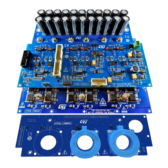
The STEVAL-CTM009V1 evaluation kit for motor control is designed to demonstrate the capabilities of ST Power MOSFETs
based on STripFET™ F7 technology. The 100V STripFET™ F7 devices (STH31*N10F7) are ideal for low voltage (up to 48 V),
high current applications such as forklifts, golf carts and power tool.
The STEVAL-CTM004V1 power board features an insulated metal substrate (IMS), NTCs for thermal protection and decoupling
gate resistors for each power MOSFET. The board mounts ST devices in the H²PAK-6 package.
The driver stage is an STEVAL-CTM006V1 board with L6491 high current capability gate drivers to drive the power MOSFETs
and integrated comparator for protections. The driver board includes the ST motor control connector, so you can interface the
STEVAL-CTM009V1 with any ST MCU control board suitable for motor control (not included in the kit).
The system also has an STEVAL-CTM005V1 bus link capacitor board and an STEVAL-CTM008V1 current sensing board.
Figure 1.
STEVAL-CTM009V1 evaluation kit
UM2458 - Rev 1 - October 2018
www.st.com
For further information contact your local STMicroelectronics sales office.
Advertisement
Table of Contents

Summary of Contents for STMicroelectronics STEVAL-CTM004V1
- Page 1 The STEVAL-CTM004V1 power board features an insulated metal substrate (IMS), NTCs for thermal protection and decoupling gate resistors for each power MOSFET. The board mounts ST devices in the H²PAK-6 package.
-
Page 2: Evaluation Kit Features
UM2458 Evaluation kit features Electrical and functional characteristics The kit features the following main characteristics: • Power board with insulated metal substrate (IMS) hosting 36 STH310N10F7 or STH315N10F7 power MOSFETS in the H²PAK-6 (6x switch) package, designed also for automotive applications. •... -
Page 3: Safety And Operating Instructions
UM2458 Safety and operating instructions General terms All operations involving transportation, installation and use, as well as maintenance, has to be carried out by skilled technical personnel (national accident prevention rules must be observed). For the purpose of these basic safety instructions, "skilled technical personnel"... -
Page 4: Evaluation Kit Overview
UM2458 Evaluation kit overview Evaluation kit overview The STEVAL-CTM009V1 evaluation kit is designed to let you evaluate STH31*N10F7 power MOSFETs, which are driven by high and low-side, L6491 high current capability gate drivers. The system includes a bulk capacitor board and a current sensing board. The STEVAL-CTM009V1 can be interfaced with any ST MCU evaluation board with embedded ST motor control and ST FOC firmware library support. -
Page 5: Steval-Ctm004V1 Power Board
STEVAL-CTM004V1 power board STEVAL-CTM004V1 power board The STEVAL-CTM004V1 power board of the evaluation kit has 36 STH31*N10F7 N-channel Power MOSFETS in the H²PAK-6 package. A gate resistor is placed near each power MOSFET to eliminate parasitic oscillation. A pull-down resistor between the gate and the source of each transistor helps to avoid capacitive coupling driving the transistor and unwanted switch-on when gate is floating. -
Page 6: Sth315N10F7 N-Channel Power Mosfet Characteristics
UM2458 STH315N10F7 N-channel Power MOSFET characteristics • Among the lowest R on the market DS(on) • Excellent figure of merit (FoM) • Low C ratio for EMI immunity • High avalanche ruggedness Figure 4. Package and internal schematic diagram UM2458 - Rev 1 page 6/40... -
Page 7: Driver Board And Control Board Overview
UM2458 Driver board and control board overview Driver board and control board overview Figure 5. STEVAL-CTM006V1 driver board functional blocks 1. connections to power board 2. motor control connector 3. ENC/HALL connector 4. ICS connector 5. L6491 drivers 6 3V3 DC/DC regulation 7. -
Page 8: L6491 Gate Driver Characteristics
UM2458 Table 2. NTC electrical characteristics Symbol Parameter Test Condition Unit Resistance T = -40°C 105.7 kΩ Resistance T = 25°C kΩ Resistance T = 100°C 0.426 kΩ B- constant T = 25°C to 50°C 3500 Operating temp range °C 5.1.4 L6491 gate driver characteristics The L6491 gate driver has the following main features:... - Page 9 UM2458 Pin number Pin name Type Function Lower section supply voltage Deadtime setting SGND Signal ground PGND Power ground Low-side driver output Comparator negative input Comparator positive input Not connected High-side (floating) common voltage High-side driver output BOOT Bootstrapped supply voltage UM2458 - Rev 1 page 9/40...
-
Page 10: Steval-Ctm005V1 Bus Link Capacitor Board
UM2458 STEVAL-CTM005V1 bus link capacitor board STEVAL-CTM005V1 bus link capacitor board In EV inverter systems, bus link capacitors reduce ripple current and suppress voltage spikes caused by leakage inductance and switching operations. These capacitors provide a low impedance path for the ripple currents caused by output inductance load, the bus voltage and PWM frequency. -
Page 11: Steval-Ctm008V1 Current Sensing Board
UM2458 STEVAL-CTM008V1 current sensing board Figure 8. STEVAL-CTM008V1 current sensing board UM2458 - Rev 1 page 11/40... -
Page 12: How To Set Up The System
Step 2. Connect the STEVAL-CTM004V1 power board with the STEVAL-CTM006V1 driver board. – use connectors CON5, CON6, CON7 and J3 on the STEVAL-CTM004V1 power board – use connectors CON1, CON3, CON4 and J2 on the STEVAL-CTM006V1 driver board Step 3. -
Page 13: Figure 9. Current Sensing Connector (Con2 On Driver Board)
UM2458 Connectors Figure 9. Current sensing connector (CON2 on driver board) Table 4. Current sensing connector pinout Pin number Pin name / Function Ground ADC_U Ground ADC_V Ground ADC_W Ground Not Connected Ground Vcc_ICS Figure 10. 34-pin motor control connector (J1 on the driver board) Table 5. -
Page 14: Signal Leds
Enc Z/H3 Signal LEDs Table 6. LEDs Indicators on board Name Color Description Location STEVAL-CTM006V1 STEVAL-CTM006V1 STEVAL-CTM006V1 STEVAL-CTM004V1 Push buttons Table 7. Push buttons Name Description Location STM32 microcontroller reset Control Board User push-button Control Board UM2458 - Rev 1... -
Page 15: Firmware For Stm32 Pmsm Foc Sdk
UM2458 Firmware for STM32 PMSM FOC SDK Firmware for STM32 PMSM FOC SDK This evaluation kit is compatible with latest X-CUBE-MCSDK - STM32 FOC firmware library, please visit the CUBE-MCSDK web page on www.st.com for information and installation instructions. Firmware for STM32 PMSM FOC SDK You can use the ST Motor control workbench to customize the STM32 FOC library (installed together with the CUBE-MCSDK package). -
Page 16: Firmware For Stm32 Pmsm Foc Sdk
UM2458 Firmware for STM32 PMSM FOC SDK Parameter Value Unit U,V,W driver enabled Force same values for U, V, W driver U,V,W driver disabled Use STGAP1S gap drive UM2458 - Rev 1 page 16/40... -
Page 17: Experimental Measurements
UM2458 Experimental measurements Experimental measurements The experimental results were obtained by testing the system at maximum power rating. The power board was mounted with a heatsink (manuf.: ABL Components; manuf. order code: 159AB2000B; Rth: 0.36 °C/W; dimensions: 200x160x40mm, or equivalent), using a thermal interface material with high thermal conductivity (1300 W/mK) to form a natural convection cooling system. -
Page 18: Figure 12. Measured Temperatures Of U_Phase Power Mosfets
UM2458 Experimental measurements Figure 12. Measured temperatures of U_phase Power MOSFETs The following table shows the MOSFET maximum, minimum and average temperature values. Table 8. Measured case temperatures of the STH315N10F7 power MOSFETs High Side Uphase devices Low Side Uphase devices Case Temperature [°C] max. -
Page 19: Steval-Ctm0091V1 Kit Schematic Diagrams
UM2458 STEVAL-CTM0091V1 kit schematic diagrams 10.1 STEVAL-CTM004V1 schematic diagram Figure 13. STEVAL-CTM004V1 power board schematic BUS+ GATE GATE Source Source NTC+ NTC+ NTC- NTC- GATE GATE Source Source GATE GATE GATE GATE GATE GATE 0.033uF 5 6 7 5 6 7... -
Page 20: Steval-Ctm005V1 Schematic Diagram
UM2458 STEVAL-CTM005V1 schematic diagram 10.2 STEVAL-CTM005V1 schematic diagram Figure 14. STEVAL-CTM005V1 capacitor board schematic PADs for High Current - 200A DC_BUS+_U DC_BUS+_V DC_BUS+_W TW10 TW11 DC_BUS+ DC_BUS- LS_Source_U_D DC_BUS-_U DC_BUS-_V DC_BUS-_W 10.3 STEVAL-CTM006V1 schematic diagrams HS_Gate_U_D HS_Gate_V_D HS_Gate_W_D LS_Source_U_D LS_Source_V_D LS_Source_W_D NTC+_U LS_Source_V_D NTC+_W... -
Page 21: Steval-Ctm006V1 Schematic Diagrams
UM2458 STEVAL-CTM006V1 schematic diagrams Figure 16. STEVAL-CTM006V1 driver board schematic - sensing +5V_D +3V3_D +3V3_D +5V_D +12V_D +3V3_M NTC+ 1.33k 3.57k +5V_D Temp.Monitoring 135 °C= 3.3V NTC- Iph_U +3V3_M Iph_U Iph_V Iph_V Iph_W Iph_W 1.5k +5V_D CH1_N 0.1uF Vcc_ICS CH1_N CH2_N POWER_GND GND_D... -
Page 22: Figure 17. Steval-Ctm006V1 Driver Board Schematic - Gate Drivers
UM2458 STEVAL-CTM006V1 schematic diagrams Figure 17. STEVAL-CTM006V1 driver board schematic - gate drivers U PHASE GND_D GND_D GND_P GND_P TP27 +3V3_D Expected 2.58V at 220Apk with LEM HTFS 200-P 5000 +3V3_D I_sense +12V_D +12V_D R243 +3V3_D R244 R245 Gate_HS R246 C631 µF STTH102AY 4.7k... -
Page 23: Figure 18. Steval-Ctm006V1 Driver Board Schematic - Overcurrent Protection
UM2458 STEVAL-CTM006V1 schematic diagrams Figure 18. STEVAL-CTM006V1 driver board schematic - overcurrent protection 3V3_D 3V3_D R251 0.1µF GND_D SD_1 SD_2 MM74HC08MTCX GND_D FAULT 0.1µF 0.1µF MM74HC08MTCX GND_D GND_D GND_D SD_3 MM74HC08MTCX 0.1µF GND_D 0.1µF GND_D GND_D GND_D MM74HC08MTCX GND_D GND_D Figure 19. -
Page 24: Steval-Ctm008V1 Schematic Diagram
UM2458 STEVAL-CTM008V1 schematic diagram 10.4 STEVAL-CTM008V1 schematic diagram Figure 20. STEVAL-CTM008V1 current sensing board schematic Vref ICS1 +Vref IPH_U Iph_U Vref 3.6K 1.8K HTFS 200-P 1 +5V ICS2 CON10A IPH_V Iph_V 4 Vref 3.6K 1.8K IPH_U IPH_V HTFS 200-P IPH_W IBAT male Vref... -
Page 25: Steval-Ctm009V1 Kit Bill Of Materials
STEVAL- Current sensing not available CTM008V1 board separately 11.1 STEVAL-CTM004V1 bill of materials Table 10. STEVAL-CTM004V1 power board bill of materials Item Q.ty Ref. Part / Value Description Manufacturer Order code 0.033uF 1206 C80, C83, C85, CAP CER 0.033UF... -
Page 26: Steval-Ctm004V1 Bill Of Materials
UM2458 STEVAL-CTM004V1 bill of materials Item Q.ty Ref. Part / Value Description Manufacturer Order code R71, R72, R73, R74, R75, R76, R84, R85, R87, R88, R89, R90, R107, R108, R109, R110, R111, R112, R120, R121, 2.2 1206 (3216 R122, R123,... -
Page 27: Steval-Ctm005V1 Bill Of Materials
UM2458 STEVAL-CTM005V1 bill of materials 11.2 STEVAL-CTM005V1 bill of materials Table 11. STEVAL-CTM005V1 capacitor board bill of materials Item Q.ty Ref. Part / Value Description Manufacturer Order code C6, C7, C8, C9, C10, C11, C12, C13, C14, C15, 270µF Radial, C16, C17, C18, CAP ALUM Rubycon... - Page 28 UM2458 STEVAL-CTM006V1 bill of materials Item Q.ty Ref. Part / Value Description Manufacturer Order code C2012X5R1H335K125 C101, C106 3.3µF 50V ±10% CAP CER X5R 0805 Corporation 150pF 100V CGA3E2C0G2A151J0 C102 CAP CER C0G 0603 ±5% Corporation 80AD CGA3E2C0G1H121J0 C107 120pF 50V ±5% CAP CER C0G 0603 Corporation 80AD...
- Page 29 UM2458 STEVAL-CTM006V1 bill of materials Item Q.ty Ref. Part / Value Description Manufacturer Order code Sullins SFH11-PBPC-D07-ST- Multipole Male Connector Connector Solution 2-position vert Phoenix TERM BLOCK HDR 1803426 3.81mm Contact Wurth 120Ω @ FERRITE BEAD L1, L2, L3, L4 Electronics 742792625 100MHz...
- Page 30 UM2458 STEVAL-CTM006V1 bill of materials Item Q.ty Ref. Part / Value Description Manufacturer Order code R159 1kΩ 1/10W ±1% RES SMD 0603 Yageo RC0603FR-071KL 110kΩ 1/10W R160 RES SMD 0603 Yageo RC0603JR-07110KL ±5% 47kΩ 1/10W R161 RES SMD 0603 Yageo RC0603FR-0747KL ±1% 220Ω...
-
Page 31: Steval-Ctm008V1 Bill Of Materials
UM2458 STEVAL-CTM008V1 bill of materials Item Q.ty Ref. Part / Value Description Manufacturer Order code SIL VERTICAL PC Con3 Harwin Inc. M20-9990345 TAIL PIN HEADER TP15, TP19, TEST POINT PC Keystone TP21, TP25, 5000 5000 MINI .040"D RED Electronics TP27, TP31 TP16, TP17, TP18, TP20, TP22, TP23,... - Page 32 UM2458 STEVAL-CTM008V1 bill of materials Item Q.ty Ref. Part / Value Description Manufacturer Order code 10 Position Cable Assembly Flat cable 150mm Harwin Inc. M50-9100542 Rectangular Socket to Socket 2X2,54 mm + S1,S2,S3,S4 Jumper, Strip line male siptm2002 UM2458 - Rev 1 page 32/40...
-
Page 33: Pcb Layouts
UM2458 PCB layouts PCB layouts The STEVAL-CTM004V1 power board is built on an IMS mono layer with a copper thickness of 175 µm. The board is designed for optimal thermal management under high current conditions. Figure 21. STEVAL-CTM004V1 power board layout The STEVAL-CTM006V1 driver board is a 2-layer PCB, thickness 1.6 mm and copper thickness 70 µm. -
Page 34: Figure 22. Steval-Ctm006V1 Driver Board Layout
UM2458 PCB layouts Figure 22. STEVAL-CTM006V1 driver board layout UM2458 - Rev 1 page 34/40... -
Page 35: Revision History
UM2458 Revision history Table 14. Document revision history Date Version Changes 04-Oct-2018 Initial release. UM2458 - Rev 1 page 35/40... -
Page 36: Table Of Contents
STEVAL-CTM004V1 schematic diagram ........ - Page 37 STEVAL-CTM004V1 bill of materials ........
- Page 38 Main blocks of the STEVAL-CTM004V1 power board ........
- Page 39 STEVAL-CTM004V1 power board bill of materials ........
- Page 40 IMPORTANT NOTICE – PLEASE READ CAREFULLY STMicroelectronics NV and its subsidiaries (“ST”) reserve the right to make changes, corrections, enhancements, modifications, and improvements to ST products and/or to this document at any time without notice. Purchasers should obtain the latest relevant information on ST products before placing orders. ST products are sold pursuant to ST’s terms and conditions of sale in place at the time of order acknowledgement.
Need help?
Do you have a question about the STEVAL-CTM004V1 and is the answer not in the manual?
Questions and answers