
Summary of Contents for Giddings & Lewis MMC-A2
- Page 1 Hardware Manual Part Number M.1300.7165 Version 12.0 Giddings & Lewis Controls, Measurement and Sensing...
- Page 2 NOTE Progress is an on-going commitment at Giddings & Lewis. We continually strive to offer the most advanced products in the industry; therefore, information in this document is subject to change without notice. The illustrations and specifications are not binding in detail. Giddings & Lewis shall not be liable for any technical or editorial omissions occurring in this document, nor for any consequential or incidental damages resulting from the use of this document.
-
Page 3: Table Of Contents
Table of Contents: MMC Hardware Manual 1 Safety Precautions ..................... 1.1 System Safety .................... 1.1.1 User Responsibility................1.1.2 Safety Instructions ................1.2 Safety Signs ....................1.3 Warning Labels ..................1.4 Safety First ....................1.5 Safety Inspection ..................1.5.1 Before Starting Operations ............... 1.6 After Shutdown .................. - Page 4 8.3.1.1 Power LED ................ 8.3.1.2 Scan LED ................8.3.1.3 Diagnostic LEDs ..............8.3.2 Run-Time Diagnostics ..............9 MMC Connections to External Devices for Machine Control ..... 9.1 PiCPro Port ....................9.2 Block I/O Port .................... 9.3 User Port ....................9.4 General I/O Port ..................9.5 Power Connection ..................
- Page 5 B.1 - MMC DeviceNet Module ................. B.1-1 Introduction ....................B.1-1 Connections ....................B.1-2 The DeviceNet Port ................B.1-3 The Configuration (RS232) Port ............B.1-3 LEDs ......................B.1-4 Theory of Operation ................... B.1-5 Specifications ..................... B.1-6 C.1 - Breakout Boxes, Centurion Connector Cables and Flying Lead Cables C.1-1 Breakout Boxes and Cables ...............
- Page 6 E.1 - CE and EMC Guidelines ................. E.1-1 Background on EMC (Electromagnetic Compatibility) Compliance ..E.1-1 Background on Low Voltage Compliance ..........E.1-1 RFI Emission and Immunity ..............E.1-2 Classes of EMC Operating Environments ..........E.1-3 Conformance with the EMC Directive ............E.1-4 Conformance With the Low Voltage Directive .........
-
Page 7: Safety Precautions
Safety Precautions Safety Precautions READ AND UNDERSTAND THIS SECTION IN ITS ENTIRETY BEFORE UNDERTAKING INSTALLATION OR ADJUSTMENT OF MMC CONTROL EQUIPMENT The advice contained in this section will help users to operate and maintain the equipment in a safe manner at all times. PLEASE REMEMBER THAT SAFETY IS EVERYONE'S RESPONSIBILITY System Safety The basic rules of safety set forth in this section are intended as a guide for... -
Page 8: Safety Signs
Safety Precautions ATTENTION - DANGER TO LIFE Do not touch the main power supply fuses or any components internal to the power modules while the main power supply switch is ON. Note that when the main power switch is OFF, the incoming supply cable may be live. -
Page 9: Warning Labels
Safety Precautions Warning Labels Hazard warning Danger Electric Shock Risk When you see this safety sign on a system, it gives a warning of a hazard or possibility of a hazard existing. The type of warning is given by the pictorial representation on the sign plus text if used. -
Page 10: Safety First
Safety Precautions Safety First Giddings & Lewis equipment is designed and manufactured with consideration and care to generally accepted safety standards. However, the proper and safe performance of the equipment depends upon the use of sound and prudent operating, maintenance and servicing procedures by trained personnel under adequate supervision. -
Page 11: Electrical Service & Maintenance Safety
Safety Precautions Where access to the control system is permitted for manual operation, only those doors which provide that access should be unlocked. They should be locked immediately after the particular operation is com- pleted. Never remove warnings that are displayed on the equipment. Torn or worn labels should be replaced. -
Page 12: Safe Cleaning Practices
Safety Precautions There may be circumstances where troubleshooting on live equipment is required. Under such conditions, special precautions must be taken: Make sure your tools and body are clear of the areas of equipment • which may be live. Extra safety measures should be taken in damp areas. •... -
Page 13: Introduction
VDC) and 16 outputs (24 VDC)] can be expanded using Giddings & Lewis serially distributed block I/O. There are also eight (four) low current DC and four (two) DC inputs on the Axis connectors of the MMC-A4 and MMC-A2. Field-installable options for the MMC include an Ethernet TCP/IP interface and a DeviceNet™... - Page 14 Analog Motion SERCOS Motion Control Side Control Side Machine Control Machine Control Side Side (Common to all (Common to all MMC Controls) MMC Controls) MMC-A4 (or MMC-A2) Servo Control MMC SERCOS Control (One-Ring Port) MMC Hardware Manual GIDDINGS & LEWIS...
-
Page 15: Machine Control Board
Introduction 2.2.1 Machine Control Board A Machine Control Board and it’s related external connections are located on the right side of the control. The Machine Control Board contains the CPU. Ladder logic programming is used for machine control. This board also provides the PiCPro serial interface port, block I/O interface port, user serial interface port and a general I/O port consisting of 16 DC outputs and 16 DC inputs Available I/O... -
Page 16: Sercos Board
Introduction Available I/O 2 1/2 Axis 4 1/2 Axis Analog Inputs Analog Outputs Encoder Inputs Axis DC Inputs Axis DC Outputs Axis Fast DC Inputs AUX I/O Port DC Inputs 2.2.2.2 SERCOS board The SERCOS Motion Control board provides a fiber optic input and output for one SERCOS ring. -
Page 17: Option Modules
Introduction 2.2.3 Option Modules Optional communications modules provide special functions such as an Ethernet or DeviceNet interface. Figure 2 depicts an option module connected to an MMC Control. Figure 2: Option Module Connected to MMC Control M M C O p tio n M od u le M o d u le GIDDINGS &... - Page 18 Introduction NOTES MMC Hardware Manual GIDDINGS & LEWIS...
-
Page 19: Mounting The Mmc Control
Mounting the MMC Control Mounting the MMC Control Mount the unit to your cabinet using the mounting slots on the MMC. The MMC unit may be mounted vertically or horizontally. The recommended size of mounting hardware is #10 bolts with #10 star washers (to ensure proper ground connection) as shown in Figure 3 Figure 3: MMC Mounting Dimensions 1.06"... - Page 20 Mounting the MMC Control NOTES MMC Hardware Manual GIDDINGS & LEWIS...
-
Page 21: Adding An Option Module To The Mmc Control
Adding an Option Module to the MMC Control Adding an Option Module to the MMC Control Option modules are shipped with a 50-pin square post connector and screws needed to attach the module to the MMC. Follow the procedure below to add an option module to the MMC. - Page 22 Adding an Option Module to the MMC Control Lift the side cover off and set aside. Locate the 50-pin square post socket at the top of the MMC board. Press one side of the 50-pin square post male connector into this socket ensuring that the pins are aligned and it is firmly seated.
-
Page 23: Dimensions And Mounting Of Mmc With Option Module Attached
Dimensions and Mounting of MMC with Option Module Attached Dimensions and Mounting of MMC with Option Module Attached After attaching the option module to the MMC module, mount the unit to your cabinet using the mounting slots on the MMC and the option module. The recommended size of mounting hardware is #10 bolts with #10 star washers (to ensure proper ground connection). - Page 24 Dimensions and Mounting of MMC with Option Module Attached NOTES MMC Hardware Manual GIDDINGS & LEWIS...
-
Page 25: System Power And Environment Requirements
System Power and Environment Requirements System Power and Environment Requirements General Power and Environment Requirements The MMC is suitable for operation in a pollution degree 2 environment (i.e., normally, only non-conductive pollution occurs). You are not required to install the system rack in a control cabinet. However a cabinet protects the system from dust and mechanical damage and is recommended. -
Page 26: Power Distribution Diagram
System Power and Environment Requirements Power Distribution Diagram The MMC requires an external DC power source. The power distribution drawing that follows shows an MMC connected to a µDSM Drive. The drive’s 24 VDC power is supplied via the MMC in this example. If the drive has its own external 24 VDC supply, the +24 V line would not be connected. -
Page 27: Notes For 24V Power Supply And Mmc
System Power and Environment Requirements It is recommended that the same main disconnect switch be used for the MMC system and for all devices in the application. IMPORTANT No matter how the system is installed, before you connect the MMC to the application, make sure that power is off to the system and to the devices the MMC is wired to. - Page 28 MMC Module Subtotal Current (mA) Units (mA) (mA) MMC-A2 or MMC-A4 MMC SERCOS MMC Ethernet MMC DeviceNet Subtotal, Power Bus 1 (Add Column A, Lines 1 or 2 and 3 or 4 (3000 mA max) Actual Col A Col B...
- Page 29 MMC Module Subtotal Current (mA) Units (mA) (mA) MMC-A2 or MMC-A4 MMC SERCOS MMC Ethernet MMC DeviceNet Subtotal, Power Bus 1 (Add Column A, Lines 1 or 2 and 3 or 4 (3000 mA max) Actual Col A Col B...
-
Page 30: Grounding The System
System Power and Environment Requirements Grounding the System The ground of the MMC power source must be connected directly to a Single Point Ground (SPG) tie block. The tie block should be made of brass or copper, bolted or brazed to the control cabinet. If the tie block is bolted rather than brazed, scrape away paint or grease at the point of contact. -
Page 31: Controlling Heat Within The System
System Power and Environment Requirements IMPORTANT You must ensure that the "0V" or "Common" of all devices connected to the MMC are connected to Single Point Ground (SPG). Failure to do so may result in erratic operation or damage to the MMC. Exam- ples of devices connected to the MMC include the power source that supplies 24VDC power to the MMC and devices connected to the MMC PiCPro Port or User Port. -
Page 32: Handling An Mmc
System Power and Environment Requirements The MMC itself is a source of heat, though in most installations its heat dissipates without harmful effects. System heat is generated from power dissipated by: field side input/output components • other components within the MMC •... -
Page 33: System Wiring Guidelines
System Wiring Guidelines System Wiring Guidelines The MMC relies on electrical signals to report what is going on in the application and to send commands to it. In addition, signals are constantly being exchanged within the system. The MMC is designed for use in industrial environments, but some guidelines should be followed. - Page 34 System Wiring Guidelines Inside a control cabinet, connect the shields of shielded cables at the MMC. Figure 8 illustrates shielded cable entering/leaving the cabinet. Figure 8: Connecting Shielded Cable External Drive Cabinet Enclosure The two different methods of terminating shields are used to accommodate two different immunity requirements.
-
Page 35: Differential Devices For Analog And Encoder Signals
System Wiring Guidelines Differential Devices for Analog and Encoder Signals A differential device receives or sends one signal over two wires (typically a shielded twisted pair). The input/output voltage at the second terminal is the inverse of the first. Information is received/sent as the difference between the two voltages. - Page 36 System Wiring Guidelines NOTES MMC Hardware Manual GIDDINGS & LEWIS...
-
Page 37: Starting An Operation
Starting an Operation Starting an Operation Good procedure suggests that the system should be tested each time a new application is powered up. The DIAG LED on the MMC should be off indicating that the diagnostic tests were passed. Turn off the main disconnect switch and plug the DC connector into the power connector. -
Page 38: Troubleshooting
Starting an Operation Troubleshooting Table 2 summarizes how to proceed when performing certain maintenance and/or setup functions. Table 2: Summary In order to: Turn off the entire application. Turn off main disconnect (which should also turn off all external power supplies to the application);... -
Page 39: Diagnostics
Starting an Operation Diagnostics This section covers two types of diagnostics; power-on and run-time. 8.3.1 Power-On Diagnostics When the system is powered up, it tests itself and reports the results of the tests in the form of LED signals. 8.3.1.1 Power LED If the power light (P) does not go on, or goes off during operation of the system, check that power is still... -
Page 40: Run-Time Diagnostics
Starting an Operation NOTE Diagnostics are run only when the system is powered up. It is possi- ble that a failure might occur during operation. If so, its DIAG light remains off. If you suspect that a module might be defective, cycle power to run diagnostics again. -
Page 41: Mmc Connections To External Devices For Machine Control
MMC Connections to External Devices for Machine Control MMC Connections to External Devices for Machine Control Giddings & Lewis provides many optional accessories that simplify wiring the MMC to external devices. These accessories include cables to connect the MMC to Giddings &... -
Page 42: Block I/O Port
MMC Connections to External Devices for Machine Control Block I/O Port The block I/O port provides up to 77 expansion block I/O units, 4-wire communication interface and up to 200 feet between block I/O units Block I/O Communications Controller Block I/O Type Connector 9-Pin D-Sub Female Connector... -
Page 43: User Port
MMC Connections to External Devices for Machine Control User Port The User Port is used to communicate with a touch-screen, a hand-held controller, or other serial interface device. The user port provides: RS232/RS485 communication • Baud rates to 19.2 K •... -
Page 44: General I/O Port
MMC Connections to External Devices for Machine Control General I/O Port The general I/O port includes: 16 24 VDC inputs • Sink or source in groups of eight Inputs 1 and 9 can trigger an interrupt on the rising or falling edge +24 VDC and 24 V Common •... - Page 45 MMC Connections to External Devices for Machine Control There are 16 DC outputs on the general connector. These outputs get their power internally from the MMC as shown in Figure 10 Figure 10: General Outputs Connected to Loads GENERAL CONNECTOR DC OUTPUT PINS L O A D D C O U T 1...
- Page 46 MMC Connections to External Devices for Machine Control There are 16 general inputs on the general connector. The inputs are configured as two groups of eight. Each group can be configured as sourcing or sinking. Connect the DCSS pin to +24 V for a sourcing configuration. Connect the DCSS pin to COM for a sinking configuration.
-
Page 47: Power Connection
MMC Connections to External Devices for Machine Control Power Connection You must provide a +24 VDC power supply as the power source for the MMC. The power supply screw terminal connection (3 pin) is at the bottom of the CPU section of the MMC. This +24 V appears as an output at several points on the MMC connectors. - Page 48 MMC Connections to External Devices for Machine Control NOTES MMC Hardware Manual GIDDINGS & LEWIS...
-
Page 49: Mmc Analog Servo Connections For Motion Control
MMC Analog Servo Connections for Motion Control 10 MMC Analog Servo Connections for Motion Control There are four Axis connectors and one Auxiliary I/O connector on the MMC analog board. 10.1 Axis Connectors Each axis has its own 15 pin high density D connector. Each axis connector provides the following signal connections: One 16-bit resolution analog output (±10 VDC) •... - Page 50 MMC Analog Servo Connections for Motion Control The metal shell of the 15-pin connector is tied to the chassis ground terminal on the MMC power connector. Cables provided by Giddings & Lewis will have the shield connected to the metal shell of the cable connector. If you use other cables, be sure to connect the shield to the metal shell of the connector.
- Page 51 MMC Analog Servo Connections for Motion Control When the DCOSS pin is tied to COMMON, the outputs will be in a sink configuration as shown in Figure 14. Figure 14: Sink Configuration +24V DC OUT 1 Drive Enable DCOSS +24V DC OUT 2 Drive Reset...
- Page 52 MMC Analog Servo Connections for Motion Control The analog output is connected to the drive command input. Twisted pair wire should be used to make the connection between the analog output and the drive as shown in Figure 15. Figure 15: Axis Analog Output Connected to Drive Command Input MM C Axis Connector Drive D A +...
- Page 53 MMC Analog Servo Connections for Motion Control The encoder output signals from the drive should be connected to the encoder input on each axis. The MMC analog section accepts RS422 level differential inputs. The encoder signals should be quadrature type. All encoder wiring between the MMC and the drive should be shielded twisted pair.
-
Page 54: Auxiliary I/O Connector
MMC Analog Servo Connections for Motion Control 10.2 Auxiliary I/O Connector The auxiliary I/O 44-pin connector provides the following inputs: One quadrature, incremental encoder channel (1 Mhz frequency, • RS422 interface) Five fast DC inputs (one per encoder input) for high speed posi- •... - Page 55 MMC Analog Servo Connections for Motion Control The auxiliary I/O connector pinout for the MMC-A2 (2 axes) is listed below Description Description Description FASTIN1+ DCSSA FASTIN1- DCIN1 SHIELD DCIN2 FASTIN2+ DCIN3 FASTIN2- DCIN4 SHIELD DCIN5 SHIELD DCIN6 +24 VDC out 23...
- Page 56 MMC Analog Servo Connections for Motion Control Each encoder channel has a fast DC input associated with it. The fast input can be used to latch the encoder position. Shielded twisted pair wiring should be used for all fast input connections. The fast inputs can be connected in either a source or sink configuration.
- Page 57 MMC Analog Servo Connections for Motion Control There are 12 general purpose inputs on the auxiliary connector. The inputs are configured as two groups of six. Each group can be configured as sourcing or sinking. Connect the DCSS pin to +24 V for a sourcing configuration.
- Page 58 MMC Analog Servo Connections for Motion Control Figure 21: Sink/Source Connections using External DC Supply(4-Axis MMC) MMC AUX Connector + 2 4 V D C S S A D C IN 1 D C IN 2 D C IN 3 SINKING INPUTS D C IN 4...
-
Page 59: Mmc Sercos Connections For Motion Control
MMC SERCOS Connections for Motion Control 11 MMC SERCOS Connections for Motion Control 11.1 SERCOS Receive and Transmit Ports The SERCOS port located in the center of the board can connect to one SERCOS ring. The connection to this ring is made through a pair of female fiber optic SMA connectors. -
Page 60: Serial (Loader) Port
MMC SERCOS Connections for Motion Control Table 3: SERCOS Fiber Optic Cables Description Length Part Number Standard Cable 1’ M.1016.9743 (old # 502-04170-01) 3’ M.1016.9744 (old # 502-04170-03) 5’ M.1016.9745 (old # 502-04170-05) 10’ M.1016.9747 (old # 502-04170-10) 15’ M.1016.9749 (old # 502-04170-15) 25’... -
Page 61: Basic Mmc Theory Of Operation
Basic MMC Theory of Operation 12 Basic MMC Theory of Operation 12.1 Machine Control Board Operation Figure 24: MMC Machine Control Board External Components MMC SERCOS Control MMC-A4 (or MMC-A2) Servo Control (One-Ring Port) LEDs LEDs PicPro PicPro Port Port... -
Page 62: Leds
Basic MMC Theory of Operation 12.2 LEDs There are three LEDs on the top of the CPU section of the MMC. Figure 25: LEDs Below is a list of the LEDs and what they mean. Scan (S) Green The processor is executing the application program. Scan is lost and there is an orderly shut down procedure followed. -
Page 63: Diagnostic Error Codes
Basic MMC Theory of Operation 12.3 Diagnostic Error Codes While the MMC is running, the DIAG LED on the CPU module will flash a three digit code signal if there is an error. For example, if there is a long pause-flash-pause-flash-flash-pause-flash-flash-flash-long pause, the code is 123. -
Page 64: Mmc Machine Control
Basic MMC Theory of Operation 12.4 MMC Machine Control The MMC converts input power into DC power at voltages of + 5V, + 15 V, and - 15 V and supplies them to the logic side of the system.The same supply that powers the MMC can be used for the fieldside of the system. -
Page 65: General I/O Output Operation
Basic MMC Theory of Operation Even though you have placed an application in flash, you can still download and run a different application from PiCPro. However, when you cycle power on the MMC, the application in flash will always be placed into RAM. 12.6 General I/O Output Operation Each of the 16 outputs on the general I/O connector is a solid state switch rated at .250 A. -
Page 66: Dc Output Theory Of Operation (Axis Connector)
Basic MMC Theory of Operation Figure 26: Diagram of Internal Protection for Inductive Loads DC Pow er Supply DC Pow er Supply M M C PO W ER General O utput G eneral Output M M C PO W ER C ON NECTO R CO NNECTOR Output... -
Page 67: Dc Input Operation (Axis, Aux, General Connectors)
Basic MMC Theory of Operation 12.9 DC Input Operation (Axis, AUX, General Connectors) Each input is guaranteed "on" at 14 to 30 VDC and guaranteed "off" at 0 to 5 VDC; polarity doesn't matter. Its on/off state is converted to a corresponding logic 1 or 0. - Page 68 Basic MMC Theory of Operation IMPORTANT Switching devices can sometimes have a leakage current that ex- ceeds the IT (current allowed when off) of an input module. In or- der to use such a device, an impedance (typically, a resistor) needs to be used in parallel with the input.
-
Page 69: Analog Servo Control Operation
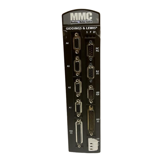
Analog Servo Control Operation 13 Analog Servo Control Operation Figure 28: Locations of Input, Output, Encoder Pins on the MMC-A4 Unit 15-pin Axis Connectors 1 Analog Output 1 Encoder Input 2 DC Outputs 1 DC input 44-Pin AUX Input 12 DC Inputs 5 Fast DC Inputs 1 Encoder Input +24V... -
Page 70: Analog Output Theory Of Operation (Axis Connectors)
Analog Servo Control Operation 13.1 Analog Output Theory of Operation (Axis Connectors) The CPU sends the analog output section a 16-bit digital word for each analog output channel used. Each digital word is converted to a corresponding voltage within the range of ±10 V. The voltage is buffered and brought out to a pair of I/O connections as a differential type voltage output. -
Page 71: Index
Analog Servo Control Operation The maximum input frequency is 250,000 lines per second, which results in 1,000,000 Feedback Units (FUs) per second. Figure 30: Counting Quadrature Pulses The m odule counts positive transitions at both channel A and channel B. One quadrature cycle in this case gives 4 feedback units. -
Page 72: Analog Input Operation (Aux Connector)
Analog Servo Control Operation 13.3 Analog Input Operation (AUX Connector) There is one differential analog input channel on this module. The input range is ±10 VDC. The analog input voltage is sampled every 100 µsec by a 12-bit A/D converter. The most recent conversion result is stored in an on- board register. -
Page 73: Mmc Sercos Control Operation
MMC SERCOS Control Operation 14 MMC SERCOS Control Operation The MMC SERCOS board is an alternate type of motion control used as part of an MMC base unit. It provides an interface between the MMC and a fiber optic ring. A ring can have from one to eight SERCOS slaves. The module contains an on board processor. - Page 74 MMC SERCOS Control Operation NOTES MMC Hardware Manual GIDDINGS & LEWIS...
-
Page 75: Replacing The Mmc Battery
Replacing the MMC Battery 15 Replacing the MMC Battery Follow the procedure below to replace the MMC battery when the "P" LED is flashing. After DC power has been applied to the MMC for at least five minutes, turn off power. - Page 76 Replacing the MMC Battery Figure 32: Battery Location in MMC Battery Clip Not all components shown Use a screwdriver to gently pry up the battery clip. Slide the battery out. Replace it with a 3V coin cell, BR2032 battery, + side up. Screw the cover or optional modules back on.
-
Page 77: Specifications
Specifications 16 Specifications General Characteristic MMC Specifications Number of servo axes available at six update rates* User Model Part Number Speed MMC-A2 M.1017.3772 256K 128K (old # 503-26606-21) MMC-A4 M.1017.3774 256K 128K (old # 503-26606-41) MMC-S8 M.1017.3770 256K 128K (old # 503-26606-00) *Consult Giddings &... - Page 78 Specifications Time-of-day clock Access via PiCPro 10.2 and above or your application program Clock tolerance At 25°C (77°F),±1 second per day Over temperature, voltage and aging variation, +2/-12 seconds per day Operating temperature range 5°C to 55°C (41°F to 131°F) Storage temperature range -40°C to 85°C (-40°F to 185°F) Humidity...
- Page 79 Specifications Analog Output Output channels 2 or 4 Resolution 16 bits Output voltage range ±10 VDC Maximum output current (1K Ω ±10 mA load) Power on output voltage 0 V ±100 mV Scan loss output voltage 0V ±100 mV Accuracy ±0.375% of FSR Drift ±...
- Page 80 Specifications Encoder Input Input channels 3 or 5 Input receiver type 2632 differential RS422 type receiver Encoder signals Differential quadrature Input threshold ±750 mV Input termination 120 ¾ Maximum input voltage Maximum A or B input 250 K Hz (1 M feedback unit count rate) frequency Fast input voltage Nominal 24 VDC, maximum 30 VDC...
- Page 81 Specifications General DC Outputs Number of outputs 16 outputs Input voltage Nominal 24 VDC, 30 VDC maximum Configuration Two groups of eight solid-state switches. Protection of logic circuits Optical isolation between the logic and field side, transient suppression on the 24V external supply Maximum current .25 A per output Voltage range...
- Page 82 Specifications SERCOS SERCOS Interface Interfaces with one ring with from one to eight digital drives SERCOS port SMA female connectors for interfacing to 1000 µ meter plastic fiber optic cable with SMA male connectors. Fiber optic receiver specifications: Peak input power (optical level low) -31.2dBm max Peak input power (optical level high) -20.0 dBm min, 0.0dBm max Fiber optic transmitter specifications:...
-
Page 83: Mmc Ethernet Tcp/Ip Module
A.1 - MMC Ethernet TCP/IP Module A.1 - MMC Ethernet TCP/IP Module 1 Introduction The ETHERNET - TCP/IP module provides the MMC with Ethernet access and Internet connectivity. A 10Base T connection is provided following the IEEE 802.3 specification. The data transfer rate is 10 Mbps. Applications can range from connecting several MMCs, connecting groups of MMCs and PCs, or connecting to a system that includes Internet access. -
Page 84: Connections
A.1 - MMC Ethernet TCP/IP Module 2 Connections The MMCPro cable is used to make a connection between the PC and the MMC. 1. Connect the PC to the RS232 Com 2 Port on the Ethernet - TCP/IP module to download the TCP/IP configuration file. 2. - Page 85 A.1 - MMC Ethernet TCP/IP Module A typical MMCal 10Base T connection is shown below. Figure A.1-3. Ethernet - TCP/IP 10Base T Connections ETH ERN ET D IA G G D LN K E O C O L P RE V O U T CO M 1 O U T...
-
Page 86: The Ethernet Port
A.1 - MMC Ethernet TCP/IP Module 2.1 The Ethernet Port The 10Base-T port uses a RJ-45 style 8-pin connector using 100 ¾ unshielded twisted pair category 3 or 5 cable (IEEE 802.3 section 14.4). The maximum length of the twisted pair cable segment is 100 m (328 ft.). NOTE: The connector is also suitable for shielded cable and will ground the shield to the chassis. -
Page 87: Leds
A.1 - MMC Ethernet TCP/IP Module 3 LEDs There are nine LEDs on the MMC Ethernet - TCP/IP module in addition to the DIAG LED. They are located directly under the DIAG LED as shown below. Figure A.1-4. Ethernet - TCP/IP LEDs (yellow) Diagnostic DIAG... -
Page 88: Theory Of Operation
A.1 - MMC Ethernet TCP/IP Module 5 Theory of operation The MMCEthernet - TCP/IP module contains a 32-bit processor to handle TCP/ IP, PPP (future), and Ethernet protocols. It allows you to use the Ethernet network architecture and the TCP/IP standard set of protocols to communicate and access other modules, computers, or the Internet and its resources. -
Page 89: Specifications Table
A.1 - MMC Ethernet TCP/IP Module 6 Specifications Table Characteristics Ethernet - TCP/IP Module Specifications Function Provides the MMC with Ethernet access and Internet connectivity Part number M.1017.3888 (old # 503-26683-01) RS232 Port 1 Com Port 1 modem (future) RS232 Port 2 Com Port 2 (for firmware and configuration loading) 10Base T RJ-45 8-pin connector... - Page 90 A.1 - MMC Ethernet TCP/IP Module 7 Useful Internet Links http://www.3com.com/technology/tech_net/white_papers/ 500698.html#6 http://www.library.ucg.ie/Connected/Course/index.htm http://www.combsnet.com/cable/Basics/types.html http://www.jdltech.com/solutions/Standards_Terms.cfm http://www.jdltech.com/solutions/LAN_terms.cfm http://www.datatech.com/hot/w96_2.htm http://www.standards.ieee.org/catalog/IEEE802.3.html http://www.3com.com/nsc/glossary/main.htm http://www.alliedtelesyn.com/prd_tran.htm#microtrans http://www.lothlorien.net/collections/computer/ethernet_frames.html http://www.lantronix.com/htmfiles/mrktg/catalog/etntba.htm http://www.warehouse.com/datacomm/ A.1-8 Ethernet TCP/IP Module GIDDINGS & LEWIS...
-
Page 91: Mmc Devicenet Module
B.1 - MMC DeviceNet Module B.1 - MMC DeviceNet Module 1 Introduction The MMC DeviceNet scanner module is an interface between the MMC and a ™ DeviceNet network. The module contains an on-board processor, a DeviceNet compliant interface, and firmware that makes it act as the master to all other nodes on the network. -
Page 92: Connections
B.1 - MMC DeviceNet Module 2 Connections DeviceNet connections are illustrated in Figure B1-2. Up to 63 DeviceNet Nodes may be attached to the DeviceNet scanner module. Figure B1-2. DeviceNet Connections MMC DeviceNet D e vice N e t DIAG CN FG PO RT NETWORK SCANNER... -
Page 93: The Devicenet Port
B.1 - MMC DeviceNet Module 2.1 The DeviceNet Port The DeviceNet port is on the front of the module near the center as shown in Figure B1-1. The pinout for the DeviceNet port is shown below: Pin # Signal Name Standard Wire Colors black CAN_L... -
Page 94: Leds
B.1 - MMC DeviceNet Module 3 LEDs The two configuration port LEDs and the two DeviceNet port LEDs are described below. Color State Definition Network status None Off-line DeviceNet Port Green On-line and connected to at least one node Flashing On-line but connection nodes not established Unrecoverable Fault (dupli-... -
Page 95: Theory Of Operation
B.1 - MMC DeviceNet Module 4 Theory of Operation The DeviceNet scanner module provides a memory image of the nodes (slaves) connected to a DeviceNet network. It is this memory image that is controlled by your LDO created in PiCPro. The module’s on-board processor continually transfers data between this memory image and the actual DeviceNet nodes. -
Page 96: Specifications
B.1 - MMC DeviceNet Module 5 Specifications Characteristics DeviceNet Module Specifications Function Interfaces to a DeviceNet network with up to 63 other nodes Part number M.1017.3889 (old # 503-26684-00) DeviceNet Port Phoenix style 5-pin male connector Configuration Port RS232 interface 24 V DC Power from the MMC 100 mA Operating temperature range... -
Page 97: Breakout Boxes, Centurion Connector Cables And Flying Lead Cables
C.1 - Breakout Boxes, Centurion Connector Cables and Flying Lead Cables C.1 - Breakout Boxes, Centurion Connector Cables and Flying Lead Cables There are various plug and play connection products available for field wiring of the MMC control. These include Breakout Boxes with appropriate cable, Centurion MicroDSM drive J1 Cables, Centurion DSM drive J1 Cables and Flying Lead Cables. - Page 98 C.1 - Breakout Boxes, Centurion Connector Cables and Flying Lead Cables Figure C1-2: Connection Selector Sheet for MMC SERCOS Control C hoose 1 To Flying Leads M MC Block I/O to Flying Lead To Breakout Box MMC Block I/O to Breakoutbox Cable MMC Block I/O Breakout Box...
-
Page 99: Breakout Boxes And Cables
C.1 - Breakout Boxes, Centurion Connector Cables and Flying Lead Cables 1 Breakout Boxes and Cables There are five basic and one encoder isolator type MMC Breakout Boxes available that simplify wire termination to the MMC Controls. They include the Axis Connector Breakout Box, Auxiliary I/O Connector Breakout Box, Auxiliary I/O Connector Breakout Box with Encoder Isolators, the User Port Connector Breakout Box, the General I/O Connector Breakout Box and the Block I/O... - Page 100 C.1 - Breakout Boxes, Centurion Connector Cables and Flying Lead Cables 1.1.1 Breakout Box for Axis Connector The Breakout Box for the Axis Connector can be attached to A1, A2 A3 and A4 (one per axis) of the on the MMC. The pinouts on the terminal strip interface provide a one-to-one transfer of the signals from the connector to the respective pin(s) on the terminal block.
- Page 101 C.1 - Breakout Boxes, Centurion Connector Cables and Flying Lead Cables 1.1.2 Cable - Breakout Box to MMC Axis Connector Figure C1-4: Cable for Axis Connector to Breakout Box Wiring Diagram 15 Pin HD D-sub 15 Pin HD D-sub Shell Drain Wire Shell To Breakout Box...
-
Page 102: Breakout Box And Cables For Auxiliary I/O Connector
C.1 - Breakout Boxes, Centurion Connector Cables and Flying Lead Cables 1.2 Breakout Box and Cables for Auxiliary I/O Connector Table C1-4: Part No. - Breakout Box and Cables to MMC AUX I/O Connector Description Length Part Number MMC Aux I/O Breakout Box M.1016.2531 (old # 401-57279-00) MMC Connector Breakout Box with... - Page 103 C.1 - Breakout Boxes, Centurion Connector Cables and Flying Lead Cables Figure C1-5: Breakout Box - Auxiliary I/O Connector 1.875” 3.940” 2.625” 5.312” Table C1-5: Pinout - Breakout Box for Auxiliary I/O Connector MMC-A4 (4 axis) Description Description Description FASTIN1+ DCSSA FASTIN1- DCIN1...
- Page 104 C.1 - Breakout Boxes, Centurion Connector Cables and Flying Lead Cables Table C1-6: Pinout - Breakout Box for Auxiliary I/O Connector MMC-A2 (2 axis) Description Description Description FASTIN1+ DCSSA FASTIN1- DCIN1 SHIELD DCIN2 FASTIN2+ DCIN3 FASTIN2- DCIN4 SHIELD DCIN5 SHIELD...
-
Page 105: Auxiliary I/O Connector Breakout Box With Encoder Isolators
C.1 - Breakout Boxes, Centurion Connector Cables and Flying Lead Cables 1.2.2 Auxiliary I/O Connector Breakout Box with Encoder Isolators A second type of auxiliary I/O breakout box has encoder isolator circuits incorporated into the module. These circuits boost the encoder common mode voltages allowed from approximately 10 volts to hundreds of volts. - Page 106 C.1 - Breakout Boxes, Centurion Connector Cables and Flying Lead Cables 1.2.2.1 Encoder Isolator Connections Figure C1-7: Connections from Encoder to Encoder Isolated AUX I/O O ptical Isolator O ptical Isolator N ote: Pin 12, the + 5V (+ 20% ), is not carried thru to the screw term inal.
- Page 107 C.1 - Breakout Boxes, Centurion Connector Cables and Flying Lead Cables 1.2.2.2 Input Requirements for Encoder Isolator Breakouot Box Although the isolator interface can be used single ended or differential, a RS-422 differential type driver is recommended. Table C1-7: Encoder Isolator Breakout Box Input Requirements Input Item Specification Input current/volage (minimum)
-
Page 108: Cable - Breakout Box To Aux I/O Connector
C.1 - Breakout Boxes, Centurion Connector Cables and Flying Lead Cables 1.2.3 Cable - Breakout Box to AUX I/O Connector Figure C1-9: Cable for AUX I/O Connector to Breakout Box 44 Pin HD D-sub 44 Pin HD D -sub Wiring Diagram IMPORTANT: Do not use cables over three feet in... - Page 109 C.1 - Breakout Boxes, Centurion Connector Cables and Flying Lead Cables Table C1-8: : Pinout - Cable for AUX I/O Connector to Breakout Box (MMC-A4) Description Description Description FASTIN1+ DCSSA FASTIN1- DCIN1 SHIELD DCIN2 FASTIN2+ DCIN3 FASTIN2- DCIN4 SHIELD DCIN5 SHIELD FASTIN3+ DCIN6...
- Page 110 C.1 - Breakout Boxes, Centurion Connector Cables and Flying Lead Cables Table C1-9: : Pinout - Cable for AUX I/O Connector to Breakout Box (MMC-A2) Description Description Description FASTIN1+ DCSSA FASTIN1- DCIN1 SHIELD DCIN2 FASTIN2+ DCIN3 FASTIN2- DCIN4 SHIELD DCIN5...
-
Page 111: Breakout Box And Cables For Block I/O Connector
C.1 - Breakout Boxes, Centurion Connector Cables and Flying Lead Cables 1.3 Breakout Box and Cables for Block I/O Connector 1.3.1 Block I/O Connector Breakout Box The Block I/O connector is used for communicating with distributed block I/O modules. Up to 77 blocks can be connected to a single MMC. - Page 112 C.1 - Breakout Boxes, Centurion Connector Cables and Flying Lead Cables Figure C1-10: Breakout Box - BLK I/O Connector 1.750” 3.000” 1.750” 2.250” Table C1-11: Pinout - Breakout Box for Block I/O Connector Desc. In/Out Pin Desc. In/Out Desc. Block I/O Shield Transmit (see Note...
-
Page 113: Cable - Breakout Box To Block I/O Connector
C.1 - Breakout Boxes, Centurion Connector Cables and Flying Lead Cables 1.3.2 Cable - Breakout Box to Block I/O Connector Figure C1-11: Cable for Block I/O Connector to Breakout Box 9 Pin D-sub 9 Pin D-sub W iring Diagram Drain Shell Shell To Breakout Box... -
Page 114: Breakout Box And Cables For User Port Connector
C.1 - Breakout Boxes, Centurion Connector Cables and Flying Lead Cables 1.4 Breakout Box and Cables for User Port Connector 1.4.1 User Port Connector Breakout Box The User Port connector on the MMC control is a serial port typically used for operator interface. The User Port Connector Breakout Box is attached to the USER PORT connector on the MMC control. - Page 115 C.1 - Breakout Boxes, Centurion Connector Cables and Flying Lead Cables Figure C1-12: User Port Connector Breakout Box 1.750” 3.000” 2.250” 2.250” Table C1-14: : Pinout - Breakout Box for USER PORT Description In/Out Pin Description In/.Out RS232 Receive Data RS232 Transmit Data +5V (50mA Max) RS232 Data Terminal Ready...
- Page 116 C.1 - Breakout Boxes, Centurion Connector Cables and Flying Lead Cables 1.4.2 Cable - Breakout Box to USER PORT Connector Figure C1-13: Cable for User Port Connector to Breakout Box Wiring Diagram 15 Pin HD D-sub 15 Pin HD D-sub Shell Drain Shell...
-
Page 117: Breakout Box And Cables For General I/O Connector
C.1 - Breakout Boxes, Centurion Connector Cables and Flying Lead Cables 1.5 Breakout Box and Cables for General I/O Connector Table C1-16: : Part No. - Breakout Box and Cables to MMC GEN I/O Connector Description Length Part Number MMC Gen I/O Breakout Box M.1016.2532 (old # 401-57280-00) MMC Gen/Aux I/O Connector to... - Page 118 C.1 - Breakout Boxes, Centurion Connector Cables and Flying Lead Cables Table C1-17: : Pinout - Breakout Box for GEN I/O Connector Description In/Out Pin Description In/Out Pin Description In/Out DCOUT1 DCOUT16 DCOUT2 DCOUT3 DCOUT4 IO24V DCOUT5 IO24V DCSS2 DCOUT6 DCSS1 IO24C DCOUT7...
-
Page 119: Cable - Gen I/O Connector To Breakout Box
C.1 - Breakout Boxes, Centurion Connector Cables and Flying Lead Cables 1.5.2 Cable - GEN I/O Connector to Breakout Box Figure C1-15: Cable for GEN I/O Connector to Breakout Box 44 Pin HD D-sub W iring Diagram 44 Pin HD D-sub Shell Drain Shell... - Page 120 C.1 - Breakout Boxes, Centurion Connector Cables and Flying Lead Cables Table C1-18: Pinout - Cable for GEN I/O Connector to Breakout Box Description In/Out Pin Description In/Out Pin Description In/Out DCOUT1 DCOUT16 DCOUT2 DCOUT3 DCOUT4 IO24V DCOUT5 IO24V DCSS2 DCOUT6 DCSS1 IO24C...
-
Page 121: Cables From Centurion Drives To Mmc Axis Connector
C.1 - Breakout Boxes, Centurion Connector Cables and Flying Lead Cables 2 Cables from Centurion Drives to MMC Axis Connector 2.1 Cable - DSM J1 Connector to MMC Axis Connector Table C1-19: Part No. - Cable from DSM J1 Connector to MMC Axis Connector (only for MMC Servo Control Axis Ports A1, A2, A3, A4) Description Length... - Page 122 C.1 - Breakout Boxes, Centurion Connector Cables and Flying Lead Cables Table C1-20: Pinouts - Cable from DSM J1 Connector to MMC Axis Connecto 15-Pin D-sub SCSI Series II Description Description Description Encoder +5VDC Isolated +24VDC Encoder COM + I Limit Encoder +5VDC Analog COM Encoder COM...
-
Page 123: Cable - Microdsm J1 To Mmc Axis Connector
C.1 - Breakout Boxes, Centurion Connector Cables and Flying Lead Cables 2.2 Cable - MicroDSM J1 to MMC Axis Connector Table C1-21: Part No. - Cable from MicroDSM J1 Connector to MMC Axis Connector (only for MMC Servo Control Axis Ports A1, A2, A3, A4) Description Length Part Number... - Page 124 C.1 - Breakout Boxes, Centurion Connector Cables and Flying Lead Cables Table C1-22: Pinouts - Cable from MicroDSM J1 Connector to MMC Axis Connector 15-Pin D-sub SCSI Series II Description Description Description Encoder +5VDC External I/O Power Encoder 5V COM I Limit Encoder +5VDC Analog COM...
-
Page 125: Flying Lead Cables To Mmc Control
C.1 - Breakout Boxes, Centurion Connector Cables and Flying Lead Cables 3 Flying Lead Cables to MMC Control 3.1 Flying Lead Cable to MMC Axis Connector Table C1-23: Part No. - Flying Lead Cable to MMC Axis Connector (for MMC Servo Control Axis Ports A1, A2, A3, A4) Description Length Part Number... -
Page 126: Flying Lead Cable To Mmc Aux I/O Connector
C.1 - Breakout Boxes, Centurion Connector Cables and Flying Lead Cables 3.2 Flying Lead Cable to MMC AUX I/O Connector Table C1-25: Part No. - Flying Lead Cable to MMC AUX I/O Connector Description Length Part Number MMC AUX I/O Connector to Fly- 10’... - Page 127 C.1 - Breakout Boxes, Centurion Connector Cables and Flying Lead Cables Table C1-26: Pinout - Flying Lead Cable to MMC AUX I/O Connector MMC-A4 (4 axis) Description Description Description FASTIN1+ DCSSA FASTIN1- DCIN1 SHIELD DCIN2 FASTIN2+ DCIN3 FASTIN2- DCIN4 SHIELD DCIN5 SHIELD FASTIN3+...
- Page 128 C.1 - Breakout Boxes, Centurion Connector Cables and Flying Lead Cables Table C1-27: Pinout - Flying Lead Cable to MMC AUX I/O Connector MMC-A2 (2 axis) Description Description Description FASTIN1+ DCSSA FASTIN1- DCIN1 SHIELD DCIN2 FASTIN2+ DCIN3 FASTIN2- DCIN4 SHIELD...
-
Page 129: Flying Lead Cable To Mmc Blk I/O Connector
C.1 - Breakout Boxes, Centurion Connector Cables and Flying Lead Cables 3.3 Flying Lead Cable to MMC BLK I/O Connector Table C1-28: Part No. - Flying Lead Cable to MMC BLK I/O Connector Description Length Part Number MMC BLK I/O Connector to Fly- 10’... -
Page 130: Flying Lead Cable To Mmc User Port Connector
C.1 - Breakout Boxes, Centurion Connector Cables and Flying Lead Cables 3.4 Flying Lead Cable to MMC USER PORT Connector Table C1-30: Part No. - Flying Lead Cable to MMC USER PORT Connector Description Length Part Number MMC USER PORT Connector to 10’... -
Page 131: Flying Lead Cable To Mmc Gen I/O Connector
C.1 - Breakout Boxes, Centurion Connector Cables and Flying Lead Cables 3.5 Flying Lead Cable to MMC GEN I/O Connector Table C1-32: Part No. - Flying Lead Cable to MMC GEN I/O Connector Description Length Part Number MMC GEN I/O Connector to Fly- 10’... - Page 132 C.1 - Breakout Boxes, Centurion Connector Cables and Flying Lead Cables Table C1-33: Pinout - Flying Lead Cable to MMC GEN I/O Connector Description In/Out Pin Description In/Out Pin Description In/Out DCOUT1 DCOUT16 DCOUT2 DCOUT3 DCOUT4 IO24V DCOUT5 IO24V DCSS2 DCOUT6 DCSS1 IO24C...
-
Page 133: Mmc Profibus Module
D.1 - MMC Profibus Module D.1 - MMC Profibus Module 1 Introduction The MMC Profibus scanner module is an interface between the MMC and a Profibus network. The module contains an on-board processor, a Profibus compliant interface, and firmware that makes it act as the master to all other nodes on the network. -
Page 134: Connections
D.1 - MMC Profibus Module 2 Connections Profibus connections are illustrated in Figure D1- 2. Up to 125 Profibus Nodes may be attached to the Profibus scanner module. Figure D1-2. Profibus Connections M M C Profibus P rofibu s D IA G C N F G P O R T NETW ORK SCANNER... -
Page 135: The Profibus Port
D.1 - MMC Profibus Module 2.1 The Profibus Port The Profibus port is on the front of the module near the center as shown in Figure D1- 1. The pinout for the Profibus port is shown below: Note: Pin # Signal Name It is strongly recommended that you use Profibus Chassis ground... -
Page 136: Leds
D.1 - MMC Profibus Module 3 LEDs The twoconfiguration port LEDs and the two Profibus port LEDs are described below. Color State Definition Network status None Off-line Profibus Port Green On-line and connected to at least one node Flashing On-line but connection nodes not established Unrecoverable Fault (dupli- cate MAC ID check failed,... -
Page 137: Theory Of Operation
D.1 - MMC Profibus Module 4 Theory of Operation The Profibus scanner module provides a memory image of the nodes (slaves) con- nected to a Profibus network. It is this memory image that is controlled by your LDO created in PiCPro. The module’s on-board processor continually transfers data between this memory image and the actual Profibus nodes. -
Page 138: Specifications
D.1 - MMC Profibus Module 5 Specifications Characteristics Profibus Module Specifications Function Interfaces to a Profibus network with up to 125 other nodes (acts as DP Master - Class 1) Part number M.1300.7167 Profibus Port 9-pin female D-sub connector Configuration Port RS232 interface 24 V DC Power from the MMC 100 mA... - Page 139 E.1 - CE and EMC Guidelines E.1 - CE and EMC Guidelines NOTE The CE mark on PiC products assures compliance with both the EMC and low voltage European directives. Prior to this CE mark, EMC on the product label only assured compliance with the EMC directives. 1 Background on EMC (Electromagnetic Compatibility) Compliance In order to market products in the European Union after January 1, 1996, an...
- Page 140 E.1 - CE and EMC Guidelines 3 RFI Emission and Immunity The EMC product characteristics are classified by the emission and immunity performance. Emissions not only include radiated noise from the product enclosure and cabling, but also that which is conducted away from the product along the cables connected to it.
- Page 141 E.1 - CE and EMC Guidelines 4 Classes of EMC Operating Environments Before the correct level of EMC can be designed into equipment, the EMC operating environment must be defined. For example in industrial locations where high power equipment is in use, high levels of background electrical noise would be expected when compared to a household or office environment.
- Page 142 E.1 - CE and EMC Guidelines 5 Conformance with the EMC Directive Giddings & Lewis will be complying to the Directive by self-certification to the following generic EMC standards: 1. EN50081-2 for industrial emissions using EN55011 (based upon CISPR 11A) 2.
- Page 143 E.1 - CE and EMC Guidelines 7.1 Changes Affecting the User Many of the changes Giddings & Lewis has implemented are transparent to the user. However, there are some changes affecting user installation. Giddings & Lewis continues to recommend separation of low level signals (encoder, analog, communications, fast DC inputs) from high voltage or high current lines from any of the above.
- Page 144 E.1 - CE and EMC Guidelines There is now a provision for shield termination to the CPU modules for peer-to-peer communication. Shielded cable must be used to reduce emissions. Inside a control cabinet, the practice of connecting the shields of shielded cables at the modules should be continued.
- Page 145 E.1 - CE and EMC Guidelines As a general precaution, do not operate transmitters, arc welding equipment, or other high noise radiators within one meter of a PiC enclosure that has the door open. Continue to equip inductive devices, if they are in series with a mechanical contact or switch, with arc suppression circuits.
- Page 146 E.1 - CE and EMC Guidelines 8 Using EMC and Non-EMC Modules IMPORTANT Failure to follow these guidelines may result in undesired system performance. There are several issues that must be considered when using EMC compliant and Non-EMC compliant Modules. This document addresses these issues. Module Identification To determine whether a module is EMC or Non-EMC, look at the gray Unit Tag located on the side of the plastic module case.
- Page 147 E.1 - CE and EMC Guidelines 9 Declarations of Conformity GIDDINGS & LEWIS CE and EMC Guidelines E.1-9...
- Page 148 E.1 - CE and EMC Guidelines E.1-10 CE and EMC Guidelines GIDDINGS & LEWIS...
- Page 149 E.1 - CE and EMC Guidelines GIDDINGS & LEWIS CE and EMC Guidelines E.1-11...
- Page 150 E.1 - CE and EMC Guidelines NOTES E.1-12 CE and EMC Guidelines GIDDINGS & LEWIS...
- Page 151 Index MicroDSM J1 to MMC Axis connector C.1-27 Numerics codes diagnostic error 61 10Base T connection A.1-3 communications 24-bit latch 69 DeviceNet B.1-1 24-bit up/down counter 69 Ethernet-TCP/IP A.1-1 Profibus D.1-1 configuration analog input sink 48 theory of operation 70 source 48 analog output configuration port B.1-4, D.1-4...
- Page 152 theory of operation 65 system 23 DeviceNet B.1-1 error codes baud rates B.1-5, D.1-5 diagnostic 61 configuration software B.1-5, D.1-5 ESD E.1-2 connections B.1-2 ethernet LEDs B.1-4 RS232 ports A.1-4 port B.1-3, D.1-3 Ethernet-TCP/IP A.1-1 proximity switch B.1-5 connections A.1-2 specifications B.1-6 internet links A.1-8 theory of operation B.1-5...
- Page 153 connections 44 analog servo module grounding connections 47, 57 protective earth 6 connecting to an application 35 system 28 module connections 39 theory of operation 62 heat control handling 30 MMC system 29 models 11 operating limits 29 download 35, 62 overview 11 ports 12, 59 power 25...
- Page 154 PiCPro cable 39 immunity E.1-2 PiCPro port 39 RS232 port user port 41 ethernet A.1-4 plug and play products C.1-1 run-time diagnostics 38 port configuration B.1-4 Safety DeviceNet B.1-3, D.1-3 System 5 SERCOS 57 safety serial 58 cleaning 10 power electrical service &...
- Page 155 grounding 28 pinout 41 power requirements 23 power supply 24 voltage requirements 23 fast transient E.1-2 peak reverse 63 theory of operation analog input 70 warning labels 7 analog output 67, 71 wiring DC input 65 application 31 encoder 68 EMC compliant 31 MMC CPU 62 shield twisted pair 54...
- Page 156 NOTES IND-6 MMC Hardware Manual GIDDINGS & LEWIS...
Need help?
Do you have a question about the MMC-A2 and is the answer not in the manual?
Questions and answers