
Related Manuals for Garrecht Avionik VT-01


Summary of Contents for Garrecht Avionik VT-01
- Page 1 Garrecht Avionik GmbH VT-01 Transponder Installation Manual - english - 01.0200.11E Document: VT-01 Secondary Surveillance Radar Transponder Mode-S Installation Manual Revision: 1.3...
-
Page 2: Record Of Revisions
Always keep this page in front of this document. Inserted Date Revision Page(s) Description of Change 11.08.05 released 27.09.05 Minor modifications in wording after review 12.01.06 chapter 11, added: - Information about setting up aircraft related data 14.02.07 new P/N VT-0104 (VT-01 UltraCompact) introduced Revision: 1.3... -
Page 3: Table Of Contents
5.10. Logic of on-Ground interface................ 13 5.11. CAN-Bus interface ..................13 6. Aircraft installation ....................14 6.1. Installation VT-01 - single-block ..............14 6.1.1. Assembling the steering unit and central unit: ......... 14 6.1.2. Panel mounting..................15 6.1.3. Static pressure connection ..............15 6.1.4. - Page 4 10.3. Flight test procedures................... 40 10.3.1. General....................40 10.3.2. Flight tests instructions ................40 Appendix A - Dimensions ..................41 VT-01 Steering unit and System unit..............41 VT-01 Mounting kit (with craddle) ................. 42 VT-01 UltraCompact ..................... 43 Appendix B ....................... 44 Appendix C .......................
-
Page 5: Preface
01.0200.11E Document: 2. Preface: This manual contains installation information and instructions for the Mode-S transponder VT-01. It shall be read before installing your VT-01 transponder. The installation shall be carried out or supervised by a qualified person. Damage caused by installation by unqualified persons is not covered by the manufacturers warranty. -
Page 6: Vt-01Ultracompact
Garrecht Avionik GmbH VT-01 Transponder Installation Manual - english - 01.0200.11E Document: 3.2. VT-01UltraCompact The VT-01 UltraCompact transponder system is supplied with the following: VT-0104-070 System unit VT-0104-070 P/N: VT-0103-2-()-() Mounting kit/wiring harness without installation cradle Available options: Document: 01.0200.12... -
Page 7: Input Devices (Human Machine Interface)
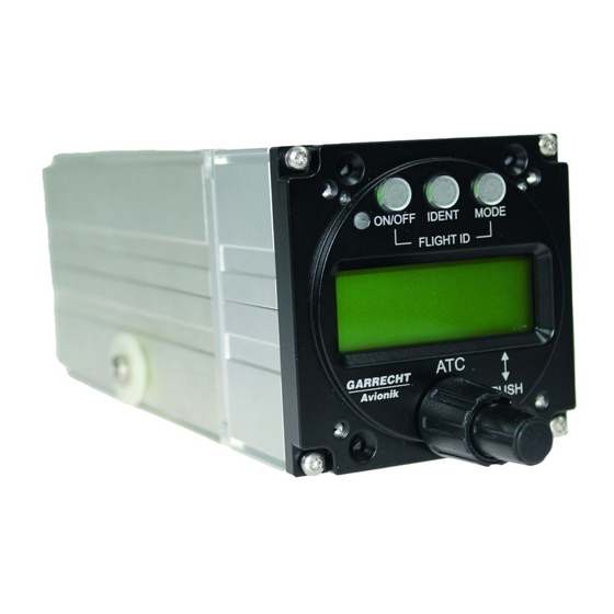
Garrecht Avionik GmbH VT-01 Transponder Installation Manual - english - 01.0200.11E Document: 4.Input Devices (human machine interface) Picture of front panel with Input devices The system will be operated using the following devices: Description Function On/Off key Switches the system On or Off Ident –... -
Page 8: Technical Data And Specifications
Garrecht Avionik GmbH VT-01 Transponder Installation Manual - english - 01.0200.11E Document: 5.Technical data and specifications 5.1.General Technical characteristics Data Mechanical VT-01 Steering unit :65x65x34,5 mm (w/o. connectors) Dimensions Central unit: 65x65x128 mm (w/o. connectors) Mounting 57 mm panel mount... -
Page 9: Certification Base
Garrecht Avionik GmbH VT-01 Transponder Installation Manual - english - 01.0200.11E Document: The system provides 3 buttons and a twinaxle Interfaces: rotary encoder for inputting values and selecting operational modes. System messages and Human machine interface / User input entered values are displayed on a 2 lines / 12 capablity characters LCD display. -
Page 10: Equipment Class
Garrecht Avionik GmbH VT-01 Transponder Installation Manual - english - 01.0200.11E Document: 5.3. Equipment class Class 1: If using central unit VT-0102-()-()-()-125 If using system unit VT-0104-125 Class 2: If using central unit VT-0102-()-()-()-070 If using system unit VT-0104-070 5.4. Mode-S transponder level Level 2se Mode-S transponder 5.5. -
Page 11: Environmental Categories
Garrecht Avionik GmbH VT-01 Transponder Installation Manual - english - 01.0200.11E Document: 5.7. Environmental categories 5.7.1. VT-01 Section Category Conditions Temperature / Altitude D1 Low ground survival temperature 4.5.1 -55° C Low operating temperature 4.5.1 -20° C High ground survival Temperature 4.5.2... -
Page 12: Ultracompact
Garrecht Avionik GmbH VT-01 Transponder Installation Manual - english - 01.0200.11E Document: 5.7.2. VT-01 UltraCompact Section Category Conditions Temperature / Altitude D1 Low ground survival temperature 4.5.1 -55° C Low operating temperature 4.5.1 -20° C High ground survival Temperature 4.5.2 +85°... -
Page 13: Software Level
01.0200.11E Document: 5.8. Software level The software level for VT-01 has been determined to be Level D: Software whose anomalous behavior, as shown by the system safety assessment process, would cause or contribute to a failure of system function resulting in a minor failure condition for the aircraft. -
Page 14: Aircraft Installation
Document: 6. Aircraft installation The VT-01 provides maximum levels of flexibility. Depending on the space in your cockpit you can have a single-block or two-block equipment installation. The two-block system requires a mounting kit/cradle (PN # VT-0103-1-()-() ) to carry the central unit. It allows a quick installation and removal of the complete central unit without using tools. -
Page 15: Panel Mounting
Garrecht Avionik GmbH VT-01 Transponder Installation Manual - english - 01.0200.11E Document: Replace the screws (4-40) in the back of the central unit with quicklock terminals, if installed Rear view of central unit 1. Assemble mating pressure connector and plug for both units in the correct orientation 2. -
Page 16: Wiring
Installation Manual - english - 01.0200.11E Document: The integral alticoder supplies data immediatly after switching on the VT-01. No warm up period is required. For calibration of the internal alticoder, an instruction will be provided by the manufacturer to qualified installers. - Page 17 Garrecht Avionik GmbH VT-01 Transponder Installation Manual - english - 01.0200.11E Document: 6.1.4.1. Connector wiring Wire the female plug to be connected to the connector (CN3) on the back of the central unit as described in the following table. Refer to chapter 17 for a proper cable installation and assembling of the connector.
- Page 18 Garrecht Avionik GmbH VT-01 Transponder Installation Manual - english - 01.0200.11E Document: 6.1.4.2. Power supply The transponder is supplied by the aircrafts’s primary power source (10 V to 28 V DC). The system provides protection against reverse polarity. Always install a Fuse !!! 6.1.4.3.
-
Page 19: Installation Vt-01 - Two-Block
Installation Manual - english - 01.0200.11E Document: 6.2. Installation VT-01 - two-block To install as a two-block system, the following steps need to be performed: Unfasten the 4 Screws (3) and remove the steering unit (1) from the central unit (2). -
Page 20: Installing The Mounting Kit / Cradle
The steering unit contains an integral alticoder. Connect the static pressure line of the aircraft to the connector on back of the steering unit. The integral alticoder supplies data immediatly after switching on the VT-01. No warm up period is required. For calibration of the internal alticoder, an instruction will be provided by the manufacturer to qualified installers. -
Page 21: Wiring
All wires (except antenna line) related to the VT-01 in two-block configuration are connected to several SUB-D 9 pin connectors in the back of the steering unit and the central unit. - Page 22 Garrecht Avionik GmbH VT-01 Transponder Installation Manual - english - 01.0200.11E Document: Wire the female SUB-D 9 plug to be connected to CN1 (back of the steering unit) as described in the following table. Refer to chapter 17 for a proper cable installation and assembling of the connector.
- Page 23 Garrecht Avionik GmbH VT-01 Transponder Installation Manual - english - 01.0200.11E Document: 6.2.4.2. Wiring the connection between the steering unit and the central unit CN2: Use for connecting to the central unit via connector of the mounting kit. Perform a 1:1 connection to the craddle connector: •...
- Page 24 Garrecht Avionik GmbH VT-01 Transponder Installation Manual - english - 01.0200.11E Document: 6.2.4.3. Power supply The transponder is supplied by the aircrafts’s primary power source (10 V to 28 V DC). The system provides a protection against reverse polarity. Always install a fuse !!! 6.2.4.4.
-
Page 25: Cradle Handling
Garrecht Avionik GmbH VT-01 Transponder Installation Manual - english - 01.0200.11E Document: 6.2.5. Cradle handling 6.2.5.1. Inserting the central unit into the cradle Insert the central unit with the antenna connector first in to the cradle. The shoulder washer will slide into the slots in the left and right wall of the cradle. - Page 26 Garrecht Avionik GmbH VT-01 Transponder Installation Manual - english - 01.0200.11E Document: 6.2.5.1.1. Removal of the central unit form the cradle Press the spring lock down and pull the central unit into the direction of the spring lock. When the shoulder washer contact the wall...
-
Page 27: Installation Vt-01 Ultracompact
01.0200.11E Document: 6.3. Installation VT-01 UltraCompact The VT-01 UltraCompact is a very compact size unit with a low weight, that allows installation in small cockpits. General: All installation work shall be performed in accordance with the acceptable methods, techniques and practices for aircraft alterations, inspections and repair, shown in FAA documents AC 43.13-1B and AC 43.13-2A (see www.faa.gov to obtain this documents free of... - Page 28 Document: 6.3.3.1. Connector wiring The VT-01 UltraCompact comes with a prewired connector. Anyway, if modifications on this connector are required or a new connector should be needed, follow the instructions of this chapter Wire the female plug to be connected to the connector (CN3) on the back of the central unit as described in the following table.
- Page 29 Garrecht Avionik GmbH VT-01 Transponder Installation Manual - english - 01.0200.11E Document: 6.3.3.2. Power supply The transponder is supplied by the aircrafts’s primary power source (10 V to 28 V DC). The system provides protection against reverse polarity. Always install a Fuse !!! 6.3.3.3.
-
Page 30: Antenna Installation
Document: 7. Antenna installation 7.1. General Any type of suitable transponder antenna may be used for connection to VT-01. Antenna installation should be done by qualified personal only. It is strongly recommend to follow the step by step instruction below: •... -
Page 31: Antenna Cable
Garrecht Avionik GmbH VT-01 Transponder Installation Manual - english - 01.0200.11E Document: 8. Antenna cable The antenna line connects the RF connector of the transponder to the antenna. For a proper installation, it is recommended to follow the instructions below: •... -
Page 32: Post Installation Configuration And Setup
Garrecht Avionik GmbH VT-01 Transponder Installation Manual - english - 01.0200.11E Document: 9. Post installation configuration and setup 9.1. Setting up pilot specific data 9.1.1. Flight ID / aircraft registration A Mode-S transponder broadcasts the flight id (company callsign for commercial aircraft or the aircraft registration for smaller private operated aircraft). -
Page 33: Display Contrast
Garrecht Avionik GmbH VT-01 Transponder Installation Manual - english - 01.0200.11E Document: 9.1.2. Display contrast • Check, if the transponder antenna has been connected to the device properly • If so, switch on the unit by pressing key 1 •... -
Page 34: Setting Up Password Protected Data
Garrecht Avionik GmbH VT-01 Transponder Installation Manual - english - 01.0200.11E Document: 9.2. Setting up password protected data The input fields for aircraft related data (such as 24-bit Mode-S or aircraft maximum speed) address is password protected to prevent unwanted modifications by unauthorised persons. -
Page 35: Aircraft Data
Garrecht Avionik GmbH VT-01 Transponder Installation Manual - english - 01.0200.11E Document: 9.2.4. Aircraft data All aircraft related data of the following chapters are stored in a profile. If using the system in different aircraft (i.e. balloons), a special firmware feature provides up to five different profiles, that can be selected by the pilot before takeoff. - Page 36 Garrecht Avionik GmbH VT-01 Transponder Installation Manual - english - 01.0200.11E Document: In this case, the following messages appears in the startup screen: Mode-S Addr: confirm this message by pressing <Ident> or <Mode> or push button of rotary encoder INVALID running in confirm this message by pressing <Ident>...
- Page 37 Garrecht Avionik GmbH VT-01 Transponder Installation Manual - english - 01.0200.11E Document: 9.2.4.4. Configuring on ground switch (auto-gnd) The third submenu allows configuring the on ground switch input of the transponder. It needs to be configured, if the unit has been connected to an on-ground switch provided by the airframe.
-
Page 38: Determining Installed Equipment Performance
Garrecht Avionik GmbH VT-01 Transponder Installation Manual - english - 01.0200.11E Document: 10. Determining installed equipment performance In order to comply with EUROCAE ED-73B, it is required to determine equipment performance of the installed equipment. The complete aircraft installation must be certified by authorized personal before operation. - Page 39 Garrecht Avionik GmbH VT-01 Transponder Installation Manual - english - 01.0200.11E Document: passed Altitude Reporting test General: A sufficient number of test points should be checked to ensure that the altitude reporting equipment and transponder perform their intended function through their entire range while ascending or descending.
-
Page 40: Flight Test Procedures
Garrecht Avionik GmbH VT-01 Transponder Installation Manual - english - 01.0200.11E Document: 10.3. Flight test procedures 10.3.1. General This guidance material offers examples of flight test procedures for demonstrating selected performance functions. Flight demonstration of installed performance may be required to determine the performance and characteristics of the installed antenna. -
Page 41: Appendix A - Dimensions
Garrecht Avionik GmbH VT-01 Transponder Installation Manual - english - 01.0200.11E Document: Appendix A - Dimensions VT-01 Steering unit and System unit Revision: 1.3... -
Page 42: Mounting Kit (With Craddle)
Garrecht Avionik GmbH VT-01 Transponder Installation Manual - english - 01.0200.11E Document: VT-01 Mounting kit (with craddle) Revision: 1.3... -
Page 43: Ultracompact
Garrecht Avionik GmbH VT-01 Transponder Installation Manual - english - 01.0200.11E Document: VT-01 UltraCompact Revision: 1.3... -
Page 44: Appendix B
Garrecht Avionik GmbH VT-01 Transponder Installation Manual - english - 01.0200.11E Document: Appendix B Template for panel cutout Revision: 1.3... -
Page 45: Assembling Bnc/Tnc Plugs For Aircell 7 Coaxial Cable
Garrecht Avionik GmbH VT-01 Transponder Installation Manual - english - 01.0200.11E Document: Appendix C Assembling BNC/TNC plugs for AIRCELL 7 coaxial cable Revision: 1.3... -
Page 46: Assembling The Sub-D Connectors For Interconnection Wiring
Garrecht Avionik GmbH VT-01 Transponder Installation Manual - english - 01.0200.11E Document: Assembling the Sub-D Connectors for interconnection wiring For a proper shielding of the interconnection wiring, follow these steps: • Remove the outer insulation of the interconnection cable (65mm/2.5"") •... - Page 47 Garrecht Avionik GmbH VT-01 Transponder Installation Manual - english - 01.0200.11E Document: • Flip the conductive aluminium tape braid, which has former been flipped over the outer insulation. • Install the hood cable clamps as shown in this and the following picture •...
- Page 48 Garrecht Avionik GmbH VT-01 Transponder Installation Manual - english - 01.0200.11E Document: • Insert the cable with the cable clamp into the hood as shown. • Cut all pairs and the wire made of the braid to appropriate length for installation of a Sub-D Connector (not shown in this picture).
Need help?
Do you have a question about the VT-01 and is the answer not in the manual?
Questions and answers