Advertisement
Advertisement
Table of Contents

Related Manuals for Audio Legion AL6500.1D


Summary of Contents for Audio Legion AL6500.1D
- Page 1 Owner’s Manual AL6500.1D AL8500.1D MADE IN KOREA Manual size : 150 x 210mm...
-
Page 2: Installation
Installation In case you install the amplifier by yourself, please read the user manual carefully and follow the outlined instructions. Mounting Preparation Disconnect the negative (-) battery cable before mounting or making any connections. Check the battery and alternator ground (-) connections. Make sure they are properly connected and free of corrosion. -
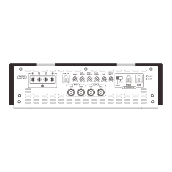
Page 3: Panel Layout
Panel Layout (AL6500.1D / AL8500.1D) BASS BASS PHASE REMOTE GAIN SONIC BOOST FREQ. SHIFT SPEAKER OUTPUTS 0.2V 10Hz 70Hz 12dB 30Hz 90Hz 30Hz 250Hz SLAVE MASTER SLAVE INPUT OUTPUT MASTER OUTPUT INPUT DAISY-CHAIN 1) INPUT Connect preamp signal cables from head unit to RCA input of the amplifiers. - Page 4 +12V(B+), GND, REM (AL6500.1D) +12V +12V POWER INPUT A POWER INPUT B PT LINK (AL8500.1D) +12V +12V +12V POWER POWER POWER INPUT-B INPUT-A INPUT-C PT LINK GND (GROUND CONNECTION) For connection to the chassis ground. For optimum performance 0 gauge cable is recommended.
-
Page 5: Single Connection
+12V ), GND, REM Connection (AL6500.1D) GROUND SINGLE CONNECTION * Keep ground as short as possible, no longer than 20” (50 cm). +12V +12V POWER INPUT A POWER INPUT B PT LINK BATTERY Remote turn on HEAD UNIT GROUND Recommended Fuse Rating... - Page 6 +12V ), GND, REM Connection (AL8500.1D) GROUND SINGLE CONNECTION * Keep ground as short as possible, no longer than 20” (50 cm). +12V +12V +12V POWER POWER POWER INPUT-B INPUT-A INPUT-C PT LINK BATTERY Remote turn on HEAD UNIT GROUND Recommended Fuse Rating (See page 10) * Keep ground as short as possible,...
-
Page 7: Speaker Connection
Speaker connection (AL6500.1D / AL8500.1D) SINGLE CONNECTION BASS BASS PHASE REMOTE GAIN SONIC BOOST FREQ. SHIFT SPEAKER OUTPUTS 0.2V 10Hz 70Hz 12dB 30Hz 90Hz 30Hz 250Hz SLAVE MASTER SLAVE INPUT OUTPUT MASTER OUTPUT INPUT DAISY-CHAIN Speaker Impedance 1~8 ohms HEAD UNIT... -
Page 8: Troubleshooting
3. Our amplifiers have a high voltage protection. Make sure that the operating voltage is between 8.5V~ 16V (8.5V~18V : AL6500.1D) and voltages above this range will cause the amplifier to go into protect. Protect LED is on 1. -
Page 9: Specifications
Specifications MODEL CODE AL6500.1D Continuous power output @14.4V Input -RMS power, 4 ohms mono : 1625W x 1CH -RMS power, 2 ohms mono : 3250W x 1CH -RMS power, 1 ohm mono : 6500W x 1CH Signal to noise ratio : >100dB... - Page 10 Specifications MODEL CODE AL8500.1D Continuous power output @14.4V Input -RMS power, 4 ohms mono : 2125W x 1CH -RMS power, 2 ohms mono : 4250W x 1CH -RMS power, 1 ohm mono : 8500W x 1CH Signal to noise ratio : >100dB Low pass frequency crossover : 30Hz~250Hz...
- Page 12 MADE IN KOREA...
Need help?
Do you have a question about the AL6500.1D and is the answer not in the manual?
Questions and answers