Advertisement
Advertisement
Table of Contents

Summary of Contents for Top Gun PREDATOR
- Page 1 Downloaded from www.cbradio.nl...
-
Page 2: Table Of Contents
CONTENTS FUNCTIONS & FEATURES ..............1 STANDARD ACCESSORIES ...............2 OPTIONAL ACCESSORIES..............2 INSTALLATION ..................2 GETTING ACQUAINTED ..............6 HOW TO USE YOUR RADIO ...............8 SLIDE SWITCHES ................9 ERROR CODE ..................10 SPECIFICATIONS ................11... -
Page 3: Functions & Features
FUNCTIONS & FEATURES ◆ FM/AM/PA mode ◆ Weather Channel 150-170MHz programmable ◆ CTCSS/DCS Code(Optional) ◆ Analog S/RF Meter + Digital SWR Meter ◆ PC programmable ◆ Dual Echo Controls ◆ SQ, ASQ Function ◆ RF Gain Adjustment ◆ Mike Gain Adjustment ◆... -
Page 4: Standard Accessories
STANDARD ACCESSORIES Radio Mounting Bracket Microphone Non-slip Microphone Hanger DC Power Screws for Pads for Adjusting Spare Fuses Self-tapping Pads Cable bracket bracket screws Screws (10A,250V) OPTIONAL ACCESSORIE USB Programming External Speaker Cable INSTALLLATON Choose the most appropriate location from a simple and practical point of view. -
Page 5: Installation
Microphone connection 1. Plug microphone connector into jack. 2. Pull on the screw for microphone connector. RX/TX RX/TX RF PWR BAND RF PWR BAND NB/ANL NB/ANL DATA DATA ` $ T ` $ T E VOL E DLY PA FM PA FM E VOL E DLY... - Page 6 1. Connect positive red power cable with the + terminal of the battery. 2. Connect negative black power cable with the - terminal of the battery. 3. Connect the DC power cable to the transceiver's power supply connector. ▲ If a cigarette lighter is used, use one rated for at least 10 Amps. ▲...
- Page 7 Install Microphone Hanger Choose a ideal location which will not interfere the driver. Using supplied self-tapping screws and pads(2 sets) to fix the hanger. Install External Speaker If use an external speaker, please choose 8ohm speaker with 3.50mm mono band (doulbe cable) plug.
-
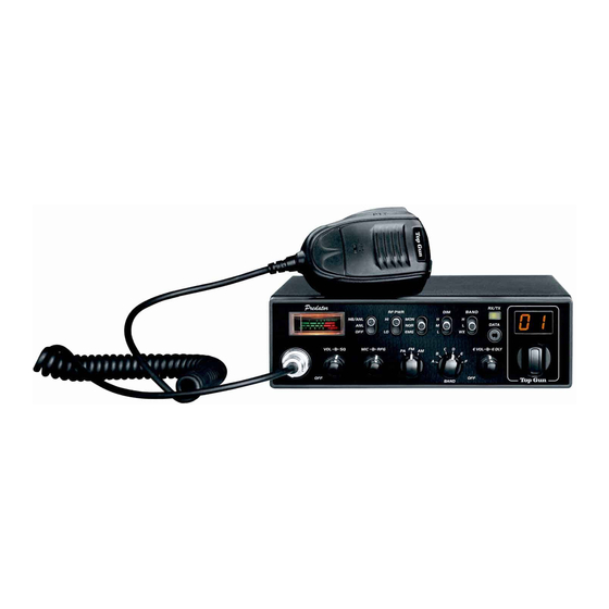
Page 8: Getting Acquainted
GETTING ACQUAINTED Front Panel RX/TX RF PWR BAND NB/ANL DATA ` $ T PA FM E VOL E DLY BAND No. Functions S/RF Meter Control NB/ANL function on/off Control power level Monitor (Talk-Back) level control/EMG Control LED brightness Choose H and L band group TX/RX indicator PC programming port Channnel &... - Page 9 Rear Panel ANT. PA.SP. EXT.SP. POWER Functions External Speaker Jack PA Speaker Jack Antenna Jack Power Supply Jack Microphone Channel Down Channel UP Connector Microphone cable...
-
Page 10: How To Use Your Radio
HOW TO USE YOUR RADIO OFF/ON Radio 1. Turn VOL clockwise to switch on the radio, the radio will emit a beep. When the LED displays frequency or channel, the radio is on. 2. Turn VOL anti-clockwise to switch off the radio, the radio is OFF when hear a Click from the switch. -
Page 11: Slide Switches
SLIDE SWTICH Function Position Description NB/ANL Trun on NB and ANL function NB/ANL NB/ANL Turn on ANL fucntion NB/ANL Turn off NB/ANL fucntion Set on high RF power AM: 10W FM: 10W RF Power Set on super RF power AM: 10W FM: 40W Set on low RF power AM: 4W FM: 4W Choose Monitor level. -
Page 12: Error Code
ERROR CODE When the RX/TX indicator light is yellow, LED displays code means the radio has problem. E1: Voltage too low E2: Voltage too high E3: WX function invalid E4: Current BAND invalid E5: TX SWR too high... -
Page 13: Specifications
SPECIFICATIONS GENERAL Frequency Range 28.000-29.695MHz(Programmable) Frequency Band L band: A/B/C/D/E/F H band : A/B/C/D/E/F Channel 40 channels(programmable) in each band Frequency Control Phase-Locked-Loop Synthesizer Frequency Tolerance ± 5.0 ppm Temperature Range -20℃to +50℃ Microphone with push-to-talk /UP/DN and coiled cord Input Voltage 13.8V Dimensions (in mm) - Page 14 RECEPTION AM: 1.0μV for 10dB(S+N)/N at greater than 1/2 watt of audio output Sensitivity FM: 1.0μV for 20dB(S+N)/N at greater than 1/2 watt of audio output Adjacent-Channel Selectivity AM/FM: 60dB Image Rejection More than 65dB IF Frequency AM/FM: 10.695MHz 1st IF, 455KHz 2nd IF RF Gain Control 45dB adjustable for optimum signal reception Less than 10dB change in audio output for inputs...
- Page 15 Top Gun Technologies www.TopGunTec.com...
Need help?
Do you have a question about the PREDATOR and is the answer not in the manual?
Questions and answers