Table of Contents
Advertisement
Quick Links
Advertisement
Table of Contents

Summary of Contents for Argus RSM 48 UPF
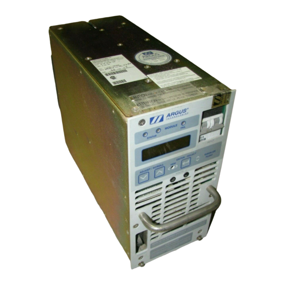
- Page 1 RSM 48/50 UPF Modular Switched Mode Rectifier 010-511-B2...
- Page 2 Argus Technologies Ltd. Visit www.argus.ca Burnaby, British Columbia. Telephone: 604 436 5900 Fax: 604 436 1233 Argus Technologies reserves the right to make changes to the products and information contained in this document without notice. ® Copyright 2008 Argus Technologies Ltd. Argus is a registered trademark of Argus Technologies Ltd.
- Page 3 • Installation and Operation Instructions: 010-030-C0 Rev E • Factory Service Information: 048-527-10 (Patent #: 5,379,206) Argus Technologies Ltd. 010-511-B2 Rev B WC Printed in Canada. © 2006 Argus Technologies Ltd. ARGUS and UNITY SERIES are trademarks of Argus Technologies Ltd. All Rights Reserved.
- Page 4 SPECIFICATIONS FOR ARGUS TECHNOLOGIES’ SWITCH MODE RECTIFIER RSM 48/50 (UPF) Output Voltage: 42 - 62 VDC (test) 50 - 60 VDC (equalize) 48 - 57 VDC (float) Current: 50 Amps DC nominal Power: 3000 Watts continuous/module Regulation: +/- 0.02% line and load (static, zero slope) <1% deviation for 50 to 100% load step (dynamic)
- Page 5 4 Module Shelf: 16 kg (36 lb.) 3 Module Shelf: 14 kg (31 lb.) Module: 12 kg (26 lb.) Acoustic Noise: 60 dBa at 1m (3 ft) Alarm/Control Connections: 60 VDC, 0.5 A maximum ARGUS TECHNOLOGIES 010-511-B1 Rev A Page 2 of 3...
- Page 6 * N/R — Not recommended. Connecting 4 equivalent loads to a three phase source in delta configuration will create an unbalanced load. It’s usually more feasible to run a sepa- rate #10 AWG line directly to the 4th module. (Specifications subject to change without notice) ARGUS TECHNOLOGIES 010-511-B1 Rev A Page 3 of 3...
- Page 7 US and Canadian markets, to the applicable US and Canadian standards. (1) Argus rectifier and power system products, bearing the aforementioned CSA marks, are certified to CSA C22.2 No. 950 and UL 1950, or CSA/UL 60950.
- Page 8 “ ADDNEW.DOC” INCLUDED WITH DOCUMENT 022-000-C1. EXPLANATION: The market shift from vented or “ wet cell” to valve regulated lead acid (VLRA) batteries has prompted Argus to update its factory default settings to accomodate the requirements of these batteries. The changes listed below are being implemented immediately as new factory default settings in all Argus power products.
- Page 9 MANUAL ADDENDUM Function 24 volt systems (nom) 48 volt systems (nom) Float TABLE 1-3: RSM 48/7.5 and 24/15 SUPERVISORY/CONTROL MODULE Function 24 volt systems (nom) 48 volt systems (nom) TABLE 1-4: SUPERVISORY/CONTROL SYSTEMS (SD-02,03,04,05) Function 12 volt systems (nom) 24 volt systems (nom) 48 volt systems (nom) 10.5 Load Out...
- Page 10 IMPORTANT SAFETY INSTRUCTIONS SAVE THESE INSTRUCTIONS - This manual contains important safety and operating instructions for battery charger models RSM 48/50, RSM 48/30, RSM 24/100, RSM 24/50. Caution - Do not install or remove any modules with the input breaker or output breaker in the closed position. Before using battery charger, read all instructions and cautionary markings on: (1) battery charger, (2) battery, and (3) product using battery.
-
Page 11: Table Of Contents
Installation and Operator's Manual for RSM series of Modular Switched Mode Rectifiers Table of Contents Warranty Documentation - Part number information....................1 Introduction..........................1 ARGUS Numbering system ......................1 General..............................2 Scope ............................2 Introduction..........................2 Features ............................2 3.3.01 LCD Display and Control Keys ..................2 3.3.02 Status Mode Indicators ....................6 3.3.03 Status Indicator - Module OK ..................6... - Page 12 7.6.1 Slope Control - RSM units in parallel with variable slope units ........32 7.6.2 Slope Control - Argus units in parallel with fixed slope units ........32 7.6.3 Forced Paralleling - Argus RSM units in parallel with other RSM units......32 Start Delay ..........................33 High Output Voltage Shutdown ....................33...
- Page 13 8.1.5 Communicating with the RSM ..................39 8.1.6 Access to the RSM ......................40 8.1.6.1 Remote Access/Lockout ................40 8.1.6.2 Remote Adjust Access/Lockout ..............40 Module ID............................41 Baud Rate ...........................41 Remote Disable...........................41 Remote Adjust Disable .......................41 Remote status / control..........................42 Remote Terminal Status Format..................42 List of Figures and Tables Figure 1 - Front Panel (RSM-48/30, RSM-24/50) ...................3 Figure 2 - Front Panel (RSM-48/50, RSM-24/100) .................3...
- Page 14 Hongli Industrial Area, Miaobian, Liaobu Town, Dongguan City, Guangdong Province, 523400 China Argus shall not be liable to the customer or other parties for any loss of profits, loss of use, costs for Tel: +86 755 8895 3310 Fax:...
-
Page 15: Documentation - Part Number Information
BOLD UPPERCASE typeface. ARGUS Numbering system ARGUS technologies uses a eight digit drawing number system which is broken into three blocks. The first three digits describe the category of the product ie. rectifier or fuse panel. The next three digits indicate the sequence in which the product number was allocated in a particular category. -
Page 16: General
General Scope This instruction manual covers the installation, and operation of Argus Technologies' RSM 48/100 switched mode rectifier. Introduction The RSM series of rectifiers employs a high frequency switched mode conversion technique to pro- vide a fully regulated and isolated DC output from the A.C. mains. The unit provides external con- nections for input, output and alarm interfaces. - Page 17 Figure 1 - Front Panel (RSM-48/30, RSM-24/50) Figure 2 - Front Panel (RSM-48/50, RSM-24/100) (NOTE: View hole may or may not be present) ARGUS TECHNOLOGIES 010-030-C0 Rev E Page 3 of 42...
- Page 18 Due the limited number of characters that can be displayed, abbreviated messages are used. The manual uses both abbreviated and complete condition descriptions. See Table #1 for display mes- sage abbreviations. 010-030-C0 Rev E Page 4 of 42 ARGUS TECHNOLOGIES...
- Page 19 STATUS ............enter status menu STRT DELAY = XXXsec .......display start delay time TEMP DISPL DEG C/F ........adjust temperature display mode TEST MODE ..........enter test mode menu Table 1 - Display Messages ARGUS TECHNOLOGIES 010-030-C0 Rev E Page 5 of 42...
-
Page 20: Status Mode Indicators
EQUALIZE. FLOAT mode is indicated by illumination of the FL beside the output voltage reading on the LCD display. The level is protected by fail safe circuitry in the un- likely event of micro-controller failure. 010-030-C0 Rev E Page 6 of 42 ARGUS TECHNOLOGIES... -
Page 21: Float Mode
The H.V. shutdown does not require manual reset as it will restart automatically. AUTO TEST is aborted if the output breaker is closed during the process. When the mode is exited the module will return to the previous output mode ie. FLOAT. ARGUS TECHNOLOGIES 010-030-C0 Rev E Page 7 of 42... -
Page 22: Auto Test - Units With High Output Alarm Feature
The following conditions will generate a minor alarm: Low Output Voltage High Output Voltage Over Temperature Fan Fail Test Mode Adjust Mode Remote Mode Temperature Sensor Failure UPF High Temperature 010-030-C0 Rev E Page 8 of 42 ARGUS TECHNOLOGIES... -
Page 23: True Module Fail Alarm
If the current limit level is adjusted during a fan failure, the unit will reset to the new setting after the fan failure has been corrected. This feature is implemented on all RSM-48/50, RSM-24/100, RSM-48/30, and RSM-24/50 modules with software version 2.30 or later. ARGUS TECHNOLOGIES 010-030-C0 Rev E Page 9 of 42... -
Page 24: Over Voltage Shutdown
FLOAT mode. The duration for the delay is set by the setting found in the submenu AD- JUSTMENTS. When active the message DELAY START and the time remaining will be displayed on the LCD panel. 010-030-C0 Rev E Page 10 of 42 ARGUS TECHNOLOGIES... -
Page 25: Soft Start
If the temperature sensor fails at the same time as the fan, then the current limit will be set to 50% of maximum rated current. ARGUS TECHNOLOGIES 010-030-C0 Rev E Page 11 of 42... -
Page 26: Battery Eliminator Operation
This approach enables retention of user level programming during periods of inactivity such as transportion of the modules. Levels may also be preset at a central service area before shipment to the field. 010-030-C0 Rev E Page 12 of 42 ARGUS TECHNOLOGIES... -
Page 27: Over Temperature Alarm
50% in very abnor- mal circumstances. The front panel will display the message UPF HI TEMP to indicate this abnor- mal condition. ARGUS TECHNOLOGIES 010-030-C0 Rev E Page 13 of 42... -
Page 28: Installation Instructions
- Adjustable resistive load 24/48 volts Inspection All Argus products are shipped in rugged, double walled boxes and suspended via solid polyure- thane foam inserts to minimize shock that may occur during transportion. Packaging assemblies and methods are tested to National Safe Transit Association standards. -
Page 29: Module Shelf
Module's A.C. input breaker. The size of the feeder breaker will be dependent on whether it is a single phase or three phase source. See specifications for recom- mended feeder protection. ARGUS TECHNOLOGIES 010-030-C0 Rev E Page 15 of 42... -
Page 30: Figure 6 - Shelf Connections (Rsm-48/50 & 24/100 Shelf)
Figure 6 - Shelf Connections (RSM-48/50 & 24/100 Shelf) Figure 7 - Shelf Connections (RSM-48/30 & 24/50 Shelf) Figure 8 - 1 Phase Hookup 010-030-C0 Rev E Page 16 of 42 ARGUS TECHNOLOGIES... -
Page 31: A.c. Connections
Right Side - Blank Plate Standard AC cable knock outs for the 4 Module RSM 48/50 & 24/100 shelves are: Left Side - 1-1/2" knock out Right Side - Blank Plate ARGUS TECHNOLOGIES 010-030-C0 Rev E Page 17 of 42... -
Page 32: Output Connections
The current limiting capac- ity of the battery system can be aided by selecting the minimal wire size without compromising the maximum loop voltage drop. 010-030-C0 Rev E Page 18 of 42 ARGUS TECHNOLOGIES... -
Page 33: Figure 10 - Alarm/Control Connections (Rsm 48/50 & 24/100)
Module Fail 3 TB5-15 TB5-16 P23 (2-3) TB5-16 P23 (1-2) Module Fail 4 TB5-17 TB5-18 P24 (2-3) TB5-18 P24 (1-2) Table 2 - TB5 Connections & Jumpers (RSM 48/50 & 24/100) ARGUS TECHNOLOGIES 010-030-C0 Rev E Page 19 of 42... -
Page 34: Figure 11 - Alarm/Control Connections (Rsm 48/30 & 24/50)
TB3-10 P25 (2-3) Module Fail 4 TB3-11 (only on cabinets TB3-12 P26 (1-2) with 4 modules) TB3-12 P26 (2-3) Table 3 - TB1, TB2, TB3 Connections & Jumpers (5KW & 7KW) 010-030-C0 Rev E Page 20 of 42 ARGUS TECHNOLOGIES... -
Page 35: Output Connections
Refer to Figure #12 . WARNING: Ensure that the polarity of the output of the cabinet and the sense lines (if used) are correct. Verify polarity using a hand held voltmeter. :WARNING ARGUS TECHNOLOGIES 010-030-C0 Rev E Page 21 of 42... - Page 36 Figure 12 - DC Output Connections WARNING: Over tightening of the post nuts may result in damage to the unit. :WARNING Figure 13 - Vertical Bus Bar Adaptor (RSM 48/50 & 24/100) 010-030-C0 Rev E Page 22 of 42 ARGUS TECHNOLOGIES...
-
Page 37: Output Bus Bars
Output Bus Bars For high current applications (above 200 Amps) the output can be connected directly to 1/4" x 2" vertical charge bus bars with a bus bar adaptor kit (Argus P/N 020-508-20). Install the bus bar adaptors per Figure #13 . -
Page 38: Initial Start-Up
Check the current setting by scrolling through the adjustment menu until the current level is displayed. Use the same process described for float setting to adjust the output current limit point. 010-030-C0 Rev E Page 24 of 42 ARGUS TECHNOLOGIES... - Page 39 Figure 14 - Display Adjustment Sequence and Syntax ARGUS TECHNOLOGIES 010-030-C0 Rev E Page 25 of 42...
-
Page 40: Output High Voltage Protection (Initial)
Paralleling: Slope or Forced The user has the ability to select either forced paralleling or slope methods of load sharing. If all units are Argus RSM series then forced paralleling should be used. If selected the modules will track automatically. -
Page 41: Negative Slope Paralleling
4.6.6.1 Negative Slope Paralleling When the unit is used in a multi-Module configuration with non Argus RSM series units then the slope method should be used. The output slope adjustment should be given a preliminary adjust- ment so that the Modules will share the load. Set the slope controls of all units to 1.00% via the slope adjustment submenu of LOAD SHARING found in the ADJUSTMENTS menu. -
Page 42: Operation
The receipt of a remote equalize signal will put the unit in into equal- ize and the message REMOTE EQUALIZE will be displayed on the front panel display. Upon re- moval of the signal, the unit will return to the FLOAT mode. 010-030-C0 Rev E Page 28 of 42 ARGUS TECHNOLOGIES... -
Page 43: Status Mode - Local
If the AC input breaker in the module is open and there is DC power at the output ter- minals (output DC breaker closed), then the heatsink temperature will be unavailable and will read N/A. The internal ambient temperature will still read correctly. ARGUS TECHNOLOGIES 010-030-C0 Rev E Page 29 of 42... -
Page 44: Adjustments
AC Mains voltage is outside the range stated in the specifications. Final adjustments should be done only when the unit has reached operating temperature. Warm-up of 15 min- utes is sufficient. :WARNING 010-030-C0 Rev E Page 30 of 42 ARGUS TECHNOLOGIES... -
Page 45: Float Voltage
TEST submenu . Manual tests requires the operator to vary the level via the adjustment keys. Auto tests automatically ramps the test voltage to confirm alarm levels. ARGUS TECHNOLOGIES 010-030-C0 Rev E Page 31 of 42... -
Page 46: Load Sharing Parallel Operation
In order to see if the Argus units are set at a slope that matches the fixed slope units, it is neces- sary to vary the load by using a variable resistive load (for non-battery type loads) or by turning off the A. -
Page 47: Start Delay
The control is overridden by the remote equalize signal. Us- ing the up and down adjustment keys alters the time from 1 to 30 hours. ARGUS TECHNOLOGIES 010-030-C0 Rev E Page 33 of 42... -
Page 48: Back Light Time-Out
UP or DOWN keys until the desired number is displayed and the EN- TER/SELECT key is pressed. The display will wrap around from 9 to 0 (or 0 to 9) when the Up (or Down) key is pressed. 010-030-C0 Rev E Page 34 of 42 ARGUS TECHNOLOGIES... -
Page 49: Remote Access
9 PIN to 9 PIN straight through cable although only pins 1,2,4 and 5 need be connected. Argus part #877-012-10 is recommended for interconnecting the cabinets. Connect the cable from 1 connector labeled RS485 to another connector labeled RS485 on the next shelf. -
Page 50: Rs232 Interface
9-pin serial cable - it will not work. RS232 Interface Cable (9 pin SCI to 25 pin RS232 or 9 pin RS232) Connected To Cable Length Argus Part Numbers Modem - DB25 (DCE) 6/12/25 ft 877-006-10... -
Page 51: Modem Connection
Set the necessary switch such that the modem will power up in automatic answer mode. c) Set the necessary switch such that the modem will operate at the desired baud rate (see section 8.1.3.2) ARGUS TECHNOLOGIES 010-030-C0 Rev E Page 37 of 42... - Page 52 The consequence of using a modem that does not power up in auto answer mode is that if the power to the modem is interrupted and resumed, a remote caller will not be able to call into the RSM cabinet. The baud rate settings may also be affected. 010-030-C0 Rev E Page 38 of 42 ARGUS TECHNOLOGIES...
-
Page 53: Local Terminal Connection
PROCOMM or LYNC. LYNC, a publicly available shareware program, is available free of charge from Argus and is pre-configured to work with the SCI board. When you use other terminal pro- grams such as PROCOMM, a few settings have to be made. The local echo (also called half du- plex) setting should be set ON so the user can see what is typed on the screen. -
Page 54: Access To The Rsm
When REMOTE ADJUST is locked out, the RSM simply ignores the UP, DOWN, and ENTER com- mands and responds with REMOTE LOCKOUT. The module will only provide status information through the STATUS command. 010-030-C0 Rev E Page 40 of 42 ARGUS TECHNOLOGIES... -
Page 55: Module Id
Remote Adjust Disable Depending on factory programming some units are able to receive remote adjustment of all levels similar to local operation. Consult factory for complete information on the operation of this feature. ARGUS TECHNOLOGIES 010-030-C0 Rev E Page 41 of 42... -
Page 56: Remote Status / Control
AC MAINS HIGH FAN FAIL MODULE FAIL OVER TEMPERATURE O/P HV SHUTDOWN LOW O/P VOLTAGE CURRENT LIMIT TEMP SENSE FAIL FAN SPEED ERROR UPF HIGH TEMPERATURE Figure 17 - Remote Screen Layout 010-030-C0 Rev E Page 42 of 42 ARGUS TECHNOLOGIES... - Page 57 This page intentionally left blank.
- Page 58 Technical support staff are available for answering general questions related to installation, operation Argus Technologies Ltd. ATTN: RMA Returns and maintenance of Argus products. In Canada and the USA, call Argus toll free 7:30 am to 5:00 pm 7033 Antrim Avenue Pacific Standard Time at:...
Need help?
Do you have a question about the RSM 48 UPF and is the answer not in the manual?
Questions and answers