
Related Manuals for Wahlberg Winch 50 Double

Summary of Contents for Wahlberg Winch 50 Double
- Page 1 Axel Gruhns Vej 3 DK-8720 Højbjerg DENMARK WWW.WAHLBERG.DK Winch 50 Double Item No 246.702 User Manual WWW.WAHLBERG.DK · TELEPHONE +45 86 18 14 20 · EMAIL: sales@wahlberg.dk...
-
Page 2: Safety Information
If you have questions about how to operate the winch safely, please contact you Wahlberg Motion Design supplier or Wahlberg Motion Design. PROTECTION FROM ELECTRIC SHOCK −... -
Page 3: Index
Allow the winch to cool for at least 10 minutes before handling. − Do not modify the winch in any way not described in this manual. − Install only genuine Wahlberg parts. PROTECTION FROM INJURY − Fasten the winch securely to a fixed surface, rig, or structure when in use. The winch is not portable when installed. - Page 4 Disposing of this product Wahlberg Motion Design products are supplied in compliance with Directive 2002/96/EC of the European Parliament and of the Council of the European Union on WEEE (Waste Electrical and Electronic Equipment), as amended by Directive 2003/108/EC, where applicable.
-
Page 5: Table Of Contents
Index SAFETY INFORMATION INDEX TECHNICAL SPECIFICATIONS INTRODUCTION ............................ 7 ACKAGE CONTENT ............................. 7 ESCRIPTION .............................. 8 REA OF USE ......................... 8 SING FOR THE FIRST TIME PHYSICAL INSTALLATION ....................9 ASTENING THE WINCH TO A FLAT SURFACE AC POWER ............................. 10 OWER VOLTAGE ...................... -
Page 6: Technical Specifications
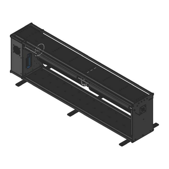
Technical specifications Model: Winch 50 Double Item no.: 246.702 Dimensions: 1644 × 298 × 445 mm / 64.7 × 11.7 × 17.5 in. (L×W×H) Power supply: 210-240V AC 50-60 Hz. Power consumption: 500 Watt. Power plug: Neutrik powerCON TRUE1 NAC3PX DMX control signal: DMX 512 1990 + DMX512A / 6 channels used. -
Page 7: Introduction
It lifts props and small set pieces in and out of the stage sphere at maximum load of 50 kg up and down. The lifting height is 40 m. Contact Wahlberg Motion Design for extending your lifting height. The lifting speed is between 9 cm/s and 45 cm/s. -
Page 8: Area Of Use
Do not modify the winch. For any modification of your winch, contact Wahlberg. It is the customers' responsibility that any local restrictions concerning the use of the winch are complied with. -
Page 9: Physical Installation
Physical installation Warning! The Winch 50 must be either fastened to a flat surface such as a roof, or clamped to a truss or similar structure in such a way that the wire exit points downwards. Do not apply power to the Winch 50 if it is not securely fastened. Fastening the winch to a flat surface The Winch 50 can be fastened to flat surface such as a roof. -
Page 10: Ac Power
AC mains power input. The cable must meet the requirements listed under “Protection from electric shock” on page 2. Wahlberg Motion Design can supply the PowerCON input connector without a cable. If you install a power plug on the power cable, install a grounding-type (earthed) plug that is rated 20 A minimum. -
Page 11: Installing A Power Input Connector On A Power Cable
Installing a power input connector on a power cable To install a Neutrik powerCON TRUE1 NAC3FX-W input connector on a power Cable, follow the original Neutrik instructions below: 246.805.201 Date: 2017-09-26... - Page 12 246.805.201 Date: 2017-09-26...
-
Page 13: Data Link
Data link A DMX 512 data link is required in order to control the winch via DMX. The Winch 50 has 5-pin XLR connectors for DMX data input and output. The pin-out on all connectors is pin 1 = shield, pin 2 = Data (-), and pin 3 = Data (+). Pins 4 and 5 in the 5-pin XLR connectors are not used in the Winch 50 but are available for possible additional data signals as required by the DMX512-A standard. -
Page 14: Lifting Wire Power And Data Link
Lifting wire power and data link Warning! Read “Safety Information” on page 2 before connecting AC mains power to the lifting wire. Warning! Socket outlets or external power switches used to supply the lifting wire attachment with power must be located near the winch and easily accessible so that the lifting wire attachment can easily be disconnected from power. -
Page 15: Emergency Stop Switch (Optional)
Emergency stop switch (Optional) The Winch can be configured with an emergency stop Warning! By default the emergency stop is NOT enabled! If the emergency stop switch is activated (pin 1 and pin 4 are disconnected) the red ERROR LED will light. The emergency stop switch is connected to the male 4 pole XLR connector. - Page 16 Then inside the unit there is an orange wire that needs to be set correctly for operation with/without emergency stop. Emergency stop disabled Emergency stop enabled When the emergency stop is enabled and the little piece of orange wire is not connected it is recommended that it is secured in some way so it does not hit anything.
-
Page 17: Lifting Wire Power
Lifting wire power Warning! Read “Safety Information” on page 2 before connecting AC mains power to the lifting wire. Warning! Socket outlets or external power switches used to supply the lifting wire attachment with power must be located near the winch and easily accessible so that the lifting wire attachment can easily be disconnected from power. -
Page 18: Setup
Winch 50. Warning! Before running the winch, it is important to put a counterbalance on the wire. Warning! Only experienced DMX users should operate the winch. Contact Wahlberg for further information and education on DMX protocol. Counterbalance When the winch has been mounted, it is important to mount a counterbalance before running with it. - Page 19 MENU - DMX CONTROL: Go back to the starting position and activate DMX control The top line of the display is showing: Push the buttons UP & DOWN and hold them for 3 seconds. Now the top line of the display is showing: Navigate the menu The top line of the display is showing: Push the buttons UP or DOWN to go up and down in the menu choices.
-
Page 20: Dmx Address Setting
Use the arrows ↑ and ↓ to adjust the DMX ADDR. Save changed value The display shows: Push ENT to change the top line to: Where X is an increasing number from 1 to 20. Then press and hold ENT The top line of the display counts up to 20 then shows OK. - Page 21 channel Function Description Position This channel controls the position of the winch, with the speed (DMX channel 3). rough This rough position works together with the fine position (DMX channel 2). The rough position and the fine position are multiplied in to a 16 bit channel. The rough position is the MSB.
-
Page 22: Adjusting Limit Switches
Adjusting limit switches Just under the drum there is a small black box. When you take the lid of this box the limits can be adjusted. The limits are adjusted by turning the screws. 1. Loosen the middle screw. 2. Bottom limit is adjusted by turning the screw with a 1 next to it. 3. -
Page 23: Adjustable Parameters
Adjustable parameters Menu Description Range Default MAN SPEED Speed for manual driving 200 – 2500 MAN UP/DWN Run the motor manual from the menu MOTOR UP / MOTOR DOWN DMX ADDR DMX start address 1-506 TAC RANGE Tacho range 1-50,000 SPEED MAX Maximum speed 500-3,500... -
Page 24: Normal Operation
Normal Operation Temperatures If the surface temperature of the winch exceeds 90°C (194°F) there is a risk of damaging the winch. Duty cycle The winch should not be operated at a duty cycle higher than 30% for longer periods of time. -
Page 25: Led Functions
LED Functions DMX LED The DMX lamp will be steady green when receiving a DMX signal. The DMX lamp will flash green if no DMX signal is present. Error LED The error LED will light red if there is an error. Reset error is done by setting DMX channel 4 to 0. -
Page 26: Service And Maintenance
Service and maintenance Warning! Read “Safety Information” on page 2 before servicing the Winch 50. Warning! Disconnect the Winch from AC mains power and allow cooling down for at least 10 minutes before handling. Warning! Refer any service operation not described in this user manual to a qualified service technician. -
Page 27: Checklist
Please contact Wahlberg Motion Design for details. Life of the wire It is Wahlberg policy to apply the strictest possible calibration procedures and use the best quality materials available to ensure optimum performance and the longest possible component lifetimes. However, wires are subject to wear and tear over the life of the product, resulting in special attention to the state of the wire. -
Page 28: Spare Parts
When the rope has been subjected to sever shock load or over load due to an accident with the winch. Spare parts Only parts ordered at or approved by Wahlberg should be used in the winch to ensure product function and stability. Contact Wahlberg to inquire about spare parts. 246.805.201... -
Page 29: Winch 50 - Cheat Sheet
Winch 50 - Cheat Sheet Winch 50 - Cheat Sheet DMX channels Function Position rough (Hi of a 16 bit DMX channel) Position fine (Lo of a 16 bit DMX channel) Set the maximum speed Motor Enable – between 50% and 55% to enable the motor output Reset UP Manual DWN How to get started...
Need help?
Do you have a question about the Winch 50 Double and is the answer not in the manual?
Questions and answers