Table of Contents
Advertisement
Quick Links
Series A1 / A2
– Installation and Operation Manual
1. INTRODUCTION
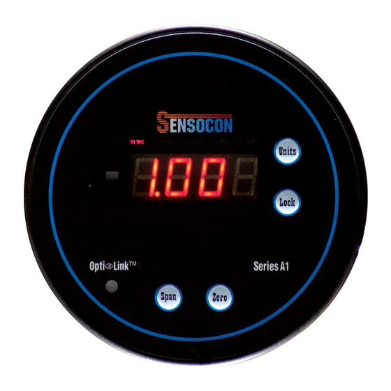
The series A1 and A2 are microprocessor based digital pressure gauges for
positive, negative, and differential measurement designed to be a direct
replacement for mechanical gauges. The ½" LCD display gives the gauge
improved readability and precision. These products also feature 5 user
selectable engineering units including in. w.c., mm w.c., cm w.c., kPa, and
Pa. The A2 series adds a "process arch" which gives the gauge a similar
look to mechanical gauges by giving a continuous percent output status.
1.1 Model Number Configuration
Example
A2100-03
A
Model
1
Display
2
Control
0
0
Transmitter
1
Accuracy
Range
1.2 Specifications
Maximum Pressure: Ranges ≤ 4" w.c. = 2 PSI; Ranges ≥ 5" w.c. = 10 PSI
Media compatibility: Air and compatible non combustible, non corrosive
gasses
Accuracy*: Axxx0-xx - 1.00%; Axxx1-xx - 0.50%
Temperature Ranges:
Compensated: -10° to 140°F (-23° to 60°C)
Operating: -10° to 140°F (-23° to 60°C)
Thermal Effect*: +/- 0.012% FS/°F
Output Signal: 4-20 mA (option)
Loop Resistance: 750 Ω Max (for internally sourced power); 1800 Ω Max
(for externally sourced power of 36 VDC)
Power Supply: Universal 16-265 VAC or VDC
Housing Material: Glass Filled Nylon
Enclosure Rating: Designed to meet NEMA 4X face; with optional cover
entire product is weatherproof
Electrical Connections: screw terminals
Response Time: <100 ms
Display: 4 Digit, red LED, ½" digits
Process Connection: Push on connection for
Agency Approvals: Pending – UL, C-UL, CE
Patents Pending
* Custom calibration including improved accuracy and improved thermal
effect are available.
(863) 248-2800
Installation and Operation
Description
Round Panel Mount
Housing
LED display
LED display & arch
N/A
None
4-20 mA
0
1%
1
0.50%
-
01
0 – 0.50"
-
02
0 – 1"
-
03
0 – 2"
-
04
0 – 3"
-
05
0 – 4"
-
06
0 – 5"
-
07
0 – 8"
-
08
0 – 10"
-
09
0 – 15"
-
10
0 – 20"
-
11
0 – 30"
3
/
" tubing
16
www.sensocon.com
Manual
1.3 Dimensional Drawings
2. INSTALLATION
2.1 Mounting
Flush Mounting – For new applications, cut a 4
Insert the control with the provided gasket through the hole and secure it to
the panel with the provided mounting tabs and screws. Retrofitting old
technology is also easy with the Series A1 and A2. They have been
designed to fit in industry standard holes ranging from 4
simply remove the old device and insert the new control into the existing
cut out.
Surface Mounting – Surface mounting the Series A1 or A2 requires the
optional weather proof cover. Once the control is wired and the weather
proof cover has been attached, the control can be mounted to any flat
surface with the four mounting screws provided with the cover.
Flush Mounting with Weather Proof cover – The Series A1 and A2 can also
be flush mounted with a weather proof cover. The procedure is the same as
above, but utilizes two extra long mounting screws (provided with the
weather proof cover) for the bottom two panel connections.
Flush Mounting
Flush Mounting with Weatherproof Cover
Bulletin 101-0
Series A1 & A2
9
/
" hole in the panel.
16
9
13
/
" to 4
/
" so
16
16
Surface Mounting
1
Advertisement
Table of Contents

Summary of Contents for Sensocon A1 Series
- Page 1 Process Connection: Push on connection for ” tubing Flush Mounting Surface Mounting Agency Approvals: Pending – UL, C-UL, CE Patents Pending * Custom calibration including improved accuracy and improved thermal effect are available. Flush Mounting with Weatherproof Cover (863) 248-2800 www.sensocon.com...
-
Page 2: Limited Warranty
4-20 mA: 5000 VAC to all other inputs and outputs LIMITED WARRANTY 3. OPERATION SENSOCON warrants its products to be free from defects in materials and workmanship for a period of one (1) year from the date of 3.1 Display...
Need help?
Do you have a question about the A1 Series and is the answer not in the manual?
Questions and answers