
Subscribe to Our Youtube Channel
Related Manuals for Delta OHM HD35AP


Summary of Contents for Delta OHM HD35AP
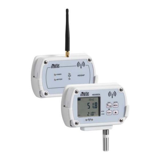
- Page 1 English Operating manual Wireless data logging HD35… series Companies / Brands of GHM www.deltaohm.com Keep for future reference.
-
Page 2: Table Of Contents
ENDING COMMANDS TO THE BASE UNIT FROM A MOBILE PHONE 6.8.2 GPRS/3G TCP/IP C ..............26 ONNECTION HD35AP – HD35AP…G – HD35APS – HD35APW ..28 TECHNICAL FEATURES OF BASE UNITS 6.10 HD35APD ............29 TECHNICAL FEATURES OF BASE UNIT 6.11... - Page 3 8.5.1 ................53 NPUTS CONFIGURATION ....................55 ALIBRATION 8.6.1 ................ 55 SENSOR ALIBRATION 8.6.2 ..............56 EPLACING THE SENSOR 8.6.3 ................ 57 SENSOR CALIBRATION 8.6.4 ..............58 SENSOR UTOCALIBRATION 8.6.5 ..........59 ALIBRATING THE RELATIVE HUMIDITY SENSOR 8.6.6 ............60 IFFERENTIAL PRESSURE CALIBRATION 8.6.7 .......
-
Page 4: Introduction
The correctness of the transmitted data is ensured by the bidirectional communication be- tween the base unit and the remote data loggers. HD35AP-S basic PC software, downloadable free of charge from the Delta OHM website, al- lows configuration of all system devices, display of connection status, level of the RF signal and HD35 V1.12... - Page 5 The data transferred to the PC are entered into a database. Data loggers comply with EN 12830 standard. The optional HD35AP-CFR21 advanced ver- sion of the software is designed in compliance with FDA 21 CFR part 11 recommendations: the operations are protected by access codes and a record of the performed operations is kept.
-
Page 6: System Components
HD35RE… R EPEATERS These devices are able to act as a bridge between the base unit HD35AP… and the remote data loggers HD35ED…, allowing the communication distance between data loggers and base unit to be increased. Several repeaters in cascade can be used. -
Page 7: Installing The System
To check and make the system operational, proceed as follows: 1. Install HD35AP-S and MySQL softwares 2. Connect the battery to the base unit 3. Connect the base unit to the PC 4. - Page 8 ONNECTING BASE UNIT TO YOUR The HD35AP... base unit can be connected to the USB port of a PC through the CP31 cable (directly with USB A-type connector for HD35APD…). In this connection mode, the base unit is powered through the USB port of the PC.
- Page 9 HECK THE CLOCK SETTING Select the item " Setting of date and time " of HD35AP-S software and make sure that the clock of the base unit is updated. If the clock is not updated, set it as explained in the chapter "...
- Page 10 " Adding devices to the network " in the software online help, is briefly outlined hereunder: 1. Select the command " Network " of HD35AP-S software. 2. In the section " Add Devices " of the window " Network ", select the button " Execute search ".
- Page 11 The correct RF communication between base unit and the other devices connected to the net- work can be checked in the following ways: • In the main window of the HD35AP-S software, by checking that the RF signal level re- mains high, that the strength of the received signal RSSI (Received Signal Strength Indi- cation) exceeds -85 dBm and that the percentage of transmission errors PER (Packet Er- ror Rate) is close to zero.
- Page 12 7 only for the repeater. 13. C ONFIGURING NETWORK PARAMETERS Through the HD35AP-S software, set all the system operation parameters: logging intervals, alarm thresholds, user codes, etc. For data loggers, specify whether they are installed in a stationary location or mobile location (for ex.
-
Page 13: Network Modification
" Removing devices from the network " of the software online help, and briefly described here- under: Select the command " Network " of the HD35AP-S software. In the section " Delete Devices " of the window " Network ", select the device that you wish to remove from the network. -
Page 14: Installing The Housing For Indoor Use
5 INSTALLING THE HOUSING FOR INDOOR USE The installation of models in indoor-use housing can be fixed, by means of anodized-aluminum flanges to be attached to the back of the housing, or removable, by means of a practical plas- tic support to be fixed to the wall. The use of flanges allows preventing the instrument to be taken away, thanks to the possibility of applying a padlock, inserted in a fastening pin to be fixed to the wall. -
Page 15: Base Unit Hd35Ap
6 BASE UNIT HD35AP… VAILABLE VERSIONS • HD35AP: With USB output only. • HD35APD: With the USB output only. “Dongle” version powered only by the PC USB port (without internal battery and without input for the external power supply). • HD35APS: With USB output and RS485 output with MODBUS-RTU protocol. -
Page 16: Escription
ESCRIPTION 1. RF antenna for transmission in ISM band. In the HD35APW, HD35APG and HD35AP3G models the antenna is on the left. In the other models the antenna is in the center. 2. POWER LED: in red color, it indicates the presence of an external power supply; it blinks if the battery is recharging. - Page 17 1. RF antenna for transmission in ISM band. 2. POWER LED: in red color, it indicates the presence of an external power supply. 3. Connector for external 8…30 Vdc power supply. 4. RS485 (Modbus-RTU protocol) connector. 5. ETHERNET RJ45 connector. 6.
- Page 18 1. RF antenna for transmission in ISM band. 2. Input for external power supply. 3. Mini-USB connector for PC connection. 4. Housing closing hooks. 5. GSM/3G antenna. Place the GSM/3G antenna at least 30 cm away from the RF antenna. HD35 V1.12...
-
Page 19: Rf Leds Signals
The HD35APW base unit can be connected to a PC through an Ethernet or Wi-Fi local net- work. The choice of the connection mode, Ethernet or Wi-Fi, and of the relevant settings must be performed with the HD35AP-S software. The HD35APR base unit can be connected to a PC through an Ethernet local network In the connection mode through local network, the HD35APW base unit must be powered by means of the SWD06 external power supply. - Page 20 Ethernet cable. Fig. 6.5.1: ETHERNET connection In Wi-Fi mode, connect the base unit to an available Wi-Fi network using the HD35AP-S soft- ware (see software instructions). The base unit connects to the router of the local network (Wi-Fi Access Point, in Wi-Fi mode) and works as a client-type device.
-
Page 21: Rs485 Connection
RS485 CONNECTION The HD35APR and HD35APS base units have a RS485 communication port with MOD- BUS-RTU protocol. For connecting the HD35APS base unit, use the CPM12-8D… series cables with 8-pole M12 connector. The figure and the table below show the numbering and the func- tion of the connector contacts: Other sensors with RS485 output... -
Page 22: Hd35Apr Connections
• Ports = 5100 for proprietary TCP protocol (8 sockets), 502 for Modbus TCP/IP protocol (2 sockets) The ETHERNET settings can be changed with the HD35AP-S software. It is possible to restore the factory parameters by placing the short jumper next to the NET RST push-button between the “2”... -
Page 23: Gsm/3G Connection
6. Reconnect the battery. 7. Close again the housing by fixing the 4 front screws. Through the HD35AP-S software, set the necessary information for GSM/3G operation: SIM PIN, name of the APN access point, e-mail account and addresses, FTP address, telephone numbers, data transmission mode, etc. - Page 24 TAB. 6.7.1: SMS commands Command Description RESET Reset of the base unit EMAIL-ON Activates periodic download of measurement data via e-mail EMAIL-OFF Deactivates periodic download of measurement data via e-mail EMAIL-PERIOD= period index Set the transmission interval via e-mail, where period index: 0->15 min, 1->30 min, 2->1 hour, 3->2 hours, 4->4 hours, 5->8 hours, 6->12 hours, 7->24 hours, 8->2 days, 9->4 days, 10->1 week EMAIL-FORMAT= format index...
- Page 25 HD35AP-S software and if the SMS text starts with a user-defined key word. The key word is set through the HD35AP-S software, going to the menu " GSM options " at the item " SMS re- cipients " and setting the field " SMS keyword " (see chapter " GSM settings " of the software online help).
-
Page 26: Gprs/3G Tcp/Ip C
1) HD35AP…G = Client , PC = Server HD35AP…G acts as TCP client and requests the connection to the PC, the PC acts as TCP server and waits for the connection request. The server IP address (PC or Router) must be public and can be either static or dynamic;... - Page 27 TCP-LISTEN-PORT=2020). 2. Send to HD35AP…G the SMS command TCP-SERVER-ON. 3. HD35AP…G replies with a first SMS to confirm that the command has been accepted. Wait for a second SMS with the confirmation that the TCP server functionality has been activated and with the IP address (and port number) assigned to HD35AP…G.
-
Page 28: Technical Features Of Base Units Hd35Ap - Hd35Ap
HD35AP – HD35AP…G – HD35APS – HD35APW TECHNICAL FEATURES OF BASE UNITS Transmission frequency 868 MHz, 902-928 MHz or 915.9-929.7 MHz (not for HD35APG) according to the model Antenna External whip antenna Transmission range In open field: 300 m (E, J)/ 180 m (U) towards data loggers with internal antenna. -
Page 29: Technical Features Of Base Unit Hd35Apd
6.10 HD35APD TECHNICAL FEATURES OF BASE UNIT Transmission frequency 868 MHz or 902-928 MHz depending on the model (915.9-929.7 MHz not available) Antenna Internal Transmission range In open field: 180 m (E, U) (could be reduced in presence of obstacles or adverse atmospheric conditions) Output USB with A type connector... -
Page 30: Technical Features Of Base Units Hd35Ap
6.12 HD35AP…GMT TECHNICAL FEATURES OF BASE UNITS Power supply 18…27 Vdc Power consumption < 16 mA during measurement < 1 A peak during GSM activity Internal battery 12 V lead-acid rechargeable The battery charger is integrated in the box Transmitting frequency 868 MHz, 902-928 MHz or 915.9-929.7 MHz (not for HD35APGMT) de-... -
Page 31: Hd35Re
7 HD35RE… REPEATERS VAILABLE VERSIONS • HD35RE: In housing for indoor use, with external power supply and rechargeable in- ternal backup battery. • HD35REW: In IP 67 waterproof housing, with internal not rechargeable battery. HD35RE ESCRIPTION OF IN HOUSING FOR INDOOR USE 1. -
Page 32: Description Of Hd35Rew In Waterproof Housing
HD35REW ESCRIPTION OF IN WATERPROOF HOUSING 1. RF Antenna. 2. BATTERY LED: green color, it indicates the internal battery charge level. As the battery is running low, the LED blinks with a lower and lower frequency (the blink period increases of 1 second for each 10% decrease of the battery charge). -
Page 33: Arrangement Of The Repeaters
HD35AP.. base unit, without interposing HD35REW repeaters between the new devices and the base unit;... -
Page 34: Technical Features Of The Repeater Hd35Re
HD35RE ECHNICAL FEATURES OF THE REPEATER Transmission frequency 868 MHz, 902-928 MHz or 915.9-929.7 MHz according to the model Antenna External whip antenna Transmission range In open field: 300 m (E, J)/ 180 m (U) towards data loggers with internal antenna. >... -
Page 35: Echnical Features Of The Repeater
HD35REW ECHNICAL FEATURES OF THE REPEATER Transmission frequency 868 MHz, 902-928 MHz or 915.9-929.7 MHz according to the model Antenna External whip antenna Transmission range In open field: 300 m (E, J)/ 180 m (U) towards data loggers with internal antenna. >... -
Page 36: Hd35Ed
8 HD35ED… DATA LOGGERS FOR INDOOR USE ESCRIPTION Models without LCD display Models with LCD display ALARM LED: red color; it blinks when a measurement is in alarm condition. BATTERY LED: green color, it indicates the internal battery charge level. As the battery is running low, the LED blinks with a lower frequency (the blinking period increases of 1 sec- ond for each 10% decrease of the battery charge). - Page 37 M12 connector M12 connectors IN 1 IN 2 Model Connectable probes Model Connectable probes HD35ED7P/1TC TP35... (Pt100 / Pt1000) HD35ED7P/2TC TP35... (Pt100 / Pt1000) HD35EDN/1TC TP35N... (NTC) HD35EDN/2TC TP35N... (NTC) HD35ED1NTC HP3517TC... / TP35N... (NTC) HP3517TC... IN 1 TP35N... (NTC) HD35ED1N/2TC HD35ED17PTC HP3517ETC...
- Page 38 Differential pressure Ingressi pressione differenziale Fixed vertical inputs (metal inputs with tube clamp RH/T probe ring in HD35ED1N4r5TV) (metal inputs with tube clamp ring in HD35ED1N4r5TV) connector Fixed vertical Photo-radiometric RH/T probe sensor Model Connectable probes HD35ED1N/2TC TP35N... (NTC) HD35ED1NI…TCV LP35PHOT HD35ED14bNI…TCV LP35PHOT...
- Page 39 Data logger models in indoor-use housing In order to highlight the physical quantities measured by data loggers, order codes include some identification characters for the various quantities, according to the following convention: 1 = Humidity 4b = Atmospheric pressure (barometer) 4 = Differential pressure (4r1 = range 1, 4r2 = range 2, etc.) N = Temperature with NTC10K sensor (N/1 = 1 channel, N/2 = 2 channels, N/3 = 3 channels) 7P = Temperature with Pt100/Pt1000 sensor (7P/1 = 1 channel, 7P/2 = 2 channels, 7P/3 = 3 channels)
- Page 40 TAB. 8.1.2: data logger models in indoor-use housing OPTIONAL MEASUREMENTS INPUTS Fig. Conn. Built-in Model sensors Pt100 Patm Custom Graphic ∆P Pt1000 • • HD35ED 7P/1 TC • • HD35ED 7P/2 TC • • HD35ED 7P/3 TC • • HD35ED N/1 TC •...
- Page 41 OPTIONAL MEASUREMENTS INPUTS Fig. Conn. Built-in Model sensors Pt100 Patm Custom Graphic ∆P Pt1000 • • • • HD35ED 1NB Sensor • • • • • HD35ED 1NAB integrated in RH module • • • • • • HD35ED 14bNAB Transmitters with 0÷20 mA, 4÷20 mA, 0÷50 mV or 0÷1 V output 3 terminal •...
-
Page 42: Connection To Wireless Network
ONNECTION TO WIRELESS NETWORK The device can be connected and disconnected from the wireless network by pressing for 5 seconds the connection button on the front panel (see point 6 of paragraph 8.1). If the device is disconnected, by pressing the connection button for 5 seconds the buzzer emits a beep and the green RF LED blinks for one second to indicate the start of the connection pro- cedure. - Page 43 Different measurement units can be set for certain quantities. The setting can be done through the HD35AP-S software (see the software instructions) or by accessing the configuration menu with the front keyboard (see paragraph The menu in LCD data loggers on page 44).
-
Page 44: Maximum, Minimum And Average Of The Measurements
8.3.1 Maximum, minimum and average of the measurements To display the maximum value (MAX), the minimum value (MIN) and the average (AVG) of the acquired values, press the FUNC key until the desired function is shown on the display. Function Indicator Custom LCD Graphic LCD Fig. - Page 45 firm with ENTER. To exit the main menu or a submenu, select the item EXIT (last menu item). Changing a parameter After selecting the desired parameter, it can be changed, if allowed, in the following way: Use / keys to highlight the current setting of the parameter. TEMPERATURE Choose the measuring unit used on display...
- Page 46 5) RF offline: enables or disables the RF stage of the data logger. Activation or deac- tivation of the RF stage can be performed also through the connection button. 6) Exit: returns to the main menu. 4) Ch x settings (x=1, 2, 3) – Only available in the models with configurable inputs 1) Ch x info: lists all the general information of the input channel Ch x of the instru- ment: name of measurement, probe type, resolution.
- Page 47 Upper threshold Hysteresis Hysteresis Lower threshold ALARM ALARM Fig. 8.4.1: hysteresis of the alarm thresholds 7) Alarm time delay 1) Quantity 1 alarm delay: delay for alarm activation of quantity 1. The type of quantity depends on the data logger model. 2) …...
- Page 48 10) Clock 1) Clock Configuration: date/time of data logger. Read-only parameter if the in- strument is connected to a base unit. 2) Exit: returns to the main menu. 11) Password 1) Reset password level: exits menu disabling immediately the password (the password will not remain active for some minutes like it usually happens when exit- ing a menu: you will have to re-enter the password even if you access the menu at once).
-
Page 49: The Menu In Data Loggers With Custom Lcd
8.4.2 The menu in data loggers with custom LCD To access a menu parameter proceed as follows: Press MENU, the first digit of the password will blink. Using / keys, set the first digit and confirm with ENTER, the second digit of the pass- word will blink. - Page 50 (equal to the number of interposed repeaters plus 1). Read-only parameter if the instrument is connected to a base unit. 5) RF_OFF_LINE: enables or disables the RF stage of the data logger. Select NO to activate the RF stage. Activation or deactivation of the RF stage can be done also through the connection button.
- Page 51 6) ALRM_DELY_MENU (delay for alarm activation) 1) Quantity 1_ALRM_DELY: delay for alarm activation of quantity 1. The type of quantity depends on the data logger model. 2) … 3) Quantity n_ALRM_DELY: delay for alarm activation of quantity n. The type of quantity depends on the data logger model.
- Page 52 11) CAL_MENU (calibration) – Only available with administrator password 1) RH_75%_CAL: relative humidity sensor calibration at 75%RH. 2) RH_33%_CAL: relative humidity sensor calibration at 33%RH. 3) HOSE_LEN_m: length (in meters) of the tube connecting the input of the instru- ment to the pressure measuring point (enter the length of only one of the two tubes).
-
Page 53: Connecting The Model With Terminal Header Inputs
8.5.1 I NPUTS CONFIGURATION Configuration of inputs can be implemented through the HD35AP-S software (see software in- structions) or, if the data logger is equipped with a display, through the front keyboard. To configure the input channel ch x (x=1,2,3 is the number of the input) through the keyboard, access the menu and select the item Ch x settings ⇒... - Page 54 The procedure can be stopped at any moment by selecting the option CANCEL and confirming with ENTER. A user name can be associated to each measurement channel to remind the type of physical quantity detected. The user name can be set only through the HD35AP-S software. HD35 V1.12...
-
Page 55: Calibration
LCD, the menu item CAL_MENU ⇒ CAL_TYPE and setting the FACT (factory) option. Calibration can be performed with HD35AP-S software (see software instructions) or, if the data logger has a display, through the front keyboard. 8.6.1 CO SENSOR ALIBRATION This calibration is available in HD35ED[G]14bNAB and HD35ED[G]1NAB models. -
Page 56: Eplacing The Co Sensor
Calibration procedure: Place the instrument in clean air or connect the nitrogen bottle as indicated above. Wait for at least 15 minutes for the measurement to stabilize, with the instrument on. Access the menu with the administrator password and select the item Calibration ⇒... -
Page 57: Co Sensor Calibration
CALIBRATION 1) CO 0 ppm calibration 2) CO sensitivity calib. 3) CO Calibration 4) Calibration Type 5) Exit select <ENTER>confirm Enter the sensitivity value, select the option and confirm with ENTER: the instru- ment stores the value and returns to the calibration submenu. CO SENSITIVITY CALIB. -
Page 58: Co 2 Sensor Autocalibration
The instrument tests the measurement stability. Wait for a few minutes for measurement completion. In the meantime, don’t stay too close to the instrument to avoid altering the measurement. WAIT FOR STABILIZATION OF CO CONCENTRATION… Please stay away to not alter measures Meas. -
Page 59: Calibrating The Relative Humidity Sensor
8.6.5 C ALIBRATING THE RELATIVE HUMIDITY SENSOR The sensor can be calibrated in the two points 75%RH and 33%RH. Before starting the calibra- tion procedure, it’s better to check if a new calibration is necessary, with the aid of 75.4%RH and 33%RH saturated solutions (except HD35ED[G]1…B models, that require a climatic cham- ber): a calibration will be performed only if an error of a few humidity points in one of the two calibration points is detected. -
Page 60: Differential Pressure Calibration
Remove the threaded ring with the probe from the container of the saturated solution and close the container with the solution. To calibrate the second point, repeat the procedure from step 2 to step 7 with the second saturated solution (Note: in the HD35ED...TVI models, for a better accuracy, calibrate the second point at a temperature close to that of the first point). -
Page 61: Echnical Haracteristics Of Data Loggers In Indoor Use Housing
2 years typical for the other models, with logging interval 30 s and measure- with HD35AP...) ment interval 30 s for ∆P ranges r1…r4 models, 10 s for HD35EDH and 5 s for the other models. Operating temperature -20…+70 °C (-10…+70 °C for models with grid) - Page 62 TAB. 8.7.1: memory capacity of data loggers in indoor use housing Number of storable Minimum Model Stored quantities samples (**) logging interval HD35ED 7P/1 TC 68,000 HD35ED 7P/2 TC from 52,000 to 68,000 (***) HD35ED 7P/3 TC from 42,000 to 68,000 (***) HD35ED N/1 TC 68,000...
- Page 63 TAB. 8.7.2: measurement characteristics (instrument in line with sensor) For all data logger models except versions with terminal header inputs Temperature - NTC10K Sensor For …N…TC and …TV versions Sensor NTC 10 kΩ @ 25 °C Measuring range -40…+105 °C Resolution (instrument) 0.1 °C Accuracy...
- Page 64 Atmospheric Pressure Sensor Piezo-resistive Measuring range 300…1100 hPa Resolution (instrument) 0.1 hPa Accuracy ± 0.5 hPa (800...1100 hPa) @ T=25°C ± 1 hPa (300...1100 hPa) @ T=0...50°C Stability 1 hPa/anno Temperature drift ±3 hPa tra -20…+60 °C Differential Pressure range 1...4: Piezoresistive Sensor range 5: Thermal mass flow sensing element Measuring range...
- Page 65 UVB Irradiance Sensor Photodiode Measuring range 0…100 W/m Resolution (instrument) 0.01 W/m (0...10 W/m ), 0.1 W/m (10...100 W/m UVB, peak ≅ 305 nm Spectral range Spectral response See graph 3 Calibration uncertainty <5% (response as cosine law) <6% (linearity) <2% (instrument reading error) ±...
- Page 66 WAVE LENGTH (nm) WAVE LENGTH (nm) Graph 1 – Relative spectral response of Graph 2 – Relative spectral response of illuminance sensor UVA irradiance sensor WAVE LENGTH (nm) WAVE LENGTH (nm) Graph 3 – Relative spectral response of Graph 4 – Relative spectral response of UVB irradiance sensor UVC irradiance sensor HD35...
- Page 67 TAB. 8.7.3: Characteristics of terminal header inputs of HD35EDH instrument: Pt100 / Pt1000 Measuring range -200…+650 °C Resolution 0.1 °C Accuracy ± 0.1 °C (excluding probe error) Sensor coefficient α=0.00385 °C Connection 2, 3 or 4 wires Thermocouple K, J, T, N, E. The inputs are not isolated, use thermocouples with isolated Thermocouple type hot junction.
-
Page 68: Hd35Edw
9 HD35EDW… WATERPROOF DATA LOGGERS ESCRIPTION Models without LCD display Models with LCD display Probes and/or integrated sensors. The aspect of the lower part of the data logger depends on the model (see next paragraph). BATTERY LED: green color, indicates the charge level of the internal battery. As the bat- tery runs low, the LED blinks with a lower and lower frequency (the blink period increases of 1 second for each 10% decrease of the battery charge). - Page 69 IN 2 IN 1 Connector Connectors Model Connectable probes Model Connectable probes HD35EDW7P/1TC TP35... (Pt100 / Pt1000) HD35EDW7P/2TC TP35... (Pt100 / Pt1000) HD35EDWN/1TC TP35N... (NTC) HD35EDWN/2TC TP35N... (NTC) HD35EDW1NTC HP3517TC... / TP35N... (NTC) HP3517TC... IN 1 TP35N... (NTC) HD35EDW1N/2TC HD35EDW17PTC HP3517ETC...
- Page 70 IN 2 IN 1 IN 3 Vertical fixed Connectors RH/T probe Model Connectable probes HD35EDW7P/3TC TP35... (Pt100 / Pt1000) HD35EDWN/3TC TP35N... (NTC) IN 1 TP35878ISS... LP PYRA 02 / LP PYRA 03 HD35EDW1N7PRTC IN 2 LP SILICON-PYRA 04 IN 3 HP3517TC... / TP35N... (NTC) HD35EDWS/3TC HP3510.1 / HP3510.2 IN 1...
- Page 71 Alarm Power supply Cable reset button gland for contact power supply probe alarm output Connector Vertical fixed Connector RH/T probe Model Connectable probes Model Connectable probes HD35EDW1NB…I…TCV LP35PHOT HD35EDWPTC-ALM HD2013 / HD2015 HD35EDW1NB…FTCV LP35PAR IN 1 IN 2 Connector Cable gland Model Connectable probes IN 1...
- Page 72 Data logger models in waterproof housing In order to highlight the physical quantities measured by data loggers, order codes include some identification characters for the various quantities, according to the following convention: 1 = Humidity 4b = Atmospheric Pressure (barometer) N = Temperature with NTC10K sensor (N/1 = 1 channel, N/2 = 2 channels, N/3 = 3 channels) 7P = Temperature with Pt100/Pt1000 sensor (7P/1 = 1 channel, 7P/2 = 2 channels, 7P/3 = 3 channels) K = Temperature with thermocouple sensor (K/4 = 4 channels)
- Page 73 MEASUREMENTS INPUTS Number of Fig. Built-in Model Pt100 Solar PYRA sensors Patm Rainfall WBGT Leaf connectors Pt1000 panel / Lux • • HD35EDW 1 TVI • • HD35EDW 1N TC • • HD35EDW 17P TC • • • HD35EDW 1N TV Sensor integrated •...
-
Page 74: Installation Of Waterproof Housing
NSTALLATION OF WATERPROOF HOUSING The housing for waterproof models can be fixed to a wall or, for outdoor installations, to a 40 mm diameter mast by means of HD2003.77/40 clamping (for housing H=120 mm x L=80 mm). Plastic washers for thermal insulation of the housing from metal parts Fig. -
Page 75: Data Logger With Lcd Option
ATA LOGGER WITH OPTION Through HD35AP-S software, you can select the measurement to be displayed on the main line of the display or set the automatic alternation of measured quantities. Information on the con- nection status, logging (in progress/disabled), and battery charge level are shown. The sec- ondary line displays temperature (if measured by the model). -
Page 76: Connecting The Model Hd35Edwh With Terminal Header Inputs
In all the other configurations, leave the jumper open. Jumper Shunt resistance Fig. 9.5.2: shunt resistance for current input The current input accepts any value in the range 0 to 20 mA. Configuration of inputs is done with the HD35AP-S software (see software instructions). HD35 V1.12... - Page 77 The model HD35ED[L]WH is available in the version with battery supply (connect the battery to the connector shown in Fig. 9.5.3) or in the version for 7...28 Vdc external power supply (connect the external power supply to the terminals shown in Fig. 9.5.4). Battery Connection button...
-
Page 78: Connecting The Model Hd35Edw-Mb With Rs485 Modbus -Rtu Input
HD35EDW-MB RS485 M -RTU ONNECTING THE MODEL WITH ODBUS INPUT HD35ED[L]W-MB model has: • 7…30 Vdc power supply input (terminals 1, 2). • Switched power supply output (terminals 3, 4). It has the same value as the power sup- ply input, but it is active only during the measurement acquisition phase. The out- put can be used to power the sensors. -
Page 79: Dapter For Co Calibration With The Cylinder
DAPTER FOR CALIBRATION WITH THE CYLINDER To calibrate the CO sensor with the aid of the cylinder, unscrew the probe filter, screw the HD31.B3A adapter and connect the cylinder; adjust the bottle flow meter to get a constant flow between 0.3 and 0.5 l/min. Fig. -
Page 80: Wbgt Index Measurement
WBGT INDEX MEASUREMENT HD35EDWWBGT can contemporarily detect the following quantities: Globe thermometer temperature Tg • Natural ventilation wet bulb temperature Tnw • Ambient temperature Ta • On the basis of the detected measurements, the instrument can calculate: WBGT • index: WBGT index in absence of solar irradiation. indoor WBGT = 0.7 Tnw + 0.3 Tg... - Page 81 Warning: don't turn the probe from the vertical direction because the distilled water can exit. The cotton wick calcifies (becomes hard) with time: replace it periodically. Preparation of the TP3204 wet bulb temperature probe: 1. Remove the sensor cap (the cap is not screwed). 2.
- Page 82 Installation on HD32.2.7.1 support: TP3507TC2 dry bulb probe TP3575TC2 or TP3576TC2 globe thermometer TP3204 wet bulb probe Screw for fixing the HD32.2.7.1 support to the tripod HD35.24W flange HD32.2.7.1 support HD35EDWWBGT data logger Installation with HD32.4.17 bracket: TP3204 wet bulb probe TP3575TC2 or TP3576TC2 globe thermometer...
- Page 83 Measurements not according to ISO 7243: The wet bulb temperature probe and the dry bulb temperature probe can be replaced (on re- quest when ordering the data logger) by the HP3517ETC2... combined temperature and relative humidity probe (Pt100 temperature sensor). The WBGT index measurement with combined temperature and relative humidity probe is not according to ISO 7243.
-
Page 84: Technical Characteristics Of Data Loggers In Waterproof Housing
30 s logging interval); (without repeaters, 2 years typical for the other models, with 5 s measurement interval (10 s direct communication for HD35EDW7P/...TC, HD35EDW14bNTC, HD35EDW14b7PTC, with HD35AP...) HD35EDWWBGT) and 30 s logging interval. Operating temperature -20…+70 °C / 0…100 %RH and humidity... - Page 85 TAB. 9.10.1: memory capacity of data loggers in waterproof housing Number of storable Minimum Model Stored quantities samples (**) logging interval HD35EDW 7P/1 TC 68,000 HD35EDW 7P/2 TC from 52,000 to 68,000 (***) HD35EDW 7P/3 TC from 42,000 to 68,000 (***) HD35EDW N/1 TC 68,000...
- Page 86 (**) One sample consists of all the quantities measured and calculated by the data logger at the same instant of acquisition. For example, the model HD35EDW1NTC measures two quantities and calculates five quanti- ties (the derived humidity quantities) and one sample includes one temperature measure and six humidity measurements (the relative humidity measure plus the five derived quantities).
- Page 87 Wet bulb temperature For the model HD35EDWWBGT Sensor Pt100 Measuring range +4…+80 °C Resolution (of the instrument) 0.1 °C Accuracy Class A Stability 0.1 °C/year Probe reservoir capacity 15 cc (TP3501TC2) / 500 cc (TP3204) Probe reservoir autonomy 96 hours @ 50 %RH and 23 °C (TP3501TC2) / 15 days @ 40 °C (TP3204) Dry bulb temperature For the model HD35EDWWBGT Sensor...
- Page 88 Atmospheric pressure Sensor Piezoresistive Measurement range 300…1100 hPa Resolution (of instrument) 0.1 hPa Accuracy ± 0.5 hPa (800...1100 hPa) @ T=25°C ± 1 hPa (300...1100 hPa) @ T=0...50°C Stability 1 hPa/anno Temperature drift ±3 hPa tra -20…+60 °C Solar radiation Sensor Thermopile Measuring range...
- Page 89 Illuminance Sensor Photodiode I: 0…20,000 lux / I2: 0…200,000 lux Measuring range Resolution (instrument) I: 1 lux (0…2,000 lux), 10 lux (>2,000 lux) I2: 10 lux (0…20,000 lux), 100 lux (>20,000 lux) Spectral range In accordance with standard photopic curve V(λ) Spectral response See graph 1 on page 66 α...
- Page 90 TAB. 9.10.3: Characteristics of terminal header inputs of HD35EDWH instrument: Pt100 / Pt1000 Measuring range -200…+650 °C Resolution 0.1 °C Accuracy ± 0.1 °C (excluding probe error) Sensor coefficient α=0.00385 °C Connection 2, 3 or 4 wires Thermocouple K, J, T, N, E. The inputs are not isolated, use thermocouples with isolated Thermocouple type hot junction.
-
Page 91: Hd35Edm
HD35EDM… DATA LOGGERS FOR WEATHER STATIONS 10.1 D ESCRIPTION Five M12 connectors for: • Relative humidity and temperature with NTC sensor combined probe or, alternative- ly, temperature only probe with NTC sensor. • Pyranometer. • Rain gauge. • Cup anemometer. •... -
Page 92: Measuring Probes
If the speed falls below the minimum threshold, the direc- tion indication is frozen at the last value measured, while the speed indication is blocked to the threshold value or to zero (the behaviour is configurable by using the HD35AP-S software). Connector... -
Page 93: Installation Of Housing
10.3 I NSTALLATION OF HOUSING The housing can be fixed to a wall or, for outdoor installations, to a 40 mm diameter mast by means of HD2003.77/40 clamping. Plastic washers for thermal insulation of the housing from metal parts Fig. 10.3.1: installation of housing For outdoor installations, use the optional protection shield against solar radiations. -
Page 94: Display
10.5 D ISPLAY Through HD35AP-S software, you can select the measurement to be displayed on the main line of the display or set the automatic alternation of measured quantities. Information on the con- nection status, logging (in progress/disabled), and battery charge level are shown. The sec- ondary line displays temperature (if measured by the model). -
Page 95: Technical Characteristics Of Data Loggers For Weather Stations
V, 8400 mAh, size C, 2-pole Molex 5264 connector. Battery life 4 years typical (with 10 s measurement interval and 30 s logging interval) (without repeaters, direct communication with HD35AP...) Operating temperature -20…+70 °C / 0…100 %RH and humidity Dimensions... - Page 96 TAB. 10.6.1: Measurement characteristics (instrument in line with sensor) Temperature Sensor NTC 10 kΩ @ 25 °C Measurement range -40…+105 °C Resolution (of instrument) 0.1 °C Accuracy ± 0.3 °C in the range 0…+70 °C / ± 0.4 °C outside Stability 0.1 °C/year Relative Humidity...
- Page 97 Wind speed – Characteristics of the HD54.3 cup anemometer Sensor Passive 3-cup anemometer Measuring range 1…65 m/s Resolution (of the instrument) 0.1 m/s Accuracy ± 0.14 m/s @ 10 m/s installed on a flat terrain site Offset 0.35 m/s Gain 0.765 m s Distance constant 2.55 m @ 5 m/s / 2.56 m @ 10 m/s (ASTM D 5096-02)
-
Page 98: Hd35Ed-Alm Remote Alarm Device
Two bistable relays with potential-free contact are available. In order for relays to be activated in case of an alarm, alarm conditions should be associated to relays activation through the HD35AP-S software (see section Alarm settings in the software instructions). Contacts ar- rangement is shown in the following figure. -
Page 99: Connection To The Wireless Network
11.3 C ONNECTION TO THE WIRELESS NETWORK The device can be connected and disconnected to/from the wireless network by pressing for 5 seconds the connection button on the front panel (see step 6 of paragraph 7.1). If the device is disconnected, by pressing the connection button for 5 seconds the buzzer emits a beep and the green LED activates for one second to indicate the start of the connection pro- cedure. -
Page 100: Modbus
32767. In case of doubt on the registers actually available in a particular model, use the function " Download the list of MODBUS registers of the device " included in the Settings sections of HD35AP-S software (see software instructions). - Page 101 TAB. 12.2: Discrete Inputs – Read-only parameters Address Type Discrete Input description If 1, the device is subjected to RF interference due to the transmission of more covering repeaters. If 1, the last transmitted measurement packet has been lost ...
- Page 102 TAB. 12.4: Input Registers – Read-only parameters Address Type Input Register description Measured values and status of measurement alarms with NTC10K sensor of channel 1 in the set EMPERATURE measurement unit (x10). Alarm for temperature with NTC10K sensor of channel 1: ...
- Page 103 Address Type Input Register description VWC probe output alarm: 0=OFF, 1=lower threshold alarm, 2=higher threshold alarm. with sensor integrated in RH module in the set EMPERATURE measurement unit (x10). Only for models …TVI and …AB. Alarm for temperature with sensor integrated in RH module: ...
- Page 104 Address Type Input Register description Globe thermometer temperature alarm: 0=OFF, 1=lower threshold alarm, 2=higher threshold alarm. WBGT in the set measurement unit (x10). NDOOR INDEX Indoor WBGT index alarm: 0=OFF, 1=lower threshold alarm, 2=higher threshold alarm. WBGT in the set measurement unit (x10).
- Page 105 Address Type Input Register description (VWC) in % (x10) – channel 2. OIL VOLUMETRIC WATER CONTENT Soil volumetric water content alarm – channel 2: 0=OFF, 1=lower threshold alarm, 2=higher threshold alarm. in mV (x10) – channel 2. PROBE OUTPUT VWC probe output alarm –...
- Page 106 Address Type Input Register description 1016 + TC_T sensor of channel N in the set EMPERATURE WITH 200 x (N-1) measurement unit (x10). 1017 + Alarm for temperature with TC_T sensor of channel N: 200 x (N-1) 0=OFF, 1=lower threshold alarm, 2=higher threshold alarm. with TC_N sensor of channel N in the set 1018 + EMPERATURE...
- Page 107 Address Type Input Register description 1046 + Value of quantity associated to channel N if the channel is config- 200 x (N-1) ured as 0…10 V input (HD35EDWH). Alarm for quantity associated to channel N if the channel is con- 1047 + figured as 0…10 V input (HD35EDWH): ...
- Page 108 Address Type Input Register description 6000 + Unit of measurement for with 2-wire Pt100 TEMPERATURE 200 x (N-1) sensor of channel N: 0=°C, 1=°F. 6002 + Unit of measurement for with 3-wire Pt100 TEMPERATURE 200 x (N-1) sensor of channel N: 0=°C, 1=°F. with 4-wire Pt100 6004 + Unit of measurement for...
- Page 109 Address Type Input Register description 10002 Day of last measurement. 10003 Hour of last measurement. 10004 Minutes of last measurement. 10005 Seconds of last measurement. 10006 Packet Error Rate in % of the device (x10). ...
- Page 110 Address Type Holding Register description Lower alarm threshold for with NTC10K sensor of TEMPERATURE channel 2 in the set measurement unit (x10). Higher alarm threshold for temperature with NTC10K sensor of channel 2 in the set measurement unit (x10). Lower alarm threshold for in W/m ...
- Page 111 Address Type Holding Register description Higher alarm threshold for wind chill in the set measurement unit (x10). lower alarm threshold for ranges r1 and IFFERENTIAL PRESSURE r2 in the set measurement unit (the multiplier depends on the set unit). Differential pressure higher alarm threshold for ranges r1 and r2 in the set measurement unit (the multiplier depends on the set ...
- Page 112 Address Type Holding Register description (HD52.3D anemometer) lower alarm threshold in IND SPEED m/s (x100). Wind speed (HD52.3D anemometer) higher alarm threshold in m/s (x100). (HD52.3D anemometer) lower alarm threshold IND DIRECTION in degrees (x10). Wind direction (HD52.3D anemometer) higher alarm threshold ...
- Page 113 Address Type Holding Register description Measurement alarm thresholds for configurable inputs 1000 + Lower alarm threshold for with 2-wire Pt100 TEMPERATURE 200 x (N-1) sensor of channel N in the set measurement unit (x10). 1001 + Higher alarm threshold for temperature with 2-wire Pt100 sen- ...
- Page 114 Address Type Holding Register description 1034 + Channel N lower alarm threshold in %. Only if channel N is 200 x (N-1) configured as potentiometric input (HD35EDH). 1035 + Channel N higher alarm threshold in %. Only if channel N is ...
- Page 115 Address Type Holding Register description 10025 Current second Measurement interval: 0=1s, 1=2s, 2=5s, 3=10s, 4=15s, 5=30s, 10026 6=1min, 7=2min, 8=5min, 9=10min, 10=15min, 11=30min, 12=1h Logging/RF interval: 0=1s, 1=2s, 2=5s, 3=10s, 4=15s, 5=30s, 10027 6=1min, 7=2min, 8=5min, 9=10min, 10=15min, 11=30min, 12=1h Network RF channel.
- Page 116 Address Type Holding Register description Relay #1 deactivation duration in seconds (1…54000 s) in case 10059 of cyclical activation (Coils – address 18 = 0). Number of relay #1 activations in case of cyclical activation 10060 (Coils – address 18 = 0). Relay #2 activation duration in seconds (1…54000 s) in case of ...
-
Page 117: Dimensions
13 DIMENSIONS The following figures show the dimensions of the instruments in mm. HD35AP - HD35APW - HD35APG - HD35RE HD35APS HD35ED… versions with fixed RH/T probe HD35ED… versions with grid HD35ED… versions with M12 connectors HD35ED… versions with terminals HD35 V1.12... - Page 118 HD35ED… versions with Support for removable installation differential pressure inputs Flanges for fixed installation Lock pin HD35APR HD35 V1.12...
- Page 119 HD35REW HD35EDW… versions with M12 connectors HD35EDW… versions with fixed RH/T probe HD35EDW… versions with terminal header HD35EDW… versions with CO probe HD35 V1.12...
- Page 120 HD35EDLM…TC HD35 V1.12...
-
Page 121: Relative Humidity And Temperature Probes
14 RELATIVE HUMIDITY AND TEMPERATURE PROBES Combined probes for temperature and relative humidity: HP3517… R.H. Sensor Capacitive Temperature sensor NTC 10 kΩ @ 25 °C (HP3517TC…) Pt100 1/3 DIN (HP3517ETC…) R.H. sensor measurement range 0…100 %RH Temperature sensor measurement -40…+105 °C (HP3517TC… with NTC 10 kΩ sensor) range -40…+150 °C (HP3517ETC…... - Page 122 TP35.4… Sensor 4-wire Pt100 Temperature range -50…+105 °C Accuracy 1/3 DIN Cable length 3, 5 or 10 m standard, other lengths on request Free wires or 4-pole M12 female connector (option /C) Connection Material AISI 316 stainless steel tube TP35.5… Sensor 3-wire Pt1000 Temperature range...
- Page 123 TP35878ISS… Sensor 4-wire Pt100 Temperature range -40…+85 °C Accuracy 1/3 DIN Cable length 5 or 10 m standard, other lengths on request Connection 4-pole M12 female connector TP35.5AF.5… Sensor 4-wire Pt100 Temperature range -110…+180 °C Accuracy Class A Cable length 5 m standard, other lengths on request Shield: Inox + PTFE Free wires or 4-pole M12 female connector (option /C)
- Page 124 Temperature probes with sensor NTC 10KΩ @ 25 °C TP35N1... Sensor NTC 10 kΩ @ 25 °C Temperature range -20…+75 °C Accuracy ± 0.3 °C in the range 0…+70 °C / ± 0.4 °C outside Cable length 3, 5 o 10 m standard, other lengths on request Connection Free wires or 4-pole M12 female connector (option /C) Material...
- Page 125 TP35N6... Sensor NTC 10 kΩ @ 25 °C Temperature range -20…+70 °C Accuracy ± 0.3 °C in the range 0…+70 °C / ± 0.4 °C outside Cable length 5, 10, 15 or 20 m standard, other lengths on request Connection 4-pole M12 female connector Material Plastic body, aluminum flange...
- Page 126 Connections of Pt100, Pt1000 and NTC 10KΩ temperature probes with M12 connector: Reference External view of the instrument M12 connector Probe M12 connector Pt100 NTC 10KΩ Pt1000 2 wires Pt100 Pt100 Pt1000 Pt1000 4 wires 3 wires HD35 V1.12...
-
Page 127: Storage Of Instruments
15 STORAGE OF INSTRUMENTS Instruments storage conditions: • Temperature: -40...+70 °C. • Humidity: less than 90 %RH no condensation. • In storage, avoid places where: humidity is high; • • instruments are exposed to direct sun radiation; instruments are exposed to a high temperature source; •... -
Page 128: Ordering Codes
SWD06 (optional, not for HD35APD, HD35APR, HD35APGMT and HD35AP3GMT) or solar panel (only HD35APGMT and HD35AP3GMT). It includes HD35AP-S basic software downloadable from Delta OHM web site. The unit is supplied with: HD35-BAT1 lithium-ion (not for HD35APD, HD35APR, HD35APGMT and HD35AP3GMT) or 12 V lead-acid (only... - Page 129 EPEATERS HD35RE RF signal repeater. Housing for indoor. Power supply through PC USB port or ex- ternal power supply unit SWD06 (option). Supplied with: internal lithium-ion rechargeable battery HD35-BAT1, wall support HD35.03, instruction manual. Radio frequency (868, 902-928 or 915.9-929.7 MHz) should be speci- fied upon ordering.
-
Page 130: Carbon Dioxide (Co
ATA LOGGER HD35ED… Wireless data logger. Stores measurements in the internal memory. Transmits the acquired data to the base unit automatically at regular intervals or on re- quest. Optional LCD Display. Acoustic alarm with internal buzzer. Power supply through non-rechargeable lithium-thionyl-chloride (Li-SOCl ) 3.6V inter- nal battery. - Page 131 ROBES TEMPERATURE AND RELATIVE HUMIDITY COMBINED PROBES HP3517… Temperature and relative humidity combined probe. R.H. sensor measure- ment range: 0…100%. Temperature sensor: NTC10KΩ for HP3517TC…, Pt100 for HP3517ETC. NTC10KΩ sensor measurement range: -40…+105 °C. Pt100 sensor measurement range: -40…+150 °C. R.H. sensor operating tempera- ture: -20…+80 °C standard, -40…+150 °C with option E.
- Page 132 TP472I… Stainless steel temperature probe. 4-wire wire wound Pt100 sensor. Stem di- mensions: Ø 3 x 300 mm. Cable length: 2 m. Cable termination: open wires (TP472I/W) or 4-pole M12 female connector (TP472I/C). Operating tempera- ture: -196…+500 °C. TP35878ISS… 1/3 DIN Pt100 contact temperature probe for solar panel. Dimensions: Ø 30 mm.
- Page 133 THERMOCOUPLE TEMPERATURE PROBES TP35K6.5 Stainless steel temperature probe. K-type thermocouple sensor wih isolated junction. Cable length 5 m. Cable ending with ree wires. WBGT ROBES FOR MEASUREMENT TP3501TC2 Natural ventilation wet bulb probe. Pt100 sensor. Probe stem probe: Ø 14 mm, length 110 mm.
- Page 134 LP 35 PAR Radiometric probe for measuring photons flow in the field of photosynthesis of chlorophyll (PAR). Cosine correction. Measuring range 0...5000 µmol m Cable length 5 m. M12 connector. LP BL Base with level. On request, to be assembled to the probe upon ordering.
- Page 135 HD2015.5K.1 Kit of accessories for the installation of the HD2015 rain gauge raised 1 m off the ground. HD2003.75 Base for 40 mm diameter mast, with tip to be driven into the ground. HD2003.78 Base for 40 mm diameter mast, to be fixed to the floor. IND SPEED AND DIRECTION SENSORS HD54.3 Passive cup anemometer.
- Page 136 EAF WETNESS SENSORS HP3501.5 Leaf wetness sensor with double sensitive surface. IP 67 protection degree. 5 m cable ending with M12 connector. HP3501.10 Leaf wetness sensor with double sensitive surface. IP 67 protection degree. 10 m cable ending with M12 connector. OIL VOLUMETRIC WATER CONTENT SENSORS HP3510.1.5 2-electrode probe for measuring the soil volumetric water content.
- Page 137 For Windows operating systems. HD35AP-CFR21 Advanced version of the HD35AP-S software including, in addition to the features of the basic software, the management of the data logging system in accordance with the FDA 21 CFR part 11 recommendations.
- Page 138 Only for the models HD35EDW... in waterproof housing. DELTA OHM metrology laboratories LAT N° 124 are accredited ISO/IEC 17025 by ACCREDIA for Temperature, Humidity, Pressure, Photometry / Radiometry, Acoustics and Air Velocity. They can supply calibration certificates for the accredited quantities.
- Page 139 Approvals Sub-GHz certifications: Models HD35….U contain transmitter module FCC ID: X7J-A10040601 IC ID: 8975A-A10040601 Models HD35….J (except HD35AP3G.J) contain TELEC certified RF module: [R] 010-100130 Model HD35AP3G.J contains TELEC certified RF module: [R] 006-000411 IEEE 802.11 (Wi-Fi) certifications: Models HD35APW.E and HD35APW.U contain IEEE 802.11b/g/n module FCC ID: XM5-SMG2SMT IC ID: 8516A-SMG2SMT Model HD35APW.J contains IEEE 802.11b/g/n module FCC ID: XM5-SMG2N2 IC ID: 8516A- SMG2N2...
- Page 140 FCC and IC notices Notice: This device complies with Part 15 -15.247(a2) and 15.247(b) and 15.249 of the FCC Rules and with Industry Canada (IC) licence-exempt RSS standard(s). Operation is subject to the following two conditions: (1) this device may not cause harmful interference, and (2) this device must accept any interference received, including interference that may cause undesired operation.
- Page 141 NOTES...
- Page 142 NOTES...
- Page 143 NOTES...
- Page 144 All DELTA OHM instruments are subject to accurate testing, and are guaranteed for 24 months from the date of purchase. DELTA OHM will repair or replace free of charge the parts that, within the warranty period, shall be deemed non efficient according to its own judgement. Complete replacement is excluded and no damage claims are accepted.
- Page 145 GHM GROUP – Delta OHM | Delta Ohm S.r.l. a socio unico Via Marconi 5 | 35030 Caselle di Selvazzano | Padova | ITALY Phone +39 049 8977150 | Fax +39 049 635596 www.deltaohm.com | info@deltaohm.com The quality level of our instruments is the result of the constant development of the product. This may produce some differences between the information written in this manual and the instrument you have purchased.
- Page 146 GHM GROUP – Delta OHM | Delta Ohm S.r.l. a socio unico Via Marconi 5 | 35030 Caselle di Selvazzano | Padova | ITALY Phone +39 049 8977150 | Fax +39 049 635596 www.deltaohm.com | info@deltaohm.com V1.12 10/01/2018...
Need help?
Do you have a question about the HD35AP and is the answer not in the manual?
Questions and answers