Table of Contents
Advertisement
Quick Links
TITLE
SAFETY INFORMATION..............................1
FEATURES................................................2
1.SPECIFICATIONS....................................2
1-1 General information...........................2
1-2 Electrical Specifications................ .....5
2.PARTS & CONTROLS..............................8
2-1 Name of Parts and Positions.... ..........8
2-2 Operating Instruction....................... 11
2-2-1 Scale Ranging.......................... .. 11
2-2-2 DC Voltage Measurement............... 11
2-2-3 AC Voltage Measurement...............12
2-2-4 AC/DC Current Measurement......... 13
2-2-5 Diode Test.................................. 14
2-2-6 Resistance Measurement.............. 15
2-2-7 Continuity Measurement................ 15
2-2-8 Frequency Measurement........... ....16
3.BATTERY & FUSE REPLACEMENT......... 17
3-1 Battery Check & Replacement............ 17
3-2 FUSE Replacement.......................... 17
4.MAINTENANCE..................................... 19
CONTENTS
PAGE
Advertisement
Table of Contents

Summary of Contents for Center 110
-
Page 1: Table Of Contents
CONTENTS TITLE PAGE SAFETY INFORMATION……..……………...….1 FEATURES………………………………..……..2 1.SPECIFICATIONS………………………..…….2 1-1 General information…………………...…2 1-2 Electrical Specifications……………. ..…5 2.PARTS & CONTROLS……….………….…….8 2-1 Name of Parts and Positions…. ……….8 2-2 Operating Instruction………………….. 11 2-2-1 Scale Ranging…….………………. .. 11 2-2-2 DC Voltage Measurement..……..….. 11 2-2-3 AC Voltage Measurement..……..…..12 2-2-4 AC/DC Current Measurement..….…... -
Page 2: Safety Information
Read First: Safety Information ․ Never use the meter if the meter or test leads look damaged. ․ Be sure the test leads and switch are in the correct position for the desired measurement. ․ Never measure resistance or testing acoustic continuity in a circuit when power is applied. - Page 3 Display: Digital: 4000 counts Analog: 42 segments Maintenance & Clearing: Repairs or servicing not covered in this manual should only by qualified personal. Periodically wipe the case with a dry cloth and detergent . Do not use abrasives or solvents on this instruments. Display Symbol Definition: Low Battery Relative Reading Data Hold...
-
Page 4: Electrical Specifications
Weight: Approx.220g(7.76oz) Dimensions(L×W×H): 150mm×72mm×35mm (5.9”×2.83”×1.38” ) Accessories: Test leads, Spare fuse ( 0.5A/250V ),Batteries and Instruction manual. 1-2 Electrical Specifications Accurace specification:±([… %of reading]+ […number of least significant digits]) at 18℃to 28℃( 64℉to 82℉)≦80%RH Diode Tester Overload Range Resolution Accuracy Test Current Test Voltage protection 1%+ 2... - Page 5 600V 1%+4 1.2%+4 750Vrms 10M Ω DC Current (uA,mA,Auto Range) Burden Range Resolution Accuracy Overload Protection Voltage 400uA 0.1uA 1%+2 <0.25V 0.5A / 250V Fast Blow Fuse 4000uA 1%+2 <1V 0.5A / 250V Fast Blow Fuse 40mA 10uA 1%+2 <0.25V 0.5A / 250V Fast Blow Fuse 400mA 100uA...
-
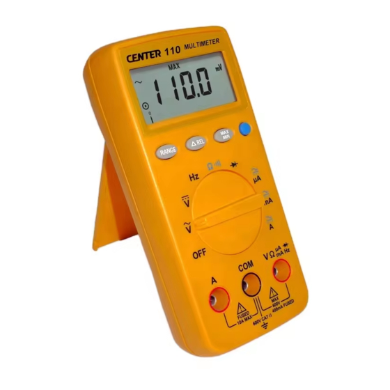
Page 6: Parts & Controls
2.PARTS & CONTROLS 2-1 Name of Parts and Position: IEC 1010 600V CAT II POLLUTION DEGREE 2 WARNING F 0.5A 250V F 10A 250V mA Hz ← LCD Display: Measured values, unit, function and decimal points symbols are displayed. ↑ Relative Button: Press button to enter the relative mode. - Page 7 value is displayed. ․If the meter is in the highest range, the next range is change to the lowest range. To exit the Manual Range mode and return to Auto Range mode, Press and hold down for 1 seconds, the AUTO annunciate turns back on.
-
Page 8: Operating Instruction
∝ Tilt stand 2-2 Operating Instruction 2-2-1 Ranging The meter defaults to autorange mode when you turn on the Meter. Manual ranging is available in V~, V , ohms , A~ , A frequency. To return to autorange, press for 1 second or turn the rotary switch. -
Page 9: Ac/Dc Current Measurement
2-2-4 AC/DC Current Measurements WARNING! To avoid injury, do not attempt a current measurement if the open circuit voltage exceeds the rate voltage of the meter. ⊇ Connect red test lead to the “mA / uA ”jack for Current measurements up to 400mA.( For measuring Current between 400mA to 10A , Connect red test lead to “... -
Page 10: Resistance Measurement
⊂ Connect the red test lead to the anode side and black test lead to the cathode side of the diode being tested. ⊆ Read forward Voltage( V f ) value on LCD. ∈ If the polarity of test leads are reversed with diode polarity ⊂, the digital reading show “... -
Page 11: Frequency Measurement
⊂ Remove power from the circuit being tested and discharge all capacitors. ⊆ Connect test lead to the circuit being measured. ∈ When the impedance between the test jack is lower than 40Ω,it will activate a continuous beeper ( 2KHz). Note: Continuity Test is available to check open/short of the circuit . -
Page 12: Battery Check & Replacement
3-1 Battery Check & Replacement 1. As battery power is not sufficient, LCD will display “ ”. Replacement of two new batteries type AAA 1.5V is Required. 2. Set Range Switch to “ OFF ” position .Use a screwdriver to remove the rear cover. -
Page 13: Maintenance
4.MAINTENANCE WARNING! To avoid electric shock, remove the test leads before opening the case, and close the case before using the meter. To prevent fire and possible arc-flash, use fuses with ratings shown on the back of the meter. Caution! To avoid contamination or static damage, do not touch the circuit board without proper static protection.
Need help?
Do you have a question about the 110 and is the answer not in the manual?
Questions and answers