Table of Contents
Advertisement
Advertisement
Table of Contents

Subscribe to Our Youtube Channel
Related Manuals for Essilor e-Tess

Summary of Contents for Essilor e-Tess
- Page 1 ESSILOR e-Tess User’s guide IMETESSE. V3...
- Page 2 Essilor E-Tess Tracer Congratulations! You have just acquired a high precision Essilor tracer. We strongly recommend that you read this entire manual before using your Essilor tracer, in order to obtain the greatest satisfaction. IMPORTANT The information in this document is non-contractual and provided as a guide.
-
Page 3: Table Of Contents
Configure the connection and the communication parameters _________________________ 15 CHECK PRO_________________________________________________________ 17 3.1. Installation ____________________________________________________________ 17 3.2. Use __________________________________________________________________ 19 USING THE e-TESS TRACER ___________________________________________ 26 4.1. Description of the tracer _________________________________________________ 26 4.2. Initialisation ___________________________________________________________ 26 4.3. Frame tracing __________________________________________________________ 28... - Page 4 Essilor E-Tess Tracer...
- Page 5 In order to reduce the risks associated with the use of electrical equipment - fire, electric shock, injury, etc., it is essential to comply with the basic safety rules. We therefore strongly recommend that you read this manual before switching on your Essilor e-Tess tracer and that you keep it in a safe place for future reference.
-
Page 6: Precautions Required
1.1. ORK SURFACE In order to take full advantage from the high precision of your Essilor e-Tess tracer, we recommend that it is placed on a flat stable surface, free from shocks and vibrations. Your Essilor e-Tess tracer can be positioned up to 5 metres from your PC and/or your edger. -
Page 7: Symbols
Clean the tracer regularly (except the feeler) with a soft cloth dampened with water or neutral detergent (e.g. washing-up liquid). N.B. To prevent the accumulation of dust which could affect the precision of your e-Tess tracer, we recommend closing the protective cover after use. -
Page 8: Installation
Automatic measurement of the frame bridge, binocular tracing. Frame thickness measurement. Differential tightening of the grips. RS232 and RJ45 ports. Memory update by Essilor external USB stick. Internal memory: 1000 Jobs. 5.7" touch screen. Tracer inclination 0° or 10° . -
Page 9: Connections
Not used PC - Ethernet Connector (2) Depending on your configuration, your Essilor e-Tess tracer can be connected to either a PC or an Essilor Delta T edger. Connection to a PC 1. Connect the RS232C cable to the tracer socket (5) and to an RS232C serial port on the PC. (see above figure), Connect the RJ45 cable to the tracer socket (2) and to the Ethernet RJ45 port on the PC. -
Page 10: First Time Use
Essilor E-Tess Tracer N.B. A crossed cable is used. Make sure to respect the connection direction shown on the cable labels corresponding to the symbols used on the edger and the tracer. 2. Make sure that the tracer on/off switch is on the "0" position, 3. -
Page 11: Navigation Principle
Essilor E-Tess Tracer Navigation principle Menu bar Display zone Choice cascade Action bar Main icons Standard tracing Start cycle. "Precal" tracing Stop cycle. Very high curve tracing. Validate, move to next step. Shape alteration. Cancel, return to previous step. Dissymmetric binocular tracing. -
Page 12: Customising The Display
Essilor E-Tess Tracer 2.4. USTOMISING THE DISPLAY Your e-Tess tracer allows you to customise the display of the default trace parameters. Irrespective of the configuration chosen here, each item can still be modified before each tracing job. 1. Press to enter the customisation menu, 2. - Page 13 Essilor E-Tess Tracer 4. Choose the default tracing side (dissymmetric binocular, right eye/left eye monocular, symmetric binocular), by clicking on the corresponding icon, 5. Validate your choice or return to the previous screen 6. Select the dimensions you want to display in the trace screen (maximum 4), from: A, B, D, E, P, 7.
-
Page 14: Configuring The Tracer
Essilor E-Tess Tracer 9. Save your configuration or return to the previous screen 2.5. ONFIGURING THE TRACER 1. Press to enter the product configuration menu, 2. Click on to access tracer configuration. On this screen, you can: 3- Check Pro... -
Page 15: Choose The Language
N.B. Modifying this configuration could have an adverse effect on the operation of your instruments. The configuration in this menu should only be modified if your configuration is not compatible with that proposed by default, with support from your Essilor technician. a. Edger connection... - Page 16 Essilor E-Tess Tracer Port type used, choose by pressing repeatedly: Serial port Ethernet port No PC Communication protocol, choose by pressing repeatedly: OMA (serial port and Ethernet), OMA+ (serial port only), used for the connection with Check Pro, (see Chapter 3),...
-
Page 17: Check Pro
NSTALLATION Check Pro is compatible with the following operating systems: Windows 98, 2000, XP, Millenium. 1. Insert the CD-ROM supplied with your e-Tess tracer. The following window is displayed: 2. Click on "CheckPro" then "OK": the installation procedure starts, 3- Check Pro... - Page 18 Essilor E-Tess Tracer 3. Click on "Next >" and follow the installation steps up to the next screen: 4. Close this window, the application starts automatically. 3- Check Pro...
-
Page 19: Use
Click on the icon on your PC desktop, the application starts: From this screen, all functions can be accessed using icons. N.B. So that Check Pro can communicate with your e-Tess tracer, remember to configure them together (see Chapter 2.3.). - Page 20 Essilor E-Tess Tracer : Partial statistics : Total statistics Each line indicates a dedicated function of your tracer. 2. To exit the screen and return to the previous screen, click on Error messages 1. Click on: List of "optician" errors saved.
- Page 21 1. Click on: 2. In the "Language" tab, choose the application operating language, 3. In the "Port" tab, configure the connection between your e-Tess tracer and your PC (see Chapter 2.3.), 4. Click on "OK" to save your parameters and return to the previous screen, or click on "Cancel" to return to the previous screen (without changing the parameters).
- Page 22 Essilor E-Tess Tracer 4. After a few seconds, the information is displayed on screen, 5. To exit the screen and return to the previous screen, click on Self-test 1. Click on: Jaw test Feeler restitutor test Rotation test Carriage transfer test Feeler transfer test 2.
- Page 23 3. Choose the number of the frame "standard gauge" displayed, corresponding to the gauge to be used, 4. Position the frame "standard gauge" in e-Tess, stable on the four lower studs, with the "V" open upwards, 5. Click on...
- Page 24 2. Choose the numbers of the "frame" and "pattern" standard gauges displayed, corresponding to the standard gauges used, 3. Position the frame "gauge" in the e-Tess tracer, stable on the four lower studs, with the "V" open upwards, 4. Click on to validate, : is displayed in the Check Pro window.
- Page 25 Essilor E-Tess Tracer : The calibration is not OK, a window displays the error message code, Refer to Chapter 7 to find the cause of the problem, √ Then click on to exit the Check Pro screen and press to validate the code on your tracer.
-
Page 26: Using The E-Tess Tracer
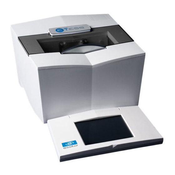
Essilor E-Tess Tracer 3. USING THE e-TESS TRACER 3.1. ESCRIPTION OF THE TRACER Protective cover Clamps Feeler. Tracing chamber Touch screen Supprimé : <sp><sp><sp> <sp><sp><sp>¶ <sp><sp><sp><sp><sp><sp> ¶ 3.2. NITIALISATION 1. Power up the tracer with on/off switch, 2. Wait during the initialisation phase (automatic tests of the tracer functions), The graphic bar indicates the progress of the initialisation phase. - Page 27 If you want to assign a job number: Click on the job number zone, A calculator is displayed to enter the required number between 1 and 9999. By default, the first number available in the list is proposed. 4- Using the e-Tess tracer...
-
Page 28: Frame Tracing
: very high curve tracing (see special cycles below), : "precal" tracing (see special cycles below), 4. Select your tracing side in the following cascade : dissymmetric binocular tracing, : right eye monocular tracing, : left eye monocular tracing, : symmetric binocular tracing, 4- Using the e-Tess tracer... -
Page 29: Special Cycles
2. "Very high curve" frame tracing Thanks to its advanced technology, your e-Tess tracer can trace high curve frames on a standard cycle. This special cycle allows you to trace frames with very high curve for which binocular tracing can only be carried out in monocular mode. - Page 30 4.1. Position your pattern on the pattern holder between the adapter and the magnet. Press the top part of the holder to separate the jaws of the adapter holder and simplify handling. -2- Adapter insertion 4- Using the e-Tess tracer...
- Page 31 4.4. Choose your tracing side, 4.5. Start the cycle 4.6. Your e-Tess tracer automatically detects that it is a pattern trace. If no tracing side has been selected, it will prompt you to select the tracing eye, 4.7. After tracing, enter the nose value on the numeric keypad, then validate 5.
-
Page 32: Recalling A Job
Essilor E-Tess Tracer 3.4. ECALLING A JOB Your e-Tess can store up to 1,000 jobs using numeric references between 1 and 1000. 1. Press to access the library: Preview Job list 2. Use the scroll bar to move through the list and find the required job. After clicking on the line to select it, a preview of the shape is displayed on the right of the screen. -
Page 33: Shape Alteration
Select the dimension you want to modify, B: B-dimension. A-dimension. Upper ½ B-dimension. Right ½ A-dimension. Lower ½ B-dimension. Left ½ A-dimension. Scaling. Use keys C and D to increase or decrease the chosen dimension. 4- Using the e-Tess tracer... - Page 34 4. When your alteration is finished, you can: Save the shape permanently: The shape will be saved with a new job number. Click on key E. A window displays a job number, available in the list: 4- Using the e-Tess tracer...
- Page 35 Save the shape temporarily: The alteration will only be effective for the current processing. Click on key G to return to the dimension screen and continue your job processing. 4- Using the e-Tess tracer...
-
Page 36: Automaintenance
Essilor E-Tess Tracer 4. AUTOMAINTENANCE The functions described in this menu will allow you to troubleshoot any problems you may encounter when using your tracer or help the technician to solve the problem. All of these functions are accessible from the configuration/maintenance screen... - Page 37 Essilor E-Tess Tracer 5. Start the tracing cycle 6. After tracing, the clamps open and an audible signal indicates the end of the calculations: If the check is OK, the screen displays: Press and continue using your tracer. If the check is not OK, the display indicates: Press and perform a complete calibration (see Chapter 5.2.).
-
Page 38: Calibration
Essilor E-Tess Tracer 4.2. ALIBRATION Calibration must be carried out regularly to guarantee High Precision acquisitions, especially when the calibration check is NOK (see Chapter 5.1.). This step may take a certain amount of type and block the use of your tracer, but it is essential to maintain high performance. -
Page 39: Self-Tests
Essilor E-Tess Tracer 11. After tracing, the screen displays: 12. Select the number of the standard gauge in the selection list, 13. Position your corresponding frame "standard gauge" in the tracing chamber, stable on the four lower studs, with the "V" open upwards (for positioning, see Chapter 5.1.), 14. - Page 40 Essilor E-Tess Tracer 2. Select the "Self-tests" function All tests T1 + T2 + T3 + T4 + T5 Jaw test Feeler restitutor test Rotation test Carriage transfer test Feeler transfer test 3. Select the tests you want to perform, 4.
-
Page 41: Statistics
Essilor E-Tess Tracer Press and contact your After-Sales technician. 4.4. TATISTICS This function enables you to display statistics on the use of your tracer. 1. Press to access the configuration/maintenance menu. 2. Select the "Statistics" function : Partial statistics (since servicing by your technician). -
Page 42: List Of Errors
Essilor E-Tess Tracer Nbr of High Precision Nbr of pattern cycles (metal) tracings Nbr of calibrations Nbr of "Precal" cycles Nbr of calibration checks 4. At the end of your consultation, click to go back to the general configuration menu. -
Page 43: Touch Screen Calibration
Essilor E-Tess Tracer : Partial list (since servicing by your technician). : Total list (since you first started using your tracer). 16000 1000 10000 4006 3. At the end of your consultation, click to go back to the general configuration menu. - Page 44 Essilor E-Tess Tracer 2. Select the "Touch screen calibration" function 3. Four crosses will successively appear at the four corners of the screen. Click at the centre of each cross when they appear on screen. Once this operation has been carried out, you get back to the general configuration menu.
-
Page 45: Import-Export
5. Depending on the files requested by your Essilor technician (calibration data or error list), select the corresponding box, then validate 6. When the export is finished, e-Tess is ready for a job, the information has been copied onto the stick which can now be removed. -
Page 46: Adding A Standard
4. Select the "Import-Export" function 5. Select the import pattern, then validate 6. When the import is finished, e-Tess is ready for a job, your new standard will be available for your calibration operations (see Chapters 5.1. and 5.2). If an error occurred during the operation, refer to Chapter 7. - Page 47 3. In the start menu, click on My PC, your stick must be displayed: "removable disk", 4. Double-click on this disk, 5. Copy the file in format .tar.gz sent by your Essilor retailer to the root directory of your stick, 6. Close this disk, 7.
-
Page 48: Error Codes
Essilor E-Tess Tracer 6. ERROR CODES The actions required if an error occurs are indicated below. If one of these codes appears repeatedly or remains after the actions proposed below, record this code and contact your technician. Opt1 Contact your technician with the machine data. - Page 50 Essilor Instruments USA 8600 W. Catalpa Avenue, Suite 703 Chicago, IL 60656 Phone: 855.393.4647 Email: info@essilorinstrumentsusa.com www.essilorinstrumentsusa.com...
Need help?
Do you have a question about the e-Tess and is the answer not in the manual?
Questions and answers