Table of Contents
Advertisement
Quick Links
z Capable of connecting two optional wired RAM4 or one wired RAM4 and up to four Wireless
RAM4W remote access microphones using SCU-31 wireless access point
z Integrated NMEA 2000 interface supporting all PGNs for Navigation, GPS, AIS and DSC functions
z Integrated Dual Channel AIS (Automatic Identification System) receiver
z GPS Compass, Waypoint and GPS status pages
z Dual Zone 25W PA / Loud Hailer with preprogrammed horn, siren, fog signals and listen back
z Submersible IPX8 (5 feet or 1.5 meters for 30 minutes)
z Integrated 32 Code Voice Scrambler and 4 Code Voice Scrambler
z AIS / AIS SART target display: MMSI, Call Sign, Ship Name, BRG, DST, SOG and COG
z Front panel microphone can be connected to rear panel and extended 20 feet using MEK-4
mic extension kit
z Programmable CPA or TCPA collision avoidance alarms
z Advanced 80 dB commercial Grade Receiver with Local / Distance Attenuator
z Intercom feature allows you to communicate between the radio, RAM4 and Wireless RAM4W
microphones
z Integrated Voice Recorder to play back up to two minutes of RX receive audio
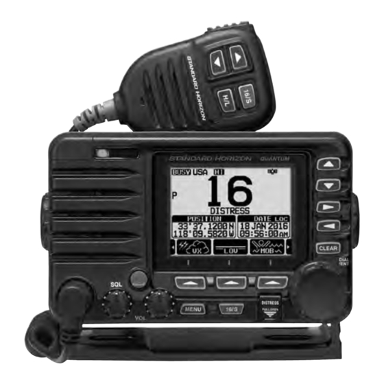
QUANTUM AIS GX6000
25 Watt VHF/FM
Marine Transceiver
Owner's Manual
Advertisement
Table of Contents

Subscribe to Our Youtube Channel
Related Manuals for Standart Horizon QUANTUM AIS GX6000


Summary of Contents for Standart Horizon QUANTUM AIS GX6000
- Page 1 QUANTUM AIS GX6000 25 Watt VHF/FM Marine Transceiver Owner’s Manual z Capable of connecting two optional wired RAM4 or one wired RAM4 and up to four Wireless RAM4W remote access microphones using SCU-31 wireless access point z Integrated NMEA 2000 interface supporting all PGNs for Navigation, GPS, AIS and DSC functions...
-
Page 2: Table Of Contents
TABLE OF CONTENTS Quick Reference Guide ........2 9 GPS OPERATION ........47 DISPLAYING POSITION INFORMATION ....47 1 GENERAL INFORMATION ......3 CHECKING GPS STATUS ......... 47 2 PACKING LIST ..........4 GPS LOGGER OPERATION ........48 3 OPTIONAL ACCESSORIES ......4 4 ONLINE WARRANTY REGISTRATION 10 DIGITAL SELECTIVE CALLING (DSC) .. - Page 3 TABLE OF CONTENTS 16.6 MULTI WATCH ............112 24.3 RECEIVER (for Voice and DSC) ......146 16.7 PRIORITY CHANNEL ..........112 24.4 RECEIVER (for AIS) ..........147 16.8 SUB CHANNEL ............112 24.5 NMEA INPUT/OUTPUT ..........147 16.9 CHANNEL NAME ............. 112 24.6 SCU-31 EXTERNAL GPS ANTENNA (Optional) ..
-
Page 4: Quick Reference Guide
uick efeRence uide The GX6000 is equipped with the E2O (Easy-To-Operate) menu system. Basic operation may be accomplished by following the procedure below: key to turn on or off the radio. Press and hold the The MODE/STATUS indicator indicates the status of the transceiver. ... -
Page 5: General Information
1 GENERAL INFORMATION The STANDARD HORIZON GX6000 Marine VHF/FM Marine transceiver is designed to be used in USA, International, and Canadian Marine bands. The GX6000 can be operated from 11 to 16 VDC and has a switchable RF output power of 1 watt or 25 watts. The GX6000 integrates a dual channel AIS (Automatic Identification System) receiver to display class A and B AIS vessel information (MMSI, Call Sign, Ship Name, BRG, DST, SOG and COG) directly on the LCD display. -
Page 6: Packing List
2 PACKING LIST When the package containing the transceiver is first opened, please check it for the following contents: Transceiver GX6000 Speaker Microphone DC Power Cord Mounting Bracket and Hardware Owner’s Manual DSC Warning Sticker USB Cable (Type USB “A”... -
Page 7: Getting Started
5 GETTING STARTED PROHIBITED COMMUNICATIONS The FCC prohibits the following communications: • False distress or emergency messages: • Messages to “any boat” except in emergencies and radio tests; • Messages to or from a vessel on land; • Transmission while on land; •... -
Page 8: Coaxial Cable
COAXIAL CABLE VHF antennas are connected to the transceiver by means of a coaxial cable – a shielded transmission line. Coaxial cable is specified by its diameter and construction. For runs less than 20 feet, RG-58/U, about 1/4 inch in diameter is a good choice. For runs over 20 feet but less than 50 feet, the larger RG-8X or RG-213/U should be used for cable runs over 50 feet RG-8X should be used. -
Page 9: Calling Another Vessel (Channel 16 Or 9)
8. Give your vessel’s description: length, design (power or sail), color and other distinguishing marks. The total transmission should not exceed 1 minute. 9. End the message by saying “OVER”. Release the microphone switch and listen. 10. If there is no answer, repeat the above procedure. If there is still no response, try another channel. -
Page 10: Making Telephone Calls
After a transmission, say “over,” and release the microphone’s push-to-talk (PTT) switch. When all communication with the other vessel is completed, end the last transmission by stating your Call Sign and the word “out.” Note that it is not necessary to state your Call Sign with each transmission, only at the beginning and end of the contact. -
Page 11: What Is The Range For Ais Receivers
West Coast Sea Tow Newport/LA - Ch. 27 Sea Tow San Diego - Ch. 27 Sea Tow Portland-Midcoast (Maine) - Ch. 27 Northeast Sea Tow Boston - Ch. 27 Sea Tow South Shore (Mass.) - Ch. 28 Sea Tow Rhode Island - Ch. 24 Sea Tow Eastern Long Island - Ch. -
Page 12: Controls And Indicators
6 CONTROLS AND INDICATORS This section defines each control of the transceiver. See illustration below for location of controls. For detailed operating instructions refer to chapter 8 of this manual. FRONT PANEL ... - Page 13 MENU key Press to access MENU. For details, refer to section “8.4 BASIC OPERA- TION OF THE MENU MODE”. 16/S key Pressing this key immediately recalls channel 16 from any channel loca- tion. Holding down this key selects the SUB channel (The default setting is channel 9).
-
Page 14: Microphone
MODE/STATUS indicator Indicates the radio status with the four colors on the three positions of the mode/status indicator. Position Color Description Blue AIS-Board Working Purple Receiving MSG23 Left AIS-Board Failed AIS Receiving (registered MMSI) Green Orange AIS Receiving (unregistered MMSI) Right Receive Error DATA jack... - Page 15 When an optional RAM4 and RAM4W mic is connected and intercom mode is selected, pressing the PTT switch enables voice communications from the GX6000 to the RAM4 and RAM4W second station microphone. Microphone speaker Audio heard through internal radio speaker is heard through the speaker microphone.
-
Page 16: Rear Panel
REAR PANEL VHF ANT jack (VHF antenna jack) Connects an antenna to the transceiver. Use a marine VHF antenna with an impedance of 50 ohms. Note: This ANT jack is used to marine voice channel. ... - Page 17 RAM-1/RAM-2 Remote Access Microphone Connectors Connects the GX6000 to the SSM-70H (RAM4) Remote Station Micro- phone or SCU-30 Wireless Access Point for use with up to four SSM-71H (RAM4W) wireless microphones. Refer to section “19 SSM-70H (RAM4) REMOTE MIC OPERATION” for details. ...
-
Page 18: Installation
7 INSTALLATION SAFETY / WARNING INFORMATION This radio is restricted to occupational use, work related operations only where the radio operator must have the knowledge to control the exposure conditions of its passengers and bystanders by maintaining the minimum separation distance of 3 feet (1 m). - Page 19 Overhead Mounting Desktop Mounting 7.3.2 Optional MMB-84 Flush Mount Bracket 1. Use the template (page 153) to mark the location where the rectangular hole is to be cut. Confirm the space behind the dash or panel is deep enough to accommodate the transceiver (at least 6.7” (17 cm) deep). There should be at least 1/2”...
-
Page 20: Electrical Connections
ELECTRICAL CONNECTIONS CAUTION Reverse polarity battery connections will damage the radio! Connect the power cord and antenna to the radio. Antenna and Power Supply connections are as follows: 1. Mount the antenna at least 3 feet (1 m) away from the radio. At the rear of the radio, connect the antenna cable. -
Page 21: Connection Of External Devices
Ferrite Core (Large) Snap together Speaker Code DC Power Code Snap together Ferrite Core (Small) As close as possible Fuse Replacement To take out the fuse from the fuse holder, hold both ends of the fuse holder and pull the fuse holder apart without bending the fuse holder. - Page 22 • If 4800 baud (default) is selected: The Blue and Green wires of input are at 4800 baud. • If 38400 baud is selected: The Blue and Green wires of input are at 38400 baud. NMEA Output (DSC and GPS information) •...
- Page 23 7.5.4 NMEA 0813/NMEA 0183-HS to Chart Plotter 4800 Baud Connections External GPS Antenna SCU-31 (optional) Radio Wires Plotter Connection GPS Chart Plotter Blue: NMEA IN ( + ) No Connection Green: NMEA IN ( − ) No Connection Gray: NMEA OUT ( + ) NMEA IN ( + ) Brown: NMEA OUT ( −...
- Page 24 7.5.5 Connection to External GPS or Chart Plotter 4800 Baud Connections Radio Wires Plotter Connection GPS Receiver Blue: NMEA IN ( + ) NMEA OUT ( + ) Green: NMEA IN ( − ) NMEA OUT ( − ) Gray: NMEA OUT ( + ) NMEA IN ( + ) Brown: NMEA OUT ( −...
- Page 25 7.5.6 Connection to External PA/HAIL Speaker GREEN PA 1 Speaker (horn) BLUE ORANGE PA 2 Speaker (horn) YELLOW External Speaker WHITE Wire Color/Description Connection Examples RED - External Speaker (+) Positive wire of external 4 Ohm External speaker WHITE - External Speaker (−) Negative wire of external 4 Ohm External speaker GREEN - PA1 Speaker (+) Positive wire of external 4 Ohm audio speaker (horn)
- Page 26 Optional SSM-70H (RAM4) Installation The GX6000 is capable of using two SSM-70H (RAM4) Remote Station Microphones to remotely control the Radio, AIS, DSC and PA/Fog functions. In addition the GX6000 can operate as a full function intercom system between the SSM-70H (RAM4) and the GX6000. WARNING Do not connect or remove the SSM-70H (RAM4) microphone while the radio is powered on.
- Page 27 4. Finally, wind some plastic tape around each ferrite core, to prevent vibration from causing the two halves to split apart. 5. Referring to illustration right, make a 1.2” (30 mm) hole in the wall, then insert the extension cable External Speaker Connections into this hole.
-
Page 28: Initial Setup Required When Turning
4. Rotate the DIAL/ENT knob to select “SPEAKER SELECT”, then press the [SELECT] soft key. 5. Rotate the DIAL/ENT knob to select “INTERNAL” or “EXTERNAL”, then press the [SELECT] soft key. 6. Press the CLEAR/ key to return to radio operation. INITIAL SETUP REQUIRED WHEN TURNING ON THE POWER FOR THE FIRST TIME 7.6.1... - Page 29 Programming the MMSI 1. Press the MENU key to display “MENU”. 2. Rotate the DIAL/ENT knob to select “MMSI/POS INFO”, then press the [SELECT] soft key. (To cancel, press the [BACK] soft key.) To view your MMSI to ensure it is correct, perform steps 1 to 2.
-
Page 30: Checking Gps Signal (Gps Status Display)
CHECKING GPS SIGNAL (GPS STATUS DISPLAY) When the GX6000 receives the GPS signal from the optional SCU-31, a small satellite icon “ ” will appear on the display and your current location (latitude/ longitude) is shown on the display. (*When the GPS signal receiving from the NMEA 2000 or NEMA-0183, a “2K”... -
Page 31: Gps Configuration
GPS CONFIGURATION 7.8.1 Changing the GPS Time The GX6000 shows GPS satellite time or UTC (Universal Time Coordinated) time in factory default. A time offset is needed to show the local time in your area. The time offset must be changed in order for the radio to display the current time in your area. - Page 32 4. Rotate the DIAL/ENT knob to select “TIME AREA”, then press the [SELECT] soft key. 5. Rotate the DIAL/ENT knob to select “UTC” or “LOCAL”. 6. Press the [ENTER] soft key to store the selected setting. 7. Press the CLEAR key to return to radio operation. 7.8.3 Changing the Time Format This menu selection allows the radio to setup to show time in 12-hour or...
Need help?
Do you have a question about the QUANTUM AIS GX6000 and is the answer not in the manual?
Questions and answers