Table of Contents
Advertisement
1721_Betra_21_6915_0101.qxd
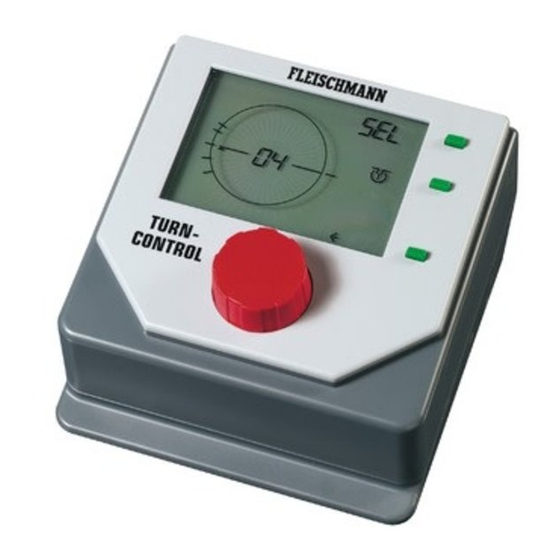
6915 TURN-CONTROL
Turntable Controller
Operating instructions
Contents
1.
2.
3.
4.
27.09.2007
Page
GB
26
27
29
29
31
32
36
40
42
46
48
12:15 Uhr
Seite 25
Dear Railway Modeller,
Thank you for deciding to purchase the TURN-
CONTROL turntable controller
FLEISCHMANN. The controller can be used for
any of the FLEISCHMANN turntables (as well as
Märklin* 7286) either in DC powered or digital
systems and even in 3-rail AC layouts, so that you
can pre-select your desired turntable exit tracks
and automatically rotate the turntable to them.
The TURN-CONTROL can even be operated by
DCC equipment or via LocoNet connections.
You won't need to make any alterations either to
the layout or directly to the turntable itself.
In this operational manual, we will describe, step
by step, all you need to know about how to install
and how to use, (i.e. connection to additional
turntables) the TURN-CONTROL controller on
your layout.
The FLEISCHMANN-Team wish you many hours
of enjoyment with your new controller.
* Märklin is a registered trademark of the Company of Gebr. Märklin&Cie GmbH, Göppingen
6915 from
25
Advertisement
Table of Contents

Related Manuals for Fleischmann TURN-CONTROL

Summary of Contents for Fleischmann TURN-CONTROL
-
Page 1: Table Of Contents
Thank you for deciding to purchase the TURN- CONTROL turntable controller 6915 from FLEISCHMANN. The controller can be used for any of the FLEISCHMANN turntables (as well as 6915 TURN-CONTROL Märklin* 7286) either in DC powered or digital Turntable Controller... -
Page 2: Safety Warnings And Advice On Use
(transformer: not included in delivery). Safety Warnings In the interests of safety in operation as well TURN-CONTROL 6915 is not designed for as the enjoyment of the equipment itself, use by children under the age of 3. please read this operational manual through Under no circumstances, connect the completely. -
Page 3: Components, Operational Elements And Connections
27.09.2007 12:15 Uhr Seite 27 What can you operate by using the TURN- Components, operational CONTROL? elements and connections All FLEISCHMANN DC turntables, in all scales First all, please check through of 00/HO, TT and N gauge, with or without components of your TURN-CONTROL as switchable track exits ("C"... - Page 4 Connect up the wires first of all and then plug in the transformer. If you wish to use the TURN-CONTROL digitally or via the LocoNet connection, then you will also need a suitable length LocoNet cable! The FLEISCHMANN article 6887 (2.15 m long) and...
-
Page 5: Operation
1 turntable, either 6052 (C), 6152 (C), 6154 (C), conection to the TURN-CONTROL, or on the 6651 (C), 6652, 6680 (C), 9152 (C), Märklin 7286 other, you can use the LocoNet connection (3-rail AC operation). - Page 6 12:15 Uhr Seite 30 To make a secure connection, use a small B) For connecting up a FLEISCHMANN turntable screwdriver to press down on the spring tension 6652 for 3-rail AC operation (Märklin system), clamp of the relevant socket (see Fig. 3) and feed...
-
Page 7: Connection To A Transformer
Thus it is not possible to "mix up" the connections when inserting the plug. Now the TURN-CONTROL is connected up and ready for use. Now we will create the power feed for the TURN- CONTROL. You can feed the TURN-CONTROL either with DC or AC power so long as the power is continuous, between 14 volts and 16.5 volts. -
Page 8: Operation And Menu Options
Please carry out the following procedure exactly, step by step, so that it is done correctly. Remove the protective packaging foil from your TURN-CONTROL. We are now going to put into To operate your TURN-CONTROL there are the TURN-CONTROL the actual situation of your... - Page 9 27.09.2007 12:15 Uhr Seite 33 Advice: selection/confirmation The display of the TURN-CONTROL shows the depressing the red knob will be indicated by a turntable on the layout and gives information on symbol " " in the display next to the its current position, numbers of the track exits, corresponding green key.
- Page 10 1721_Betra_21_6915_0101.qxd 27.09.2007 12:15 Uhr Seite 34 The first step is to let your TURN-CONTROL Advice: If the display shows that you have turned know how many track exits your turntable has as further than the desired selection, then you can a maximum.
- Page 11 1721_Betra_21_6915_0101.qxd 27.09.2007 12:15 Uhr Seite 35 selection by pressing the red knob. should be live – either the bridge hut side (left arrow) or on the opposite side (right arrow). The next step is to synchronise the position of the The selection is made using the green key bridge hut in the display with the actual current beneath the symbol <-->.
-
Page 12: Using The Controller
"9 o’clock", with the bridge in the correct As the second step, you must now put position! into the TURN-CONTROL the actual Advice: If not, turn the red knob to the desired track exit positions which you have position so that the bridge symbol in the display on your layout, for example, with turns with it. - Page 13 In the same way, we can now put the next track number, in our case, the number "1". exits (Nos. 2 to 4) into the TURN-CONTROL. Turn the red knob until the number "01" blinks in the display in place of the indication "00" (Fig.
- Page 14 1721_Betra_21_6915_0101.qxd 27.09.2007 12:15 Uhr Seite 38 After this step, your display should look like that shown in Fig. 12. Fig. 11 Create 2nd exit Confirm! The left hand side of the bridge symbol will now Fig. 12 2. Put in 2nd exit blink.
- Page 15 1721_Betra_21_6915_0101.qxd 27.09.2007 12:15 Uhr Seite 39 Turn the red knob until the number "03" appears in the display. Confirm! Your display should now look like this (see Fig. 13): Fig. 14 Go to the 4th exit Confirm! After turning the red knob again, a new tiny strip will appear beside the bridge hut symbol.
-
Page 16: Play Mode
(programmed) exit numbers. We have now told the TURN-CONTROL all it needs to know about the tasks it has to perform, so we can now proceed to the next section on how to use it. - Page 17 "<-->". This will change the choose the shortest direction to rotate. active side of a C-bridge. If the active side is lined up with a programmed track exit, the TURN-CONTROL stores information number of this exit will also be displayed. The internally whether a selected target position has active exit section will blink.
-
Page 18: Special Functions
If the equipment is switched 2.6 Special Functions off and it is not in the correct selected position, Within the menu options of the TURN-CONTROL , then on being switched on again an error code by pressing the upper green menu key, will be displayed (see appendix). - Page 19 Without changing the polarity, there In the menu CH1 (Check 1) you can test your would be a short circuit with the exit tracks! turntable. This will allow the TURN-CONTROL to Go into the POL menu. "learn" the running characteristics of your using the red knob, rotate the bridge into the turntable and fits in with it.
- Page 20 1721_Betra_21_6915_0101.qxd 27.09.2007 12:15 Uhr Seite 44 intervals as long as you keep the key pressed) In the menu option rEL, the bridge power can be "Pro", "CnF", "POL" and "rEL", when " " turned on or off using a small relay. will blink in the dispay.
- Page 21 The equipment will check immediately and digital operation of the TURN-CONTROL. according to its findings, will indicate the result in the display (where normally the exit numbers are shown) of the TURN-CONTROL by the following code numbers: neither LocoNet nor DCC found, LocoNet found, DCC found, LocoNet and DCC found.
-
Page 22: Digital Operation
3. Digital operation A 180° rotation of the bridge, left or right can be started with the electrical accessory address 200: You can operate the TURN-CONTROL with any red-right (clockwise), green-left (anti-clockwise). LocoNet compatible digital central controller (i.e. TWIN-CENTER 6802) and DCC Systems. - Page 23 1721_Betra_21_6915_0101.qxd 27.09.2007 12:15 Uhr Seite 47 The TURN-CONTROL will not react to a reset via be used by other electrical accessories on your DCC or LocoNet, it will continue to function as layout. normal. Advice: Using TWIN-CENTER 6802, version 1.0 LocoNet commands have precedence over and 1.1, at first you must assign the electrical...
-
Page 24: Appendix
1721_Betra_21_6915_0101.qxd 27.09.2007 12:15 Uhr Seite 48 4. Appendix TURN-CONTROL-DCC-addresses of the track exits. This appendix shows some of the specialities of Digit. Addr. exit 1 exit 2 exit 3 exit 4 the TURN-CONTROL. Errors will be indicated in the display with this symbol "...
Need help?
Do you have a question about the TURN-CONTROL and is the answer not in the manual?
Questions and answers