
Summary of Contents for Tryax TY30-VS
- Page 1 TRYAX Vertical Diamond Cut Alloy Wheel Lathe Operation Manual USA TY30-VS Model: Tryax Limited Jubilee Trade Centre,Jubilee Road,Letchworth Garden City,Herts,SG6 1SP,UK Phone +44(0) 1462-481295 Fax +44 (0) 1462-685275 www.tryax.com...
-
Page 2: Table Of Contents
Forced Auto Lubricator ....................26 6. Troubleshooting ....................29 Machine Troubleshooting .................... 29 Quick-Wear Part List ....................30 7. Machine Parts List ..................... 31 Tryax Limited Jubilee Trade Centre,Jubilee Road,Letchworth Garden City,Herts,SG6 1SP,UK Phone +44(0) 1462-481295 Fax +44 (0) 1462-685275 www.tryax.com... -
Page 3: Safety Notes
Safety Notes Safety Specification This machine is equipped with safety devices designed to protect operators from being hurt or the machine being damaged. Operators should thoroughly read this Manual as well as undergo the compulsory training programme before operating this Machine. Ensure there is sufficient space around the Machine to open the electrical-box door for maintenance/repair and space to allow normal access to and from the machine. -
Page 4: Notes After Operation Stops
Notes after Machining Operation Stops Before opening the Access Doors, be sure that the chuck has stopped turning. After the dry-cutting process is complete and before removing the workpiece, be sure to put on safety gloves (to avoid skin-burn). Notes on Handling Abnormal Status Once an abnormal status occurs, press the emergency stop button immediately. -
Page 5: Noise
Noise Per ISO/DIS 230-5 Standard, noise of Machine either at stationary or running status should be lower than 80 dBA. If over this level, inform us immediately to correct the Machine. The inspection positions are shown in the figure below. Measurement standard: according to Machinery Directive 98/38/CE Annex I article 1.7.4(f) specification. -
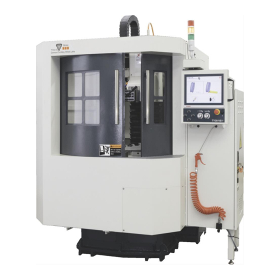
Page 6: Machine Brief Introduction
Machine Brief Introduction Mechanical Specification TY30-VS SPECIFICATION Model Unit VTL30 Control Control System BECKHOFF X-axis Travel mm(inch) 508(20") Travel Z-axis Travel mm(inch) 457(18") Max.Turning Diameter mm(inch) 762(30") Table Jaw Chuck(Manual)with Soft Jaw inch 16" - 3 Distance from Spindle end to Table mm(inch) 0-457(0~18") -
Page 7: Machinery Outline Scheme Diagram
2.2 Machinery Outline Scheme Diagram... -
Page 8: Assembly Drawing & Machine List
Assembly Drawing & Machine list... -
Page 9: Foundation Plan
Foundation Plan... -
Page 10: Mechanical Coordinate System
Mechanical Coordinate System Axis-definitions are expressed in below: X-axis: X-axis is the direction that tool post moves right/left; (+) for right movement and (-) for left one. Z-axis: Z-axis is the direction that tool post moves up/down; (+) for up movement and (-) for down one. -
Page 11: Jaw Chuck Size
2.6 Jaw Chuck size 2.7 Tool Holder Dimension Drawing... -
Page 12: Move, Store And Install The Machine
3. Move, Store and Install the Machine Pre-installation Preparation Works Power source: required power supply specification: Power Voltage Frequency Phase Specification 220V 60 HZ 3+Neutral+Earth Pneumatic - air pressure used to clean up spindle, cool down cutting is 5 ~ 7 KG/CM at least 90 NL/min of supply. -
Page 13: Unload And Moving The Machine
Unload and Moving the Machine Unload the Machine package: (refer to the pictures below) The Machine is mounted on a stillage, use forklift to unload the package from container. Unload the Machine as shown in the pictures:... - Page 14 Removing the machine from the pallet: a. Remove the 2- covers in front of X axis cover. Insert a steel bar inside the machine base. (See the figure below) b. Pass a chain through the 2 openings and loop the chain around the steel bar from both side of the machine.
-
Page 15: Installation & Levelling
3.3 Installation and Levelling 3.3.1.Machine leveling adjustment Use the leveler 0.02 mm/m on the center of the chuck,fix the leveler on the X axis direction and manualy turn the chuck, adjust the level of X axis until the air bubble in the leveler is centered. Repeat for Z axis. -
Page 16: Install The Peripherals
3.3.2 Install the Peripherals Installing steps of peripherals Steps Explanation Compressed air Connect air supply to input point. source Filling track Fill lubrication system.. lubricants Remove the mount Remove the mount blocks in X- & Z-axis; don’t remove the block wooden block that supports the spindle head. -
Page 17: Power Requirement
Power Requirement Power and ground Main power input 3 phase 415V with Neutral and earth 32 Amps per phase Single Phase Not Required Notes on installing power source and grounding work Do not co-use power cable with other machines. Provide an independent power line for this Machine. -
Page 18: Compressed Air Source
Compressed Air Source Use clean air source. Confirm that the air source can provide necessary air flow-rate. Air pressure should exceed 6 kg/cm Arrangement of reserved pipelines: Compressed air must be filtered and be clean and dry (dew point, 6 kgf/cm 10°C). -
Page 19: Pre-Boot Preparation Works
Pre-boot Preparation Works Pre-boot Check In order to ensure the safety of operators and Machine, check the following items before booting Check if oil in the lube oil tank is sufficient? Ensure that space around the Machine and control system is clear. Ensure that every panel and door is closed. -
Page 20: Oil-Feed And Oil Types
Oil-feed and Oil Types The Machine two axis guide-ways and ball screw are under forced-lubrication operation with auto oil-feeding. Prior to booting, check if lube oil is sufficient. Always use the correct lube oil; incorrect oil will reduce Machine’s lifetime and may cause malfunction. -
Page 21: Chips Conveyor System
Chips Removal Manually clean the chips, sweep the chips to the front left corner where the chip tank located. -
Page 22: Machine Maintenance And Tuning
Machine Maintenance and Tuning Maintenance Period 5.1.1 Maintenance Interpretation Regular maintenance can extend Machine’s operation lifetime and maintain its working efficiency. In this section we’ll provide the maintenance methods of systems/units and suggested maintenance schedule. When performing maintenance, substantially obey the methods/time presented in this section. - Page 23 Machine regular maintenance frequency list (3/3) Maintenance work content Remark Check lube oil level Check oil-feed pressure Check indicators on panel Check switches on panel Clean up heat exchanger filter Clean electrical box Clean electrical components Lock up devices in electric-box Clear jaw chuck chips Clear machine chips Clean up chips in X-, Z-axis cover...
-
Page 24: Maintenance Check Sheet
5.1.3 Maintenance Check Sheet 1. Daily maintenance sheet Model/Machine No.: Maintenance date: Confirmed: Daily maintenance Maintenance Maintenance work Checked/confirmed Item Remark type Check air pressure of air-pressure □Accomplished □Not performed DWMHY regulator Clean up chips in chips tank □Accomplished □Not performed DWMHY Check if oil in oil-feeder is sufficient □Accomplished □Not performed... - Page 25 3. Monthly maintenance sheet Model/Machine No.: Maintenance date: Confirmed: Monthly maintenance Maintenance Maintenance work Checked/confirmed Item Remark type Clean fan filter □Accomplished □Not performed Clean up dust and foreign matter in □Accomplished □Not performed electrical-box Clean up dust on electric devices □Accomplished □Not performed Adjust and lock up electric devices □Accomplished □Not performed...
-
Page 26: Soft Jaw Chuck Mechanism
Soft jaw chuck Mechanism Forced Auto Lubricator Electric Lubricator specification Lubricating Intermediate Maximum Maximum Type time time flow-rate pressure JY19B 1-99 sec. 1-99 min. 180 c.c/min 8 kg/cm Floating-ball Three-phase Motor output Connector Oil tank capacity switch voltage power diameter ... - Page 27 1. Lube oil unit loop 2. Oil-feeding method and feeding adjustment This Machine applies forced oil-feeding. Oil supply may be operated automatically or manually. Manual oil feeding: after pressing the start button, pump motor runs to feed oil out; release the button to stop pump. Auto oil feeding: when Machine power is on, oil feeder is under oil-feeding status;...
- Page 28 4. Troubleshooting of lubrication unit Item Fault status Reason Troubleshooting method 1. Pipeline is clogged. 1. Clean up or replace pipeline. 2. Lube oil viscosity is too high. 2. Change to approvedoil. 3. Filter net is clogged. 3. Remove clogging. 4.
-
Page 29: Troubleshooting
Troubleshooting Machine Troubleshooting Item Fault reason Factor Handling method 1. Lack of oil. 1. Renew or supplement oil. 2. Wrong oil applied. 2. Use SHELL R68 guide-way oil. 3. Oil flow-rate. 3. Noise is shown; need to be replaced. X-axis shakes 4. -
Page 30: Quick-Wear Part List
Quick-Wear Part List... -
Page 31: Machine Parts List
Machine Parts List... - Page 32 Drawing No. Name Specification Material Quantity WL30VSB001A Base FC25 WL30VST002A Soft Jaw 6061 WL30VST001 Chuck SK-16 Purchase products WL30VSB029 Chuck adapter plate S45C WL30VSB021 Spindle the front cover SS41 WL30VSB022 Principal axis S45C Hex socket cap screws M14x50 Purchase products Hex socket cap screws M10x40 Purchase products...
- Page 33 Drawing No. Name Specification Material Quantity SD07011060 Power lock DL-SD-70 Purchase products SD03806542 Power lock DL-SD-38 Purchase products LD30512005 V Belt 5PK 1300mm Purchase products EM00210004 Induction Motor 10HP/4P Purchase products WL30VSB025 Telescopic covers Purchase products KT10505520 T1-oblique block Purchase products NC0020 Hit the block Purchase products...
- Page 35 Drawing No. Name Specification Material Quantity WL30VSC001A Column FC25 Z841011 limit switch Purchase products WL30VSEC005 limit switch fixed plate SS41 KT10505520 T1-oblique block Purchase products WL30VSC004 Nut seat SS41 B620402002 TAC-Bearing Purchase products BD1102B014 Fixed-Side rectanglar FC25 WL30VSC002 Linear guideway MSR25 Purchase products WL30VSC003...
- Page 37 Drawing No. Name Material Quantity WL30VSH001 Z-axis slide SS41 WL30VSH002 Quartet turret Purchase products WL30VSH003A Turret seat SS41 WL30VSH013 Tool mounting block SS41 WL30VSH014 Cutters Purchase products WL30VSH018 Probe handle SS41 WL30VSH021 Probe socket SS41 WL30VSH023 Tool positioning sheet metal SS41 WL30VSC004 Nut seat...
Need help?
Do you have a question about the TY30-VS and is the answer not in the manual?
Questions and answers
Hi how do we set the spindle speed
The Tryax TY30-VS has automatic spindle speed control. The system automatically sets the spindle speed as part of its digital optimization features.
This answer is automatically generated