Table of Contents
Advertisement
Advertisement
Table of Contents

Subscribe to Our Youtube Channel
Summary of Contents for Ateco AT-301
- Page 1 www.adae.store service@adae.store...
- Page 2 AT - 301 Manual Before attempting to connect or operate this product, please read these instructions completely! Version:1.00...
-
Page 3: Table Of Contents
Contents 1. ATECO AT-301 General Introduction..................1 1.1 Functional Components......................1 1.11 AT-301sensor....................... 1 1.12 Control Box.........................2 1.2 Technical Specifications......................3 1.3 Sharing the Sensor Between Rooms..................3 1.4 Using the different Positioning Systems................3 2. Imaging Software General Introduction..................4 2.1 Computer System Requirements...................4 2.2 Imaging Software......................... - Page 4 14.6.1 Operating conditions....................40 14.6.2 Transport and Storage conditions................40 15. Waste Electrical and Electronic Equipment................41 15.1 Background........................41 15.2 WEEE Marking......................... 41 15.3 Reporting...........................41 15.4 WEEE from Users other than Private Households............42 15.5 Information for Reuse Centers, Treatment and Recycling Facilities....... 42 15.6 Warning and Safety Instructions..................
-
Page 5: Ateco At-301 General Introduction
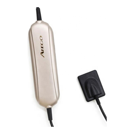
1. ATECO AT-301 General Introduction Dental digital x-ray imaging system is consisted of sensor, image controller, image capture system and connection cable (USB port) , connected with PC or notebook via USB cable. The power of controller and sensor is supplied by USB port, require no battery or power charge system. -
Page 6: Control Box
Figure 3 1.2 Technical Specifications Sensor: APS CMOS sensor External dimension (mm) :44×32() ; 40×26(AT-301) Sensor Active Area : 36×27() ; 30×22.5(AT-301) Sensor Thickness : 6mm Dynamic Range : 0~4,096 Power : 5V±0.5V Image Transfer :USB2.0 Cable Length :.≥... -
Page 7: Using The Different Positioning Systems
To share data between rooms, you can connect them to remote data---ATECO Server database. The ATECO Dentist dental imaging software needs only to access a shared database on the same computer or on a remote computer, which means ATECO Server database. -
Page 8: Imaging Software General Introduction
Operating System: Windows XP The computer connected to system shall be in accordance with IEC 60950-1:6005. 2.2 Imaging Software The Ateco AT-301 dental imaging system operates with the following software: Atecotech Atecotech Server for sharing information between workstations. Atecotech Software is a user-friendly working interface that was designed and developed specifically for radiological diagnosis. -
Page 9: Driver Installation
3. Driver Installation 1. Insert the CD into CD-ROM or DVD drive , browse CD then double click on the icon to continue. It will show 2. Click , it will show 3. Click , it will show... - Page 10 4. lick , it will show 5. Cl...
-
Page 11: Software Installation
, the driver is installed. Then connect the sensor to computer via USB cable, the computer will recognize it, and will show it is ready to use. 4. Software Installation Double-click on the My Computer icon on your desktop, then open the CD-ROM drive by double clicking. - Page 12 2. Choose the required language. 3. Click on the button 4. The default destination folder is “D: /Atecotech”. If you want to change the route, please click on the button of to select the folder you want. Then click on , and then it shows...
- Page 13 5. Click on , then it shows. There are two selections for creating the icon, please make the selection according to your needs click , then it shows: 6. Click on the button , then it shows:...
- Page 14 7. Click on the following window will be shown: 8. When the installation is finished, the following window will be show:...
-
Page 15: Install Calibration File
9. Then click on the button , the whole installation was completed and the software will be launched automatically, and there will be a shortcut on the desktop. 5. Install Calibration File Install To Atecotech Provided with every sensor is a disk containing the sensor calibration file. Each calibration file is unique to the sensor it was shipped with and the file must be installed on every computer systems before using that sensor. - Page 16 6. Register Key 30 days later since the date of software installation, the software will ask for register. Double click on the target frame, register key windows will come. Please remember to register the software within 30 days of installation. Click on Help in menu bar then select Register .
-
Page 17: Software Operation
7. Software Operation User interface Double click on the icon to launch the software, the Atecotech window will be shown: Example Screen: 1.System menu of the program windows 2.Menu bar 3.Tool bar 4.Patient account list 5.Teeth chart 6.Target frame 7. Image information Menu Bar Each item contains a drop-down menu, and some of function can be achieved directly from the icon in toolbar... - Page 18 Click on Display, then select the your target language. In Recent history part, there are two options, it arranges the order of First name and Last, this depends on countries custom . Please click on OK, it will show Click OK, the software will be restarted automatically and switch to be the language you selected.
- Page 19 Toolbar Each button contains a icon and will show a short message to explain corresponding function by moving the mouse pointer to the icon. Establish Patient account 1. Click the icon in the toolbar or select new patient in file of menu bar Then it will show Input patient information ,select picture series and you can also input study comments in the frame and then click on OK .
- Page 20 Target frame (18 pcs) If the first one is full (Maximum 20 images for each account ) Click on for creating another account under the same patient. For establishing a account for another patient , please select “ new patient ” in this windows A new patient case has been created successfully.
- Page 21 Delete patient account Please select the patient case that you want to delete it will show the following notice window Click on “Yes”, and this patient will be deleted. Search a patient case Click on this icon, and input the patient information, the target patient patient will be showed.
- Page 22 Click on this icon to view the image one by one. The default time is 3 seconds and it could be changed depend on your requirement. Press “ESC” to exit. Edit Image Select a image then click on this icon to open “ ATECO Image” windows, and you...
- Page 23 can also open it with double-click on the image. More information refers to 9.3. Delete Image Select the image you want to delete then click on this icon. The following windows will show Choose “yes” or “no” to delete the image or not. Export Image Select a captured image then click on this icon to export this image.
-
Page 24: Acquiring An Image
bar directly. Print more images: Keep on pressing the “ctrl” on the keyboard and then left click on the target frames to select several frames at the same time, then click on this icon to print these selected images. * Before use the hardware, please chick the equipment icon first: The icon is for Intraoral Camera or Film Reader. -
Page 25: Launching The X-Ray
3 Select the x-ray timing according to the region of interest and the patient type (follow the user instructions of your x-ray generator). 4 Insert the sensor holding it horizontally in the patients mouth. Positioning in the patient’s mouth depends on region of interest. 5 Approach the x-ray generator tube head to the patient. - Page 26 The image has been captured and the information frame return back to green color. It’s ready to capture another image, without closing the window. As soon as the image was captured it will be saved into software. 5. Check the image quality. If not satisfactory, redo the x-ray. 6.
- Page 27 The capture windows will come and appear flash green light (default setting) . The sensor ID # of the sensor you are using is shown directly on the title. And it will remind you if the calibration file hasn’t been installed in the meanwhile.
- Page 28 The green flash frame will change to be yellow color , it means that the sensor has detected the x-ray successfully .And around two seconds later , the image will be captured as below show . Advanced Settings If you find out that some images need do some imaging process to enhance the image quality, you can use Advanced Settings...
- Page 30 And you can slide these buttons one the left to adjust to what you expect on the right side, and next time you will take the image just exactly you want to enhance without any other action. **However, we will recommend you keep the default figures in normal cases.** ** To optimize the final image processing quality, please adjust the window level first and save to a new picture, then using processing function buttons on this saved new picture.
-
Page 31: Ateco Image
The icon is for Panoramic Machine. ATECOImage(Enhance image) 9. Ateco Image For enhancing the original image quality please double click the target frame with image or click on the button of to come into ATECOImage. ATECO Image Toolbar To apply the function, click on corresponding button. - Page 32 Choose the display mode you prefer. This function is used to view the image from different angle . Click this button,there’s a small window for choosing the magnifier parameter you prefer. This function was set for making a mark on the image the pinot out the tooth problem and for better communication between patient and dentist.
- Page 33 Click on this Drawing icon, then keep on left pressing of mouse, then move the pointer on the picture, the red line will appear following the mouse pointer . Click on this icon, the following windows will show Left Click on two points that you want to know the distance. And left frame will show the distance, and this is only for reference, not accurate.
- Page 34 And if you calibrate the image taken from other brand sensor or intraoral camera, you will need calibrate first. Color Adjust Color adjusted by moving the slider either to left or right depending on your needs. Bright/Contrast Brightness and contrast could be adjusted also by moving the slider to left the to decrease the brightness/contrast, move the slider to right to increase.
- Page 35 Inverts the gray shades of the image-negative images appear as positive, and positive images as negative. Before Negative After Negative Click on the colorize button, you’ll notice the significant color contrast between different elements of the image.Because some differences can be easier to distinguish in color,colorizing provides antother means to identify potential problems areas during examnations.
- Page 36 Before Normalize After Normalize Removes fixed pattern noise from an image. Before Denoise After Denoise Make the images smoother Before Soft After Soft Simulation Diagosis In order dentist have a better dental practice and more easy to dignose for particular dentition. Saprodontia,Root Canal, Periodontal, Crown and Diagosis,four different enhanced image make easier to check.
-
Page 37: Troubleshooting Images
And With one button of Dignosis, you will see four different enhanced image. By Pressing this button the edited image will be saved automatically. And it will give the following notice. Click on (Y), the edited image will be saved into software automatically. 10. -
Page 38: Maintenance
The image is pale, too light The exposure time is too short; increase The generator voltage is too low; have the generator checked. The generator is too far from the patient with respect to the selected dose. Check the monitor setting (contrast and brightness) and ensure there are no reflections on the screen. -
Page 39: Cable Care
Check that there is no external damage to the product which could compromise its ability to operate safely Check the installation, then do the step 1, 2 and 5 of operation and check that the indicator lights and indicator area in software are in normal. 11.3 Cable Care Improper coiling of a sensor's cable is the most common cause of the sensor failure. -
Page 40: Warranty
Ateco Technology Ltd., the customer must return the faulty product at his own expense. Other than cost incurred for repair, cost of spare parts and labor, Ateco Technology Ltd. will only take on the cost of return to the delivery address initially communicated by the client. -
Page 41: Notice
,require to working with x-ray source and imaging software in dental clinic for dentist and orthodontists. 13.2 Brief Introduction of this Manual This manual consist of the safety issue, AT-301 brief introduction, software introduction, how to use sensor and the warranty policy. 13.3 Manufacturer... -
Page 42: Symbols
Waste Electrical and Electronic Equipment (WEEE) directive 6002/96/EC Conforms to European Union Medical Devices Directive (MDD) 93/42/EEC Label Location The following Figure indicates the label locations of The AT-301 and Systems. Figure 1 AT-301 and Label Locations... -
Page 43: Safety Issue
14. Safety issue 14.1 Check Sensor and controller before using them Before each usage, check the outer surface of the Sensor and controller for any signs of physical damage or defect. Sensor and controller surfaces should have a smooth finish, with no evidence of chipping or damage. If detected, contact your local distributor of this product for further instructions. -
Page 44: Safety Classifications
equipment and Listed / Approved / IEC 60950-1 certified Information Technology Equipment (ITE) computer equipment is acceptable. The host computer (PC workstation) should be CE-approved and conform to the Low Voltage [73/23/EC] and EMC Directive [89/336/ERC]. The system shall be in accordance with IEC60601-1-1. -
Page 45: Waste Electrical And Electronic Equipment
ATECO Medical and its Dealers are committed to complying with the Directive. 15.2 WEEE Marking All ATECO products subject to the WEEE Directive and shipped after August 13, 6005 will be compliant with the WEEE marking requirements. These products will be identified with the “crossed-out wheeled bin”... -
Page 46: Weee From Users Other Than Private Households
15.5 Information for Reuse Centers, Treatment and Recycling Facilities After August 13, 6005, and as required by the WEEE Directive, ATECO Medical or its Dealers will provide reuse, treatment, and recycling information for each type of new EEE put on the market within one year of the date in which the equipment is put on the market. -
Page 47: Hygiene And Disinfection Instruction
Nor intended for apply with flammable anesthetics or flammable agents.Using accessories other than those specified in this document with the exception of those sold by ATECO Health may result in a lower level of security for the entire system. For Computer: DO NOT place the computer and the peripheral equipment connected toit in the immediate vicinity of the patient in the unit.
Need help?
Do you have a question about the AT-301 and is the answer not in the manual?
Questions and answers