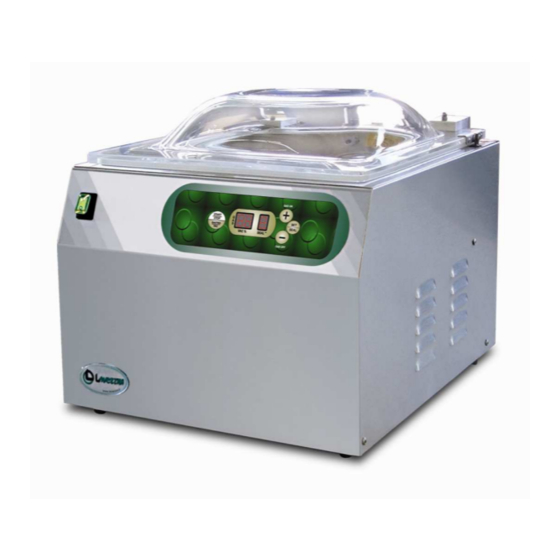
Summary of Contents for Lavezzini UNICA
- Page 1 VACUUM PACKAGING MACHINES VACUUM PACKAGING MACHINES VACUUM PACKAGING MACHINES VACUUM PACKAGING MACHINES « « « « UNICA UNICA UNICA UNICA » » » » INSTRUCTIONS HANDBOOK INSTRUCTIONS HANDBOOK INSTRUCTIONS HANDBOOK INSTRUCTIONS HANDBOOK...
-
Page 2: Vacuum Pump
PAY ATTENTION!! IMPORTANT!!!! WARRANTY RULES FOR OUR VACUUM PACKING MACHINES Dear Customer, In order to avoid any misunderstanding of our warranty policy, please note that the following item: VACUUM PUMP is not meant to be replaced by the supplier, even if within warranty time, without a previous return of the disputed part. - Page 3 CHAPTER 1 Identification of the “Instructions Handbook” The instructions handbook is a document issued by the manufacturing company and is an integral part of the machine. This document is adequately identified for easy tracing and/or subsequent references. All rights relating to the reproduction and disclosure of the information contained in this handbook and the documentation quoted and/or attached are reserved.
-
Page 4: Warranty
Care of the instruction handbook This document is an integral part of the machine. Preserve a copy of this instructions handbook for the entire working life of the machine even if transferred or sold to third parties. Requests for further copies of this document must be made by means of purchase order addressed to the manufacturing company. -
Page 5: General Safety Precautions
The manufacturing company engages, for 12 (twelve) months from the date of shipment and direct delivery of the goods, to assure the customer or concessionaire the integrity and the good working of the components regarding the above mentioned machine. All machine components normally subject to wear, that is to say components in which use causes a constant wear and tear, are not included in the warranty: A. -
Page 6: Installation
never touch the metal parts of the machine with wet or damp hands; do not pull the supply cable or the machine itself to disconnect the plug from the current outlet; children or unqualified personnel are not allowed to use the machine without supervision; electrical safety of the machine is ensured by its correct connection to an effective earthing as in accordance with the electrical safety standards in force;... - Page 7 Place Position the machine in a place with low humidity percentage and far from heat sources. DO NOT INSTALL THE MACHINE IN AN EXPLOSIVE ATMOSPHERE. DISCONNECT THE POWER SUPPLY PLUG FROM THE MAINS BEFORE STARTING ANY CHECKING OPERATION WHICH MAY REQUIRE PARTS DISASSEMBLY. Fig.
-
Page 8: Use Of The Machine
“START/ STOP” manual button: to activate the vacuum cycle once you have closed the lid. It is used also to make the vacuum in GN containers. DISPLAY VACUUM: vacuum setted in % ( vacuum max 98-99%) DISPLAY SEAL: setting of sealing time (about 2,5-3 sec.) SET button to change vacuum and sealing time when the machine is not working. - Page 9 3. Set the vacuum time (or percentage) required, the sealing time and the gas injection time (if the machine is equipped with such a system). 4. Position the bag (or bags) inside the vacuum chamber; put the bag opening perfectly flat on the sealing bar.
- Page 10 Beer/Can drinks Biscuits and oven products Coffee Fresh meat 70/80 30/20 Dehydrated meat and spices Minced meat Chocolate Fresh cheese / Mozzarella 20/- 80/100 Mature cheese /Cream/Butter/Margarine Fresh salad / Parsley Yoghurt / Puff pastry Powdered milk Baking powder Apples Sliced bacon Sandwich loaf / Bread Toast / Toasted bread...
-
Page 11: Safety Precautions
Fill the bag up to 50% of its capacity only, and keep a difference of level between the bag edge and the sealing bar (by removing the internal shelves) when positioning the bag in the machine. Vacuum cycles are set as described in the chapter USE OF THE MACHINE. Since it is not possible to compress liquids, they do not need a modified environment during packaging, that is with inert gas addition. - Page 12 DURING WINTER TIME, IT IS ADVISABLE TO PRE-HEAT THE PUMP IN ORDER TO LIQUEFY THE OIL BEFORE IT CIRCULATES THROUGHOUT THE MACHINE. LOWER THE BELL-LID (DO NOT CLOSE IT) UNTIL THE PUMP STARTS WORKING AND KEEP IT IN THIS POSITION FOR 10/15 SEC. BEFORE STARTING THE NORMAL WORKING CYCLE (see HEAT PUMP).
-
Page 13: Maintenance
CHECKING AND MAINTENANCE OPERATIONS ACCESS TO THE MACHINE INTERNAL COMPONENTS IS PERMITTED TO THE MANUFACTURER’S QUALIFIED PERSONNEL ONLY. IN CASE UNAUTHORIZED PERSONNAL ENTERING THE MACHINE OF HIS/HER OWN WILL, THE MANUFACTURING COMPANY CANNOT BE CONSIDERED RESPONSIBLE FOR POSSIBLE ACCIDENTS AND DAMAGES TO PERSONS OR THINGS. ALL ELECTRIC COMPONENTS ARE PROTECTED INSIDE THE MACHINE BODY AND IT IS NECESSARY TO REMOVE THE RELEVANT SAFETY CASING (WHICH IS FASTENED WITH SCREWS) TO REACH THEM. - Page 14 Fig. 10 2. Change the oil every 400 working hours (variable data according to the type of product to be packaged). Fig. 11 3. Replace the electric resistances (fig. 11) the sealing bar teflon (fig. 11), the bell-lid rubber gaskets (2, fig.
-
Page 15: Oil Change
OIL CHANGE BEFORE CARRYING OUT THE OIL CHANGE, TAKE THE MACHINE TO A SUITABLE PLACE FOR THIS KIND OF OPERATION AND DISCONNECT THE CURRENT OUTLET FROM THE POWER SUPPLY PANEL. Fig. 13 1. Remove the safety casing (1, fig. 13) by unscrewing the 4 (6) fixing screws to enter the machine. Fig. -
Page 16: Chapter 8 Problem Solving
? ? ? ? CHAPTER 8 PROBLEM SOLVING ? ? ? ? AFTER SWITCHING ON, THE MACHINE DOES NOT START a) Check that the plug is correctly inserted into the current outlet and in case check the contacts inside the plug itself. b) Check that the micro-switch, positioned at the back under the left hinge (which fixes the bell-lid), is correctly energized when the bell-lid is lowered.

Need help?
Do you have a question about the UNICA and is the answer not in the manual?
Questions and answers