Table of Contents
Advertisement
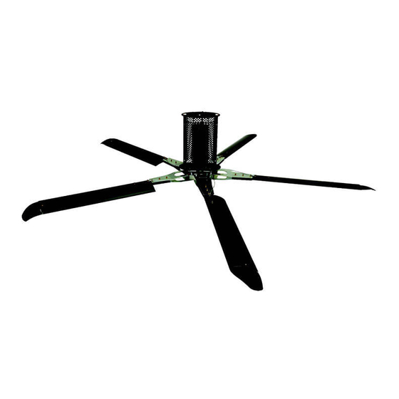
Industrial HVLS Fan
User's Manual
This manual applies to fans
manufactured beginning October
2017.
User's Manual
Do not install, operate or service this product unless you
have read and understand the Safety Practices, Warnings,
Installation, Operations,
and Installation and Operating Instructions contained in
Maintenance and Parts
this User's Manual. Failure to do so could result in death
or serious injury.
Part No. 6021140A
Advertisement
Table of Contents

Summary of Contents for Entrematic Industrial HVLS Fan
- Page 1 Industrial HVLS Fan User’s Manual This manual applies to fans manufactured beginning October 2017. User’s Manual Do not install, operate or service this product unless you have read and understand the Safety Practices, Warnings, Installation, Operations, and Installation and Operating Instructions contained in Maintenance and Parts this User’s Manual.
-
Page 2: Table Of Contents
Distributor Information ..........52 INTRODUCTION Welcome and thank you for choosing this industrial fan from Entrematic. This User’s Manual contains information that you need to safely install, operate and maintain the fan. It also contains a complete parts list and information about ordering replacement parts. Please keep and read this User’s Manual before using your new fan. -
Page 3: Safety Practices
DO NOT USE THE FAN IF IT APPEARS DAMAGED If you have problems or questions, contact your local OR DOES NOT OPERATE PROPERLY. Inform your distributor for assistance. supervisor immediately. October 2017 6021140A — Industrial HVLS Fans © Entrematic Group AB 2017... -
Page 4: Owner's Responsibilities
Modifications or alterations of industrial fans shall be made only with written permission of the original manufacturer. 6021140A — Industrial HVLS Fans October 2017 © Entrematic Group AB 2017... -
Page 5: Hardware
Secure tight 5/16 nut driver Cable clamp, safety cable Secure tight 1/2 nut driver NOTE: Motor cover fastener Secure tight 5/16 nut driver Additional spare hardware is provided as a courtesy. October 2017 6021140A — Industrial HVLS Fans © Entrematic Group AB 2017... -
Page 6: Fan Kit
3. Ensure all mounting hardware shown on page 5 is present. FOR OPTIONAL IFAN NETWORK FANS ONLY Ensure fan number matches network layout. Consult the round, network ID number label on shipping box. 6021140A — Industrial HVLS Fans October 2017 © Entrematic Group AB 2017... -
Page 7: Installation Considerations
HVAC systems, etc. In addition, OSHA requirements state that fan blades must be a minimum of 10' above the floor. October 2017 6021140A — Industrial HVLS Fans © Entrematic Group AB 2017... - Page 8 • Fans located below HVAC equipment must have a minimum clearance of greater than or equal to 2 fan diameters. See Fig. 3. Fig. 2 Greater than 1 fan dia. Fig. 3 Greater than 2 fan dia. 6021140A — Industrial HVLS Fans October 2017 © Entrematic Group AB 2017...
-
Page 9: Installation
1/4 fan diameter inside the fan blade arc. See Fig. 4. interference before operating fan. Fig. 4 Less than 1/4 fan dia. Greater than 1 fan dia. Greater than 1 fan dia. October 2017 6021140A — Industrial HVLS Fans © Entrematic Group AB 2017... - Page 10 (as measured from the end of the winglet) for A/C ducts mounted at or above the blade plane. 6021140A — Industrial HVLS Fans October 2017 © Entrematic Group AB 2017...
- Page 11 2. Install clamps. For thick flange I-beams add shims as required. Fasten using the supplied 1/2" dia x 2-1/2" Shim screws, lock nuts and washers. Torque to 44-48 ft-lbs. Building structure See Fig. 7. Clamp plate October 2017 6021140A — Industrial HVLS Fans © Entrematic Group AB 2017...
- Page 12 This will require additional hardware not included with the fan. Do not use strut channel clamps for any connections when mounting the fan. Consult a professional engineer or registered architect for specific mounting concerns. Fig. 10 6021140A — Industrial HVLS Fans October 2017 © Entrematic Group AB 2017...
- Page 13 If a mounting extension has been used, it may be necessary lock nut (x4) to obtain a longer cable from a local supplier. Fig. 13 Space cable clamps 6" apart Safety cable Motor frame October 2017 6021140A — Industrial HVLS Fans © Entrematic Group AB 2017...
- Page 14 Use a spirit level to verify powerhead unit hangs plumb. 5. Tighten pivot and angle adjustment bolts on fan mount. Torque to 44-48 ft-lbs. See Fig. 6. 6021140A — Industrial HVLS Fans October 2017 © Entrematic Group AB 2017...
- Page 15 1. Locate ventilation plug on gearbox. See Fig. 19. 2. Pull and remove plastic shipping brace and discard. 3. Remove orange brace removal note and discard. Plastic shipping seal Seal removal note October 2017 6021140A — Industrial HVLS Fans © Entrematic Group AB 2017...
- Page 16 Failure to do so could result in electrical shock, death or serious injury. STANDARD UNITS NOTE: Reference wiring diagrams on pages 35-39 for all field connections. 6021140A — Industrial HVLS Fans October 2017 © Entrematic Group AB 2017...
- Page 17 (blue) cable to the orange connector of the touch screen remote control. Excess blue cable length should WHT/GRN be neatly coiled and secured near VFD box. See Fig. 44 October 2017 6021140A — Industrial HVLS Fans © Entrematic Group AB 2017...
- Page 18 Train authorized personnel how to use the industrial fan using the operating procedures located on pages 21-27 in this manual. Fan size 24 FT Is the size displayed above correct? 6021140A — Industrial HVLS Fans October 2017 © Entrematic Group AB 2017...
- Page 19 60" above the floor and within 1000' of the fan touch screen remote. See Fig. 22 and wiring details on page 38. NOTE: FOR OPTIONAL NETWORKED UNITS, SEE SEPARATE MANUAL 6015948. October 2017 6021140A — Industrial HVLS Fans © Entrematic Group AB 2017...
-
Page 20: Components And Specifications
NEMA standard T.E.F.C., 2 HP, continuous duty three phase GEARBOX Double helical gear reduced, sealed lubrication. VFD unit Fig. 25 Safety cable Clamp Powerhead Universal mount Guy wires Motor cover Winglet Blade 6021140A — Industrial HVLS Fans October 2017 © Entrematic Group AB 2017... -
Page 21: Operating Instructions
OPERATING INSTRUCTIONS Fig. 26 FAN CONTROL SCREEN RPM increase Fan diameter Software version Start/Stop Forward Reverse RPM decrease Diagnostic screen Communication status (Green - Comm) (Black - No Comm) October 2017 6021140A — Industrial HVLS Fans © Entrematic Group AB 2017... - Page 22 Service Provider information. Contact this provider for all fan service issues. Fan Information: VFD serial number Motor Speed (x10) Motor Current (x10) Fire Alarm Input (green = enabled, red = disabled) Password Protection 6021140A — Industrial HVLS Fans October 2017 © Entrematic Group AB 2017...
- Page 23 197 Inrush current limit circuit fault 64 Heatsink Overheat 82 Input phase loss 199 Analog input fault 96 Stall prevention 201 Safety circuit fault 112 Brake transistor alarm 245 CPU fault October 2017 6021140A — Industrial HVLS Fans © Entrematic Group AB 2017...
- Page 24 2. Press the Update Password button. See Fig. 30. NOTE: When the password is enabled, the unit will automatically log out after 2 minutes. To return to diagnostic screen, select green return arrow. 6021140A — Industrial HVLS Fans October 2017 © Entrematic Group AB 2017...
- Page 25 Fig. 32 6. The user can select between fahrenheit and celsius units by checking or unchecking the celsius check box. See Fig. 32. October 2017 6021140A — Industrial HVLS Fans © Entrematic Group AB 2017...
- Page 26 Then click Fig. 34 on the Fan# on the bottom of the screen to go to the next Fan number and set the fan size for next fan. 6021140A — Industrial HVLS Fans October 2017 © Entrematic Group AB 2017...
- Page 27 3. Depending on the Fan Quantity that was set. The Fan# can be cycled through from 1 to the set fan quantity and then ALL which allows user to control all fans at one time. October 2017 6021140A — Industrial HVLS Fans © Entrematic Group AB 2017...
-
Page 28: Planned Maintenance
1. Inspect control panel for loose connections. Tighten as not use harsh cleansers. required. Legend Fig. 36 Symbol Description Cleaning (Location - Frequency) Visually Inspect (Replace Damaged Or Worn) Blow with Compressed Air (Location - Frequency) 6021140A — Industrial HVLS Fans October 2017 © Entrematic Group AB 2017... -
Page 29: Troubleshooting Guide
Blades bolts not properly a) Loosen the the blade nuts. Support the tick increases with speed. tightened. blade level (horizontally) before torquing the bolts to 24-28 ft-lbs. October 2017 6021140A — Industrial HVLS Fans © Entrematic Group AB 2017... -
Page 30: Vfd Fault Codes
Regenerative overvoltage E.OV1 E.AIE Analog input fault trip during acceleration Regenerative overvoltage E.SAF Safety circuit fault E.OV2 trip during constant speed Regenerative overvoltage E.OV3 trip during deceleration or stop 6021140A — Industrial HVLS Fans October 2017 © Entrematic Group AB 2017... - Page 31 Regenerative overvoltage E.OV1 E.AIE Analog input fault trip during acceleration Regenerative overvoltage E.SAF Safety circuit fault E.OV2 trip during constant speed Regenerative overvoltage E.OV3 trip during deceleration or stop October 2017 6021140A — Industrial HVLS Fans © Entrematic Group AB 2017...
-
Page 32: Fire Control System Fan Shutdown
If the jumper is left installed the fan will not shut down due to fire control system contacts. Customer supplied fire alarm dry contacts NC (contacts open on alarm) 6021140A — Industrial HVLS Fans October 2017 © Entrematic Group AB 2017... - Page 33 VFD box and fan. Be certain power is off when wiring to the control box. Failure to do so could result in electrical shock, death or serious injury. October 2017 6021140A — Industrial HVLS Fans © Entrematic Group AB 2017...
- Page 34 FIRE CONTROL SYSTEM FAN SHUTDOWN — OPTIONAL, continued Fig. 42 FIRE CONTROL SYSTEM FAN SHUTDOWN PANEL — NETWORK INSTALLATION (6020547) DELTA 6021140A — Industrial HVLS Fans October 2017 © Entrematic Group AB 2017...
-
Page 35: Electrical Schematics
VFD box and fan. Be certain power is off when wiring to the control box. Failure to do so could result in electrical shock, death or serious injury. October 2017 6021140A — Industrial HVLS Fans © Entrematic Group AB 2017... - Page 36 460V/60HZ 460V/60HZ LINE REACTOR 6010719 6010718 6010720 6010718 6010719 601718 200 230/3PH 360 480/3PH 200 230/3PH 360 480/3PH 360 480/3PH 360 480/3PH 2HP/1.5KW/7.0A 2HP/1.5KW/3.6A 2HP/1.5KW/7.0A 2HP/1.5KW/3.6A 3HP/1.5KW/5A 3HP/.75KW/5A 6021140A — Industrial HVLS Fans October 2017 © Entrematic Group AB 2017...
- Page 37 ELECTRICAL SCHEMATICS, continued Fig. 45 VARIABLE FREQUENCY DRIVE I/O October 2017 6021140A — Industrial HVLS Fans © Entrematic Group AB 2017...
- Page 38 TEMP CONTROL WIRING DETAILS — OPTIONAL Fig. 46 6021140A — Industrial HVLS Fans October 2017 © Entrematic Group AB 2017...
- Page 39 MULTI FAN WIRING DETAILS — OPTIONAL Fig. 47 6020547 6020547 DATA + DATA - F.G. October 2017 6021140A — Industrial HVLS Fans © Entrematic Group AB 2017...
- Page 40 2. Route supply power from the building source to the step down transformer. 3. Follow VFD installation instructions on page 17 using power from step down transformer (6017277) as the power source. Fig. 48 6021140A — Industrial HVLS Fans October 2017 © Entrematic Group AB 2017...
-
Page 41: Parts List
4Front Engineered Solutions could result in product ® malfunction, breakdown, premature wear, death or serious injury. Laminated wood beam shown for clarification October 2017 6021140A — Industrial HVLS Fans © Entrematic Group AB 2017... - Page 42 PARTS LIST — FAN, continued Fig. 50 6021140A — Industrial HVLS Fans October 2017 © Entrematic Group AB 2017...
- Page 43 GUY WIRE KIT - 9FT, 10FT EXT 6015678 SECONDARY STRAP TIE, BALL LOCK 6015265 1/8" WIRE CABLE CLAMP 6010900 NOTE: For corrosion resistant or explosion proof fans, consult factory for parts. October 2017 6021140A — Industrial HVLS Fans © Entrematic Group AB 2017...
- Page 44 16' CLEAR BLADE ASSY 6020516 18' CLEAR BLADE ASSY 6020517 20' CLEAR BLADE ASSY 6020518 22' CLEAR BLADE ASSY 6020519 24' CLEAR BLADE ASSY 6020520 FAN COVER FASTENERS 215702 6021140A — Industrial HVLS Fans October 2017 © Entrematic Group AB 2017...
- Page 45 PARTS LIST — VFD BOX Fig. 51 October 2017 6021140A — Industrial HVLS Fans © Entrematic Group AB 2017...
- Page 46 LINE REACTOR, 600V, 4.8A 6010719 MISTUBISHI VFD, 230V, 3PH, 2HP 6014907 FUSE 10A, 600V, KTK-R-10 6014015 ROTARY DISCONNECT 6015597 DISCONNECT SHAFT 150MM 6015599 DISCONNECT HANDLE 6015598 VFD CONTROL BOX ASSY 6021101 6021140A — Industrial HVLS Fans October 2017 © Entrematic Group AB 2017...
- Page 47 LINE REACTOR, 600V, 3.4A 6010718 MISTUBISHI VFD, 480V, 3PH, 2HP 6014909 FUSE 5A, 600V, KTK-R-5 6011797 ROTARY DISCONNECT 6015597 DISCONNECT SHAFT 150MM 6015599 DISCONNECT HANDLE 6015598 VFD CONTROL BOX ASSY 6021105 October 2017 6021140A — Industrial HVLS Fans © Entrematic Group AB 2017...
- Page 48 LINE REACTOR, 600V, 4.8A 6010719 MISTUBISHI VFD, 480V, 3PH, 3HP 6016452 FUSE 10A, 600V, KTK-R-10 6014015 ROTARY DISCONNECT 6015597 DISCONNECT SHAFT 150MM 6015599 DISCONNECT HANDLE 6015598 VFD CONTROL BOX ASSY 6021106 6021140A — Industrial HVLS Fans October 2017 © Entrematic Group AB 2017...
- Page 49 6018650 TOUCH SCREEN CONTROLLER — MULTI FAN REMOTE, KELLEY 6016943 TOUCH SCREEN CONTROLLER — MULTI FAN REMOTE, SERCO 6016944 TOUCH SCREEN CONTROLLER — MULTI FAN REMOTE, ENTREMATIC 6018649 J-BOX , PLASTIC, IVORY 6015648 CABLE CAT5, 100' W/ FERRULE (BLUE) 6015651...
- Page 50 PARTS LIST — TEMP CONTROL (OPTIONAL) Fig. 53 Item Quantity Part Description Part Number TEMP CONTROL ASSEMBLY 6013862 PHILIPS HEAD SCREW (NOT SHOWN) 6013543 4X2 STEEL J-BOX 6013415 MODBUS TEMP/IO CONTROL 6013861 6021140A — Industrial HVLS Fans October 2017 © Entrematic Group AB 2017...
-
Page 51: Warranty Information
WARRANTY THIS LIMITED WARRANTY IS 4FRONT’S (DBA ENTREMATIC) SOLE AND EXCLUSIVE WARRANTY WITH RESPECT TO THE HVLS FAN AND IS IN LIEU OF ANY OTHER GUARANTEES OR WARRANTIES, EXPRESS OR IMPLIED. THIS LIMITED WARRANTY APPLIES ONLY TO THE ORIGINAL PURCHASER OF THE HVLS FAN AND CANNOT BE TRANSFERRED. -
Page 52: Distributor Information
Please direct questions about your fan to your local distributor. Corporate Office: Your local distributor is: 1612 Hutton Dr. Suite 140 Carrollton, TX. 75006 Tel. (972) 466-0707 Fax (972) 323-2661 4Front Engineered Solutions ® © Entrematic Group AB 2017 Part No. 6021140A...
Need help?
Do you have a question about the Industrial HVLS Fan and is the answer not in the manual?
Questions and answers
What does fault code 82 mean?