Table of Contents
Advertisement
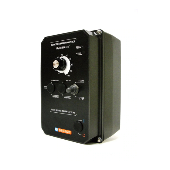
Installation & Operation Manual
Adjustable Frequency Drives for 3-Phase AC Motors
with Electronic Motor Overload Protection for Inverter Duty Motors
Washdown and Watertight for Indoor and Outdoor Use
3-Phase & PSC
Operates from 115, 208/230 Volt and 400/460 Volt 50/60 Hz AC Line
See Safety Warning,
on page 5.
The information contained in this manual is intended to be accurate. However, the manufacturer retains
the right to make changes in design which may not be included herein.
Notes: 1. UL approved as an electronic overload protector for motors. 2. Special software is available – contact
our Sales Department. 3. Do not use this drive with GFCIs. 4. Installation of a CE approved RFI filter is required.
KBAC SERIES
Variable Speed / Soft-Start AC Motor Drive
Rated for 208 – 230 and 400/460 Volt 50 & 60 Hz
2
AC Induction Motors from Subfractional thru 5 HP
This Manual Covers Models KBAC-24D, 27D, 29, 45, 48
NEMA-4X / IP-65
NOTE: THE DRIVE IS FACTORY SET FOR
4
60 Hz MOTORS. FOR 50 Hz MOTORS,
SEE SECTION 6.4, ON PAGE 17.
1
2,3
© 2008 KB Electronics, Inc.
(see back cover)
Advertisement
Table of Contents

Related Manuals for KB Genesis KBAC-24D

Summary of Contents for KB Genesis KBAC-24D
- Page 1 3-Phase & PSC AC Induction Motors from Subfractional thru 5 HP Operates from 115, 208/230 Volt and 400/460 Volt 50/60 Hz AC Line This Manual Covers Models KBAC-24D, 27D, 29, 45, 48 NOTE: THE DRIVE IS FACTORY SET FOR See Safety Warning, 60 Hz MOTORS.
-
Page 2: Table Of Contents
15 Run/Fault Relay Output Contacts Connection ..........16 16 Models KBAC-24D, 27D AC Line Input Voltage Selection (Jumper J1) ......16 17 Removing Jumper J1 on Models KBAC-24D, 27D . - Page 3 Items Included In this Package: Adjustable Frequency Drive, Installation and Operation Manual, Trimpot Adjustment Tool, CE Approved Product Information Card, Warranty Registration Card. Drive Model Nos. and Part Nos. Part No. Model No. Black White* KBAC-24D 9987 9988 KBAC-27D 9520 9521 KBAC-29 9528...
-
Page 4: Quick-Start Instructions
Note: The rated AC line voltage of the drive must match the actual AC line input voltage. On Models KBAC-24D, 27D, the setting of Jumper J1 must match the AC line input voltage. Models KBAC-24D, 27D: Designed to accept single-phase (Terminals “L1”, “L2”) AC line input only. -
Page 5: Safety Warning
Models KBAC-45, 48: Designed to accept 3-phase (Terminals “L1”, “L2”, “L3”) AC line input only. Rated for 400/460 Volt AC line input only. See Figure 8, on page 14. AC LINE FUSING – It is recommended that a fuse(s) or circuit breaker be installed in the AC line. Fuse each conductor that is not at ground potential. -
Page 6: Introduction
This product complies with all CE directives pertinent at the time of manufacture. Contact our Sales Department for Declaration of Conformity. Installation of a CE approved RFI filter is required. See RFI Filters & Chokes Selection Guide D-321 (Part No. A42027) for selection of filters to meet the Industrial or Residential Standard. - Page 7 • Start/Stop Switch – Provides electronic start and stop functions. • Barrier Terminal Block – Facilitates wiring of motor, AC line, and Run/Fault Relay Output Contacts. • Jumper Selection of Drive Output Frequency – Increases the motor speed up to two times the rated RPM.
-
Page 8: Jumper Selectable Features
TABLE 1 – JUMPER SELECTABLE FEATURES PC Board Description Designation KBAC-24D KBAC-27D KBAC-29 KBAC-45 KBAC-48 AC Line Input Voltage (115, 230) — — — Motor Horsepower (see Table 4 - Electrical Ratings, on page 10) Automatic Ride-Through or Manual Restart (A*, M) -
Page 10: General Performance Specifications
KBAC-48 Notes: 1. White FDA approved finish. 2. Bold indicates factory setting. Jumper J2 on Model KBAC-24D is labeled “1”, “3/4”, “1/2”, “1/4”, “1/8” (facto- ry set to the “1” position). Jumper J2 on Model KBAC-27D is labeled “2”, “1 ⁄... -
Page 12: Important Application Information
IMPORTANT APPLICATION INFORMATION MOTOR WITH EXTERNAL FAN COOLING – Most totally enclosed fan-cooled (TEFC) and open ven- tilated 3-phase AC induction motors will overheat if used beyond a limited speed range at full torque. Therefore, it is necessary to reduce motor load as speed is decreased. Note: Some fan-cooled motors can be used over a wider speed range. -
Page 13: Wiring Instructions
To maintain the watertight integrity of the drive, be sure to use suitable watertight connectors and wiring which are appropriate for the application. Model KBAC-24D contains two mounting holes for standard 1/2” liquidtight fittings (not supplied) (one watertight plug is provided, if only one knockout is used). -
Page 14: Models Kbac-29, 45, 48 Ac Line Input, Motor, And Ground Connections
FIGURE 8 – MODELS KBAC-29*, 45, 48 AC LINE INPUT, MOTOR, AND GROUND CONNECTIONS Model KBAC-29 Only Wire the single-phase AC line input to Terminals "L1", "L2", as shown below. MOTOR AC LINE AC LINE 208/230, 400/460 Volt 208/230 Volt Motor 3-Phase, 50/60 Hz Ground (Earth) -
Page 15: Remote Start/Stop Switch Connection With Normally Open Stop Contact
inside the drive. The switch assembly may be FIGURE 10 – REMOTE START/STOP SWITCH CONNECTION removed if a liquidtight seal is used to cover WITH NORMALLY OPEN STOP CONTACT the hole in the front cover. After applying (J9 Installed in “NO” Position) power to the drive, momentarily set the Start/Stop switch to the “START”... -
Page 16: Setting Selectable Jumpers
*Run Mode or Stop Mode is selected using the Start/Stop Switch. **Overload, I t, Short Circuit, Undervoltage, Overvoltage. SETTING SELECTABLE JUMPERS FIGURE 16 – MODELS KBAC-24D*, 27D AC LINE INPUT VOLTAGE SELECTION The drive has customer selectable 208/230 Volt AC Line Input... -
Page 17: Removing Jumper J1 On Models Kbac-24D, 27D
Start/Stop Switch. See Figure 19. Also see Section 11.2, on page 22, for the Status (ST) LED indication. *On Model KBAC-24D, Jumper J3 is labeled “AUTO” and “MAN”. 60 Hz AND 50 Hz MOTOR FIGURE 18 –... -
Page 18: Available Torque Vs. Output Frequency
BOOST MODE SELECTION (J6) – FIGURE 21 – AVAILABLE TORQUE . OUTPUT FREQUENCY Jumper J6 is factory set to the “FIX” position for Fixed Boost. For Adjustable Boost using the BOOST Trimpot, set Jumper J6 to the “ADJ” position. See Figure 23. Also see Section 12.8, on pages 24 –... -
Page 19: Mounting Instructions
MOUNTING INSTRUCTIONS FIGURE 25 – “RUN” OR “FAULT” It is recommended that the drive be mounted OUTPUT RELAY OPERATION SELECTION vertically on a flat surface with adequate “Run” Output Relay Operation ventilation. Leave enough room below the (Factory Setting) “Fault” Output Relay Operation (J8 Installed in “R”... -
Page 21: Drive Operation
DRIVE OPERATION START-UP PROCEDURE – After the drive has been properly setup (jumpers and trimpots set to the desired positions) and wiring completed, the start-up procedure can begin. If the AC power has been properly brought to the drive, the power (PWR) LED will illuminate green. The status (ST) LED will indicate drive status, as described in Section 11.2. -
Page 22: Trimpot Adjustments
the user that all drive and microcontroller operating parameters are normal. Table 7, summarizes the “ST” LED functions. TABLE 7 – DRIVE OPERATING CONDITION AND STATUS LED INDICATOR Drive Operating Condition Flash Rate and LED Color Normal Operation Slow Flash Green Overload (120% –... - Page 23 3 seconds with the trimpot fully clockwise and 25% of full drive output voltage for 1 second with the trimpot fully counterclockwise. Models KBAC-24D, 27D, 29 are factory set for COMP 49 Volts for 1.2 seconds and Models KBAC-45, 48 are factory set (Shown Factory Set to 1.5 Volts/Hz)
- Page 24 12.7 MOTOR OVERLOAD (I t) WITH RMS CURRENT LIMIT (CL)* – Sets the current limit (overload), which limits the maximum current to the motor, which prevents motor burnout and eliminates nui- sance trips. The CL Trimpot is factory set to 160% of the drive rated current. To increase the current limit, rotate the CL Trimpot clockwise.
-
Page 25: Run-Stop-Jog Switch Connection
WARNING! To avoid motor winding overheating and failure, FIGURE 38 – BOOST TRIMPOT RANGE do not overboost the motor. Note: An unloaded motor with excessive boost will draw more current than a partially loaded motor. The boost voltage may be adjusted as follows: 1. - Page 26 – NOTES –...
- Page 27 – NOTES –...
-
Page 28: Limited Warranty
LIMITED WARRANTY For a period of 18 months from the date of original purchase, KB Electronics, Inc. will repair or replace without charge, devices which our examination proves to be defective in material or workmanship. This warranty is valid if the unit has not been tampered with by unauthorized persons, misused, abused, or improperly installed and has been used in accordance with the instructions and/or ratings supplied.
Need help?
Do you have a question about the KBAC-24D and is the answer not in the manual?
Questions and answers