
Subscribe to Our Youtube Channel
Summary of Contents for KaVo EWL 4452
- Page 1 Operating Instructions Frequency inverter type EWL 4452 KaVo Elektrotechnisches Werk GmbH Wangener Straße 78 D-88299 Leutkirch Tel.: 0 7561 / 86-0 • Fax: 0 7561 / 86-371...
-
Page 3: Table Of Contents
Table of contents A 1 User information ..........2 A 1.1 Meaning of the pictograms . -
Page 4: A 1 User Information
Repair and maintenance work - except for the activities described in this User Manual - may be performed only by qualified specialists. In the event of modifications by third parties, the approvals shall become null and void. KaVo recommends using only original spare parts for operation and for repair. -
Page 5: A 1.3 Precautions
User information A 1.3 Precautions Safe operation and protection of the device is ensured only by proper use, in accordance with the User Manual, with the tools approved for this purpose. The following should also be observed: • the work safety regulations, •... -
Page 6: A 1.4 Purpose And Potential Applications
The control and monitoring of the inverter are performed by several microprocessors. This ensures high reliabili- ty and flexibility. A firmware update can be performed on a PC via a serial interface (RS232); contact KaVo-EWL in this context. The inverter can be completely remote-controlled. Various inputs and outputs are freely programmable. -
Page 7: A 1.5 Technical Data
User information A 1.5 Technical data Operation Menu-controlled with plain text display with two lines of 16 characters each, four keys for menu control, one start key, one stop key, indicator lamps for operation (green), overload (yel- low), fault (red) and start (green). All inverter parameters can be input and changed on the control panel. - Page 8 User information Remote control The function of the programmable inputs and outputs is described under Description of function A 4.4. Digital control inputs FB_IN1 ... 6 opto-decoupled, Re = 10 kΩ, unwired=low U_low = 0...+5 V, U_high = +13...+35V, Ie = 2.4 mA at 24 V Input protected up to max.
-
Page 9: A 2 Scope Of Delivery - Accessories
Scope of delivery - Accessories A 2 Scope of delivery - Accessories A 2.1 Scope of delivery • Frequency inverter type 4452 Mat. No. 0.641.7700 • Mounting plate for mounting switch cabinet (mounted on the inverter) • Instructions for use and assembly •... -
Page 10: A 3 Controls
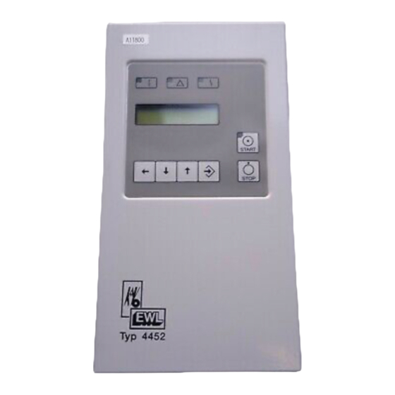
Controls A 3 Controls LED Betrieb/ LED Warnung/ LED Störung/ Operation Warning Fault grün/green gelb/yellow rot/red LCD-Anzeige/ LCD-display LED Start 16 Zeichen x 2 Zeilen grün/green 16 characters x 2 lines START Start STOP S12 S11 S10 Abbruch, unten/ oben/ Enter, Eingabe Stop Weiterschaltung/ down... -
Page 11: A 3.1 Rating Plate
Controls A 3.1 Rating plate Hersteller/ Gerätetyp/ manufacturer Device type Seriennummer/ KaVo ELEKTROTECHNISCHES WERK GMBH Serial number D-88299 Leutkirch im Allgäu Max. mögl. Gerät-Ver- Warnhinweis: sorgungsspannung (diese S-No. Begleitpapiere Angabe ist länder- beachten/ Type EWL 4452 spezifisch und kann von Warning: No. -
Page 12: A 4 Description Of Functions
Description of functions A 4 Description of functions The max. output frequency is 3000 Hz (180 000 min ) for ASM motors and 2000 Hz for DC motors. The max. output power is 2.5 kVA. The frequency inverter type 4452 is suitable for the variable-frequency control of various motors, especially with high frequencies of up to 3 kHz, corresponding to 180,000 min . - Page 13 Description of functions 2 auxiliary voltages +24 V (max. 80 mA) for wiring of the digital inputs IN1...IN6 and of the relay outputs REL1...REL4 +10 V (max. 15 mA) as auxiliary supply from external potentiometers to the analogue inputs AIN1 and AIN2 The function of the outputs (4 relay and 2 analogue outputs) is predetermined directly by the corresponding parameters.
- Page 14 Description of functions Umrichter 4452 / Inverter 4452 Fernbedienung / remote control D-Sub 25 FB+10V FB-AIN1 FB-AIN2 FB-AOUT1 FB-AOUT2 FB-AGND FB-IN1 FB-IN2 FB-IN3 FB-IN4 FB-IN5 FB-IN6 FB-C-IN FB-GND FB+24V FB-C-REL FB-REL1 FB-REL2 FB-REL3 FB-REL4-OE FB-REL4-S FB-OUT-FREQ Ansteuerung mit Fremdspannung Control with external voltage...
-
Page 15: A 4.5 Motor Code
The frequency inverter type 4452 can adapt automatically to up to 8 different motors via three code inputs at X7. The code inputs can be predetermined directly via the motor plug or by a superior control. externer Anschluß/ Umrichter Typ EWL 4452/ external connection Inverter type EWL 4452 X7.3... -
Page 16: A 4.6 Setpoint Value Selection
Description of functions A 4.6 Setpoint value selection The frequency setpoint value (speed setpoint value) can be predetermined by various sources, and the mode of operation is shown in the following figure. P7-Betriebsart P7-select func. Sollwert von Bedienpanel/ Setpoint value of control panel Panel P1-f_soll(rated) P10-f_soll_akt... -
Page 17: A 4.10 Block Diagram
Description of functions A 4.10 Block diagram RS232 9 pol. / 9 pin +7V-F TXD-F RXD-F FB+10V FB-AIN1 FB-AIN2 FB-AOUT1 FB-AOUT2 FB-AGND Bedieneinheit FB-GND control panel FB+24V FB-OUT-FREQ FB-IN1 FB-IN2 FB-IN3 FB-IN4 Bediensteuerung FB-IN5 panel control unit FB-IN6 FB-C-IN FB-REL1 FB-REL2 FB-REL3 FB-REL4-OE... -
Page 18: B 1 Assembly And Installation
Assembly/Installation B 1 Assembly and Installation Before the installation and commissioning of this device, please read the safety and warning information under Section A1 carefully. B 1.1 Assembly The frequency inverter type 4452 should be mounted as follows in the switch cabinet: Fasten the mounting plate to the back panel of the switch cabinet by means of four screws. -
Page 19: B 1.2 Electrical Installation
Assembly/Installation B 1.2 Electrical Installation When installing the inverter, the applicable safety regulations must be observed. Cut-out devices for preventing unexpected start-up must be provided. A device for the electrical isolation of the inverter must be provided unless a mains cable with a plug is used. The inverter must be provided with 16 A power cut-outs with tripping characteristic B. - Page 20 Assembly/Installation Connection of a KaVo spindle A KaVo spindle is connected according to the following table; on operation for the first time, check the direction of rotation specified on the spindle (arrow). Compliance with EMC guidelines is ensured only with the use of spindle types EMC 4060 – 4063 with shielded connecting cable.
- Page 21 Assembly/Installation X5: Connection of external control panel and PC (option) Plug type: 9-pole D-Sub jack X6: Connection of external brake resistance R-Brems/R-brake (20...650 Ohm, 150...1000W) Interner Bremswiderstand : Brücke zwischen Pin 2 und Pin 3 Internal brake resistance: bridge between pin 2 and pin 3! Externer Bremswiderstand : Brücke entfernen und R-Brems anschliessen External brake resistance: remove bridge and connect R-brake! Brückenstecker zur...
- Page 22 Assembly/Installation X7: Connection of the motor sensors This connection is used for the motor temperature sensor, motor coding, speed sensor in the case of the ASM motor and position sensors in the case of the BLDSC motor. PTC/KTY Motortemperatur/motor temperature +12V / max.
-
Page 23: B 2 Fast Commissioning, The Most Important Aspects In Brief
For special applications, the inverter can be preconfigured by KaVo before delivery. This is evident from the fact that the parameter sheet (last sheet of these instructions) has been completed and the inverter shows the stan-... -
Page 24: B 2.3 Setting Motor Parameters
Fast commissioning B 2.3 Setting motor parameters If you wish to set up the inverter for a KaVo spindle, call up the default parameters for the corresponding spindle: Special functions SP1- motor parameter factory setting KAVO Type xxxx Menu: Keys... -
Page 25: B 2.6 Reset
Fast commissioning After the inverter has been switched on (mains on), the device tests various hardware components. The standard display appears on the LCD display H1, and LED Operation H3 (green) lights up. If an error occurs, LED H5 (red) lights up, see Section B 4 Error messages. Meaning of the status displays: H3 - LED Operation (green) - The inverter is ready for operation, the motor can be started or is running, no fault is present. -
Page 26: B 3 Configuration
Configuration B 3 Configuration All inverter-relevant data are accessible in the form of parameters P1 ... P150. The configuration in turn is divided into Default parameters Superior parameters on which further settings are dependent (P1 .. P9) (speed setpoint value, display settings, operating language, mode...) Display values Pure display values which cannot be changed (P10 ... - Page 27 Store motor parameter for motor control and regulation P100 Motorparameter Werkseinstellung P136 motor parameter factory setting P150 KaVo Typ(e) xxxx (SP 142) Motorparameter für vordefinierte Spindeln Motor parameters for predefined spindles siehe/see KaVo automatische Speicherung autom. Laden bei Netz ein Kap./Sec.
-
Page 28: B 3.1 Commissioning Parameters, Examples
Configuration B 3.1 Commissioning parameters, examples In order to start from a defined initial state, the factory setting must first be restored, which can be achieved with Special functions SP3 - Reset parameter / Motor parameter the following menu option: "... -
Page 29: B 3.2 Examples Of Configuration
Configuration B 3.2 Examples of parameters ASM motor Speed range up to 60 000 min , 230V~, 5A~, cos phi 80 %, motor protection with PTC P90-motortype P91-f_mot_nom 1000 Hz P92-V_mot_nom 230 V P93-I_mot_nom P94-cos phi P96-no. of poles P85-motor prot. BLDC motor Speed range up to 60 000 min , 220V~ 5 A~ (max 8A~), no centrifugal mass, normal startup... - Page 30 Display 0=off, 1=on SP21 Test remote ctrl digital input D.IN 1 2 3 4 5 6 Display L=low, H=high SP143 Further spindles, if present SP142 Kavo type 4060 SP14 SP141 factory default factory setting SP13 SP100 delete memory M1 ... M8...
-
Page 31: B 3.4 Sp1 - Store And Recall Motor Parameters
Special functions - motor parameter - factory setting- KaVo type xxxx SP142 - With this function, the motor parameters P41 ... P96 are preset to values for specific KaVo spnidles. Depending on use and operating point, the corresponding parameters must be adapted. -
Page 32: B 3.6 Sp3 - Reset Parameter To Factory Default
(SP300) with the Enter key , the function is performed. Stored motor parameters in the memories M1 ... M6 are retained. B 3.7 SP4 - TKD test programs Various test programs for the KaVo Technical Customer Service are included under this menu option. -
Page 33: B 3.8 Parameter List
Configuration B 3.8 Parameter list This list includes all displayable and alterable parameters. In the column Change display, the following abbreviations are used: N = not alterable, S = alterable only when motor stationary, I = always alterable, even when motor running P90-motortype, M = display and alterability dependent on P3-param level... - Page 34 Configuration Par. Indication Description Value range, Unit Factory Change in display physical value setting display U/f characteristic (ASM motor) Startup voltage at f=0 , 1...50 I P M V_boost 3%V_nom 3%V_nom 1st characteristic point frequency , 30... 3000 I P M f_nom f_nom 1st characteristic point voltage...
-
Page 35: B 3.9 Description Of The Individual Parameters
Configuration B 3.9 Description of the individual parameters The square brackets [ ] behind the entries indicate the numerical value; this is displayed numerically in the oper- P5-Language ating language (see ). If a natural language (German, English ...) is chosen, the corresponding text appears instead. -
Page 36: B 3.11 Display Values
Configuration P7-Select func Selection of the source from which the inverter is to be operated with start/stop, setpoint speed value and torque limitation. The digital and analogue output values are always output independently of the setting. Panel Values: -Operation is via the control panel. The digital and analogue levels at the remote control X4 are not taken into account. - Page 37 Configuration P14-f_motor (display value) f_motor is the current motor frequency and differs from the inverter frequency (P13) only in the case of an P70-control ASM motor if the control ( ) is set to slip or speed control. In all other cases and for BLDC and P13-f_out_act BLDCS motors this parameter is the same as the output frequency ( P8-speed displ...
-
Page 38: B 3.12 Motor Operating Values
The value is read in from the EEPROM. P36-Inverter (display value) Inverter shows the inverter type (KaVo type 4452). P37-SW panel (display value) SW panel shows the software version and the date of the operating software. - Page 39 Configuration P44-I_limit [ASM, BLDC, BLDCS] Limitation of phase current for normal motor running. The inverter limits the output current to I_limit. P57-I_DC_stop P52-I_start The stop current ( ) and, in the case of the BLDC motor, the startup current ( are unaffected by this.
- Page 40 Configuration P51-t_start [-, BLDC, -] P53-f_start Startup time for microstep startup in BLDC motor from 0 Hz to P52-I_start a P53-f_start With t_start > 0.5 sec sind, must also be input. In the case of the microstep startup, the BLDC motor is operated as a synchronous motor with constant current P52-I_start P53-f_start ) .
- Page 41 Configuration P54-t_off [-, BLDC, -] Switch-off time of the inverter. In the microstep startup, the inverter is repeatedly switched off briefly in a cyclic manner in order to measure the e.m.f. voltage of the BLDC motor; this is used for detecting the position of the rotor at low speeds. In the case of larger inductances of the motor winding, longer times should be set.
- Page 42 Configuration P58-emerg. stop [ASM, BLDC, BLDCS] Parameter influences the behaviour on mains failure. Values: - At mains failure, the motor runs out freely and there is no braking. - The motor is braked with maximum power of the brake resistance as long as the inverter can still supply itself from the motor voltage.
- Page 43 Configuration P60-V_start [ASM, - -] U/F-characteristic: Startup voltage at frequency zero. P41-f_mot_min The minimum frequency to be output by the inverter is specified in , and the output voltage at this frequency is calculated using the U/F characteristics. 3%_V_nom Specific values - the startup voltage at f=0 is set internally to the value of 3% of the rated motor voltage from P92-V_mot_nom Minimum value:...
-
Page 44: B 3.13 Regulation
Configuration B 3.13 Control P70-control [ASM, -, -] Selection of the speed control for ASM motors U/f table Values: - Voltage control via U/f table, no rise -I*R-load-comp - I*R and load compensation, the motor voltage is adapted as a function of the load. The P71-I*R-factor P72-loadcomp P73-comp-t_filt... - Page 45 Configuration P75-slipkomp [ASM, -, -] In the case of asynchronous motors, the fact that the actual speed deviates from the nominal speed under load is disadvantageous and is caused by the motor slip. Depending on the dimensioning of the motor, the slip is up to 10% at nominal load.
-
Page 46: B 3.14 Monitoring
Configuration P81-N-contr-KP [ASM, BLDC, BLDCS] This parameter influences the control (PID) for the motor speed, it being possible to set the gain (proportional part) here. Minimum value: Maximum value: 500 % Factory setting: 50 % P82-N-contr-t_n [ASM, BLDC, BLDCS] This parameter influences the control (PID) for the motor speed, it being possible to set the reset time (integral part) here. -
Page 47: B 3.15 Nominal Motor Values
Configuration B 3.15 Nominal motor values In this section, the nominal data of the connected motor should be input. The nominal data are shown on the rating plate or the data sheet. P90-motortype [ASM, BLDC, BLDCS] Input of motor design. no motor Values: - no motor defined... -
Page 48: B 3.16 Device Parameters, Remote Control
Configuration B 3.16 Device parameters, remote control P100-R_ext_brake Resistance value of the external brake resistance at X6. P101-P_ext_brake The value of the external brake resistance must be in the range from 27 to 100 W, and should also be set for this purpose. The resistor should be connected to terminal X6.1-3 and the bridge at X6.2-3 should be removed. - Page 49 Configuration P110-input IN1 Function of the digital input IN1 Values: - Input has no function run/stop - U_high = run, U_low = stop - Pulse at U_high = run, after which the input can return to U_low, the inverter remaining in the started state.
- Page 50 Configuration P120-relay REL1 Output value of relay REL1 Values: - no function, relay is in opened state. operation - The inverter is ready for operation, the motor can be started. failure - The inverter is in the error state, the motor cannot be started and a reset is required. overload - The motor current has reached the current limit.
- Page 51 Configuration P130-analogue AIN1 Function of the analogue input 1 (AIN1) Werte: - Input has no function f_rated - The voltage present at AIN1 is used as the rated speed value. The frequency limit should be set P135-f_rem_min P136-f_rem_max for the input voltage V_e = 0V in and for V_e = 10V in Factory setting: P131- analogue AIN2...
- Page 52 Configuration P135-f_rem_min Minimum rated frequency for analogue rated frequency default AIN1 at V_e = 0V. This parameter is evaluated P130-analogue AIN1 only if is configured for rated frequency. P8-speed displ By means of parameter , this parameter can be changed from frequency display to speed P96-no.
-
Page 53: B 4 Error Messages
Error messages B 4 Error messages If a warning occurs, the warning LED H2 (yellow) lights up and the motor can continue running. If an error is detected, the fault LED H5 (red) lights up and the motor is stopped. The following is applicable for both types of error: If the configuration mode or the special functions mode is active, the error number is shown in the LCD display only on entry into the normal state. -
Page 54: B 4.2 Error On Motor Control, Can Be Influenced By Operator
Error messages B 4.2 Errors on motor control, can be influenced by operator 1 Current limitation active - warning 2 Motor temperature too high 3 Inverter cooler temperature too high 4 Motor current too high, inverter limit exceeded 5 Motor current in generator mode too high, inverter limit exceeded 6 Inverter intermediate circuit voltage V_WR too high 7 Mains input voltage too low 8 Mains input voltage too high... -
Page 55: B 4.6 Description Of All Errors And Warnings
Error messages B 4.6 Description of all errors and warnings W = Warning message, inverter still ready for operation E= Error message, serious fault, inverter not ready for operation, a reset must be triggered No. Description Cause Rectification 1 W Warning. Motor current has Motor too highly loaded, rise time Reduce load, adapt parameter P46-t_rise... - Page 56 Error messages Description Cause Rectification 15 W No motor defined. Parameter set to Set parameter P90-motortype P90-motortype “no motor”. presumably the inverter is still not configured, see Section B 2 Fast commissioning. 16 E Motor earth fault detected Earth fault in motor or in supply cable Check motor and supply cable.
- Page 57 Error messages Description Cause Rectification 43 W Automatic test on switching on, EEPROM on motor control circuit bo- If the error persists in spite of re- data memory of motor circuit ard faulty peatedly switching on and off, a board hardware error is present and the inverter should be sent for repair.
- Page 58 Send inverter for repair or request of motor control circuit board circuit board faulty the flash programming software from KaVo. 66 E Software versions of control Internal communication of control Send inverter for repair or request circuit board and of motor...
-
Page 59: Declaration Of Conformity
Conformity Statement KaVo ELEKTROTECHNISCHES WERK Vertriebsgesellschaft m.b.H. Wangener Str. 78 D-88299 Leutkirch im Allgäu declare that the product frequency inverter type 4452 -to which this declaration relates complies with the essential safety requirements in accordance with the provisions of the Directive(s) -
Page 60: Index
Rating plate........9 Apparent motor current ....35 maximum........36 Real motor current......35 ASM motor......3,26,27 minimum ........36 REL1...REL4 ......48 Assembly ........16 Relay...........48 KaVo spindle ......22 Remote control parameters..22 Basic parameters..22,24,26,31,33 KTY..........44 Remote control ..6,10,18,28,46 Basic state....21,26,27,30 Reset ......23,35,51,52 BLDC motor.......3,26,27 Language ........33 Rise time........37 BLDCS motor ....3,26,27... -
Page 62: Customer Settings
Customer setting Inverter 4452 motor parameters Customer: Date: Motor/spindle: Official responsible: Remark : Sett.- Description Display Unit Factory Customer Prio. P ASM BLDC BLDCS setting setting Special settings Min. motor frequency f_mot_min Max. motor frequency f_mot_nom f_mot_max Max. motor voltage U_mot_nom V_mot_max Current limit...
Need help?
Do you have a question about the EWL 4452 and is the answer not in the manual?
Questions and answers