
Summary of Contents for Sutron XLink 500
- Page 1 XLink 2 Generation Models: XLink 500, XLink 100 Operations & Maintenance Manual Part No. 8800-1217 Rev 8.21.1 August 28, 2018...
-
Page 2: Table Of Contents
XLINK-500 and XLINK-100 Left Terminal strip ..................17 3.9. XLINK-500 Right Terminal Strip ......................18 4. Installing XLink .............................. 19 4.1. Attaching XLink 500 and 100 ........................19 4.2. Installing Option Cards ........................... 20 4.3. Earth Ground Point ..........................22 4.4. - Page 3 XLINK 500/100 Operations & Maintenance Manual page # 3 4.14. Connecting mV Sensors .......................... 30 4.15. Connecting Thermistors ......................... 30 4.16. Connecting Thermocouples ........................32 4.17. Connecting Strain Gauges ........................34 4.18. Programmable Excitation References ....................34 4.19. Connecting Prop/Vane or Anemometer/Vane Wind Sensors ..............34 4.20.
- Page 4 XLINK 500/100 Operations & Maintenance Manual page # 4 6. Operating XLink ............................62 6.1. Creating a New Station in LinkComm ..................... 62 6.2. Connecting to a station in Your Station List ................... 62 6.3. Importing Setups From Another User Or Station ................... 62 6.4.
- Page 5 XLINK 500/100 Operations & Maintenance Manual page # 5 9.9. Measurement Setup Defaults ......................101 9.10. Measurement Calibration ........................101 9.11. Multiple Measurements Using the Same Sensor ................. 101 10. Telemetry Setup ............................103 10.2. Cell Setup ............................. 105 10.3. Iridium Setup ............................109 10.4.
- Page 6 XLINK 500/100 Operations & Maintenance Manual page # 6 14.3. System Errors ............................137 15. Transmission Data Formats ......................... 139 15.1. Pseudobinary B Data Format ....................... 139 15.2. Pseudobinary C Data Format ....................... 141 15.3. Pseudobinary D Data Format ....................... 143 15.4.
- Page 7 19.3. Script Tasks ............................184 19.4. Scripts Management ..........................186 20. Appendix A – Specifications ........................188 21. Appendix B – Sutron Customer Service Policy ..................... 190 22. Appendix C – Commercial Warranty ......................191 22.1. Sutron Manufactured Equipment ......................191 22.2.
-
Page 8: Scope Of Supply
XLINK 500/100 Operations & Maintenance Manual page # 8 1. Scope of Supply Site controller with the ability to collect, record, and transmit sensor data. Includes the following: XLink 100 Power supply connection Earth ground connection Solar panel connection ... - Page 9 XLINK 100, Verizon LTE, NEMA-4 box, internal antenna XLINK100-C1-1E XLINK 100, Verizon LTE, NEMA-4 box, external antenna XLINK500-C1-1 XLINK 500, Verizon LTE XLINK500-C1-1C XLINK 500, Verizon LTE, NEMA-4 box, internal antenna XLINK500-C1-1E XLINK 500, Verizon LTE, NEMA-4 box, external antenna Iridium XLINK100-IR-1 XLINK 100, IRIDIUM...
- Page 10 XLINK 500/100 Operations & Maintenance Manual page # 10 CELLULAR-MOD-5 HSPA telemetry pluggable modem card OTHER 8111-1113-1 Externally mounted RF coaxial lightning arrestor to be used on a NEMA-4 enclosure variant (3 ft type N male – N male cable included)
-
Page 11: General Safety Information
Before connecting the power supply, check that all wires are properly attached to the screw terminal strips. Do not open unit. There are no user serviceable parts inside. Have a defective unit checked and repaired by the Sutron repair center. Do not attempt to repair units yourself. Symbol Description Direct current. -
Page 12: Introduction
# 12 3. Introduction Sutron’s XLink products are site controllers with optional built-in modems. These products are designed to collect, store, and transmit sensor data. The devices have been designed for hydrometry, meteorology, and environmental monitoring. Two models are available: XLink 500 and XLink 100. -
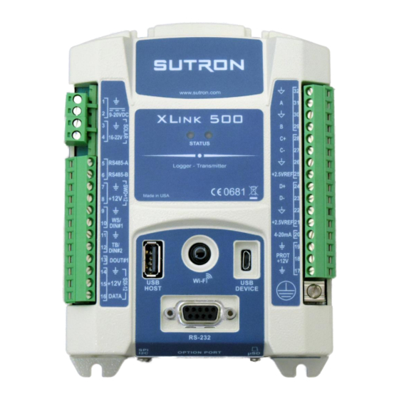
Page 13: Xlink 500
XLINK 500/100 Operations & Maintenance Manual page # 13 3.1. XLink 500 The figure below shows the connections provided by the XLink 500: Power/Battery 1 terminal block Solar Panel input Status LED Wi-Fi button 1 terminal block USB to PC... -
Page 14: Xlink 100
XLINK 500/100 Operations & Maintenance Manual page # 14 3.2. XLink 100 The figure below shows the connections provided by the XLink 100. Power/Battery Status LED Wi-Fi button 1 terminal block USB to PC USB Host Earth Ground RS232 to PC... -
Page 15: Multi-Function Button
XLINK 500/100 Operations & Maintenance Manual page # 15 3.3. Multi-function Button There is a multi-function button installed on the front. Briefly pressing this button will turn on the Wi-Fi. The multi-function button may be used to reboot the unit. If the button is held down for 5 seconds, the red LED will come on. -
Page 16: Usb Micro (Otg)
XLINK 500/100 Operations & Maintenance Manual page # 16 Python scripts may use the RS232 port in order to drive displays, send data to modems, or communicate with other devices. 3.6. USB Micro (OTG) The USB OTG port is the primary port for connecting to a PC. The USB port is a micro-B and compatible with a standard micro-B to Type A male USB cable that works with most PC’s. -
Page 17: Xlink-500 And Xlink-100 Left Terminal Strip
XLINK 500/100 Operations & Maintenance Manual page # 17 3.8. XLINK-500 and XLINK-100 Left Terminal strip XLINK-500 has two terminal strips to provide the connections for sensors and outputs. XLINK-100 has only one terminal strip on left side. The table below describes the purpose of each connection on the left terminal strip for XLINK-... -
Page 18: Xlink-500 Right Terminal Strip
XLINK 500/100 Operations & Maintenance Manual page # 18 3.9. XLINK-500 Right Terminal Strip The table below describes the purpose of each connection on the right terminal strip on XLINK- 500. No connections except for Earth Ground are available on XLINK-100... -
Page 19: Installing Xlink
XLINK 500/100 Operations & Maintenance Manual page # 19 4. Installing XLink 4.1. Attaching XLink 500 and 100 Requirements of the intended installation site are: Sufficient protection from moisture for an IP 41 device. Proper space for the electrical cables ... -
Page 20: Installing Option Cards
XLINK 500/100 Operations & Maintenance Manual page # 20 4.2. Installing Option Cards An XLink may be ordered with either a Cell or Iridium card from the factory which will be preinstalled into the unit. If you choose to change the card in your unit, you will need to do the following. - Page 21 XLINK 500/100 Operations & Maintenance Manual page # 21 4. Slide the option card into the open port. You may need to unscrew the 2 screws on the option card a little to allow the card to slide into the slot fully. Note that the orientation of the option card always has the text right side.
-
Page 22: Earth Ground Point
XLINK 500/100 Operations & Maintenance Manual page # 22 4.3. Earth Ground Point A connection point has been provided for an Earth ground. Always connect the earth ground to a suitable ground at the site as described below. Any time a sensor cable is attached to the terminal strip, the unit may be exposed to electrical surges such as those that come from nearby lightning strikes. -
Page 23: Connecting The Power Supply
4.4.2. Connecting the Solar Panel The XLink 500 features a built-in solar panel regulator capable of handling a solar panel providing up to 20 Watts. The panel shall be connected to the terminal inputs labeled SOLAR. The panel should provide a voltage in the range of 16 to 22 Volt. -
Page 24: Connecting Sdi-12 Sensors
The Maximum battery size recommended for this charger is a 7AHr gel cell battery. If the station requires larger battery sizes, Sutron recommends using an external solar charger regulator such as the Sutron model 5100-0411 or similar. -
Page 25: Connecting Rs-485 Sensors
XLINK 500/100 Operations & Maintenance Manual page # 25 4.6. Connecting RS-485 Sensors The RS-485 bus may be used to collect data from sensors. Alternatively, it may be used to have a Modbus master collect data from the station. ... -
Page 26: Connecting Pulse Sensors
XLINK 500/100 Operations & Maintenance Manual page # 26 The key settings for a tipping bucket rain gauge are: Measurement Type: Precip Accumulation or Precip Rate Slope: 0.1mm, 0.2mm, 0.01inches or other value to match the calibration of the sensor. -
Page 27: Connecting Frequency Sensors
XLINK 500/100 Operations & Maintenance Manual page # 27 DIN#1 DIN#2 The key settings for pulse sensors are: Measurement Type: Digital Digital type: Counter 1 or Counter 2 Debounce: yes/no 4.9. Connecting Frequency Sensors Up to two sensors with frequency output are supported. The pulse output can come from a... -
Page 28: Connecting 4-20Ma Analog Sensors
XLINK 500/100 Operations & Maintenance Manual page # 28 0-5V A 0-5V B The key settings for 0-5V analog sensors are: Measurement Type: Analog Analog Type: 0-5V A or B. 4.11. Connecting 4-20ma Analog Sensors Certain models support up to three sensors with a 4-20mA output. One sensor can connect directly to the 4-20mA input as shown below. -
Page 29: Connecting Status Sensors
XLINK 500/100 Operations & Maintenance Manual page # 29 The key settings for 4-20mA sensor connected to A and B are: Measurement Type: Analog Analog Type: 0-5V A or B. Add a 100 Ohm load resistor between A or B and Signal ground. -
Page 30: Connecting Mv Sensors
XLINK 500/100 Operations & Maintenance Manual page # 30 Analog type: A or B Note: VREF is 2.5V. 4.14. Connecting mV Sensors mV output sensors such as pyranometers connect to the C or D analog channels as shown below: The key settings for mv output sensors are: ... - Page 31 XLINK 500/100 Operations & Maintenance Manual page # 31 The key settings for thermistors are: Measurement Type: Analog Analog type: A or B Equation to compute temperature (Celsius): Steinhart((10000)*X/(VREF-X), A, B, C) (see table below for A, B, C) Note: The 10000 is the reference resistor value in ohms.
-
Page 32: Connecting Thermocouples
XLINK 500/100 Operations & Maintenance Manual page # 32 4.16. Connecting Thermocouples Thermocouples connect to the C or D channels as shown below. The key settings for thermocouples are: Measurement Type: Analog Analog type: Diff C, D or E. - Page 33 XLINK 500/100 Operations & Maintenance Manual page # 33 Linear delta T range of ± 40°C. Approximation error is ±1.20°C. Temp (°C) = 25.851 * X*1000 – 0.612 + Terminal_temp order Poly delta T range of ± 20°C. Approximation error is ±0.01°C Temp (°C) = Poly((X*1000), (Terminal_temp + 0.0051), 25.881, -0.688, 0.0277)
-
Page 34: Connecting Strain Gauges
XLINK 500/100 Operations & Maintenance Manual page # 34 4.17. Connecting Strain Gauges Strain gauges connect to the C, D or E channels as shown below. The key settings for strain gauge sensors are: Measurement Type: Analog Analog type: Diff C, D or E ... - Page 35 XLINK 500/100 Operations & Maintenance Manual page # 35 below. WS/DIN#1 is used for the frequency as it can handle low-level AC as well as high-level DC pulses for speed. * A 1.0 MOhm resistor needs to be placed from VREF (or SIGNAL GROUND) to AZ SIG. This ensures that the value always goes to 355 (or 0 with SIGNAL GROUND) when the potentiometer is in the open region.
-
Page 36: Connecting Lufft Wind Sensors
XLINK 500/100 Operations & Maintenance Manual page # 36 4.20. Connecting Lufft Wind Sensors Lufft has a family of smart weather sensors capable of measuring a variety of parameters, including wind speed, direction, air temperature, relative humidity, and air pressure. In addition,... -
Page 37: Connecting To The Switched Power
You can connect an external modem and use it for remote communications via LinkComm or other communication programs. The modem must be Sutron’s 8080-0005-1B modem with a special configuration saved in its profile. The modem will connect to the RS-232 port via a male- male null modem cable. -
Page 38: Connecting External Cell Modems
1) Creating/selecting the script. Some readymade scripts are provided based on typical settings and common APNs. Go ahead and use ATT_script.txt, T-Mobile_script.txt, or Rogers_script.txt if you are using either of these providers. Otherwise, contact Sutron for help in creating the proper files for the modem. -
Page 39: Xlink 500/100 Operations & Maintenance Manual Page
XLINK 500/100 Operations & Maintenance Manual page # 39 “C TCP/IP” for instructions on how to use LinkComm with the external ONNECTING VIA modem. -
Page 40: Installing And Running Linkcomm
Installing the PC version of LinkComm The PC version of LinkComm is available for download from http://www.sutron.com/downloads.htm. The PC version is supported on Windows 7 and higher. After downloading LinkComm, run the program and follow the instructions on the screen. For Windows, extract all files to a folder on your computer. - Page 41 XLINK 500/100 Operations & Maintenance Manual page # 41 On small displays, the station list is hidden. Press < Stations to see the station list. To work with the selected station, press “Connect”. The software will use the assigned connection settings (USB, RS-232, Modem, or Wi-Fi), to try to communicate with the site.
- Page 42 XLINK 500/100 Operations & Maintenance Manual page # 42 To create a new station, select “New Station” at the top of the station list (1). Then set the Station Type (2) to match your type of XLink, set “Connect type” (3) to Wi-Fi, USB, Serial or Modem, and press Connect (4).
- Page 43 VPN provided by the cell service provider. The Redirector Sutron provides a “redirector” service that can be used to access a station that uses a SIM card provided by Sutron. The IP addresses of these SIM cards are behind a firewall, and so need special steps to be taken for access.
- Page 44 XLINK 500/100 Operations & Maintenance Manual page # 44 In order for LinkComm to connect to XLink via Wi-Fi, the device that is running LinkComm must first connect to the Wi-Fi hotspot provided by XLink. Here’s an example mobile Wi-Fi Settings screen showing several devices available for connection: 5.3.4.
-
Page 45: Main Menu
XLINK 500/100 Operations & Maintenance Manual page # 45 5.3.6. Working Offline To “work offline” means to make changes to the setup in LinkComm setup while disconnected from the station. You enter this mode by selecting “Work Offline” in the station view. The changes you make to the setup are automatically saved in LinkComm but not in the station. - Page 46 XLINK 500/100 Operations & Maintenance Manual page # 46 The following menu is displayed in the Stations List View: Import Database… Import a stations database previously saved using “Export Database…” Note that this will overwrite all existing station definitions with those from the imported database. The action cannot be undone., You may want to export the current database,...
-
Page 47: Station View
XLINK 500/100 Operations & Maintenance Manual page # 47 The following menu items are displayed in Station Detail View (i.e., when connected or working offline): Stations… Disconnect and return to the Stations List View Log In… LinkComm prompts for password and then attempts to log in to the station Change Password…... - Page 48 XLINK 500/100 Operations & Maintenance Manual page # 48 5.5.1. Connect Button The right header button is the “Connect Button”. It shows the status of the current connection from LinkComm to the station. The button has two possible states: LinkComm is connected...
- Page 49 XLINK 500/100 Operations & Maintenance Manual page # 49 same, the setup status button displays a warning sign, and you must send the setup to the station to get the setups “in-sync”. After making changes to the setup locally, you need to send those changes to the station to bring the setups “in-sync”.
-
Page 50: Dashboard Tab
XLINK 500/100 Operations & Maintenance Manual page # 50 Unless the setup status button menu item is selected, or the Send Setup to the station button is clicked, none of the changes made to the setup in LinkComm will be in the station! 5.5.3. - Page 51 XLINK 500/100 Operations & Maintenance Manual page # 51 All enabled transmissions, along with information on the transmission time and counts All active script tasks along with their status To refresh the current status, click the Refresh Status button ...
-
Page 52: Measurements Tab
XLINK 500/100 Operations & Maintenance Manual page # 52 LinkComm will prompt for the new station name. Just as with every other station setup change, the change is not complete until you have sent the setup to the station. Do this using either the setup status button in the main header, or the Send Setup to the station item in the main menu. -
Page 53: Data Tab
XLINK 500/100 Operations & Maintenance Manual page # 53 5.8. Data Tab The data tab shows historical measurement readings made by the station. If recent data was downloaded when connecting to the station, the graph displays this data the first time you select the Data tab. -
Page 54: Telemetry Tab
XLINK 500/100 Operations & Maintenance Manual page # 54 5.9. Telemetry Tab The Telemetry tab is used to configure a station for Iridium or Cellular communications. The contents of the tab differ for each telemetry type. Telemetry tab showing Cell setup: The telemetry status section is below the setup area, and is accessed by scrolling down. -
Page 55: Scripts Tab
XLINK 500/100 Operations & Maintenance Manual page # 55 Please see the section for more info. ELEMETRY 5.9.1. Radio Diagnostics Iridium and Cell Telemetry types offer a Radio Diags button which provides diagnostics information on the modems. Please see section... -
Page 56: Other Setup Tab
XLINK 500/100 Operations & Maintenance Manual page # 56 5.11. Other Setup Tab Various settings are displayed in the Other Setup dialog, which is accessed from the Telemetry tab by pressing the Other Setup button. The settings shown include those for: ... -
Page 57: Diagnostics Tab
XLINK 500/100 Operations & Maintenance Manual page # 57 See section for more information setting in this page. THER ETUP Iridium and Cell Telemetry types offer Iridium Diags and Cell Diags buttons which provides diagnostics information on the modems. Please see the section for details. - Page 58 XLINK 500/100 Operations & Maintenance Manual page # 58 5.12.1. Firmware Versions and Diagnostics The top two text areas on the Diagnostics tab display information about the firmware installed in the connected station. The Firmware Versions section displays the current versions of firmware installed in the station.
- Page 59 5.12.5. Firmware Upgrade The software running in the station can be upgraded. The latest version of firmware is delivered as part of the LinkComm download package obtained from the Sutron web site. LinkComm may be downloaded from http://www.sutron.com/downloads.htm (search on “LinkComm”).
-
Page 60: Password Menu
XLINK 500/100 Operations & Maintenance Manual page # 60 5.12.6. Setting to Factory Defaults Setting the station to factory defaults will permanently erase all setup and status. The setup will be set to defaults. To set the station to factory defaults, press the Factory Defaults button on the Diagnostics tab and answer “Yes”... -
Page 61: Quick Status Dialog
XLINK 500/100 Operations & Maintenance Manual page # 61 5.14. Quick Status Dialog When disconnecting from a station, LinkComm displays a Quick Status dialog, containing a summary of important status information. The dialog displays system time and battery voltage information at the top. The scrollable list of status items in the center of the dialog display status for particular items, as follows: ... -
Page 62: Operating Xlink
XLINK 500/100 Operations & Maintenance Manual page # 62 6. Operating XLink The following scenarios describe how to perform some common functions with an XLink station. They assume that the station is powered up and that LinkComm is running and can connect to the station via USB, RS-232, or Wi-Fi. -
Page 63: Examine Transmissions
XLINK 500/100 Operations & Maintenance Manual page # 63 Press “Refresh Status” to see latest data from each measurement Right-click and select “Refresh recent data” to update graphs. 6.6. Examine Transmissions Go to Dashboard Select “Show Details”. Statistics on the transmissions will be displayed ... -
Page 64: Viewing/Clearing The Status
XLINK 500/100 Operations & Maintenance Manual page # 64 6.12. Viewing/Clearing the Status Go to Dashboard The status is displayed in the top left giving the station name, time, number of measurements enabled, errors, alarm status, battery voltage, transmission status. -
Page 65: Usb Thumb Drive (Flash Drive) Operation
XLINK 500/100 Operations & Maintenance Manual page # 65 Stations equipped with an Iridium modem will automatically sync their clock to network time. 6.15. USB Thumb Drive (Flash Drive) Operation Several convenient functions are provided via the USB Host port. A USB thumb drive (aka Flash drive) is required to use the port. - Page 66 XLINK 500/100 Operations & Maintenance Manual page # 66 Copy the setup file to a USB drive and place in in the \Sutron\XLink\StationName directory, where StationName is the current name of the station that will have its setup updated.
-
Page 67: Security
XLINK 500/100 Operations & Maintenance Manual page # 67 7. Security XLink provides means of protection against unwanted access. Password protection is at the heart of the security. Whether accessing the station with a USB cable, an RS-232 cable, via the Wi-Fi hotspot, through a USB thumb drive, over Iridium SBD messages, over cell TCP/IP, or over cell SMS messages, password protection guards access to the station. - Page 68 XLINK 500/100 Operations & Maintenance Manual page # 68 7.2.1. Password Protection Setting A setting called Password Protection needs to be set in order to secure a station. Password Protection may be set to one of the following: DISABLED ...
- Page 69 XLINK 500/100 Operations & Maintenance Manual page # 69 The default passwords are SUTRON1 for read access, SUTRON2 for maintenance access, and SUTRON3 for full access. Please change ALL THREE passwords when securing your system. Blank passwords are NOT allowed. All ASCII bytes are allowed except comma, equals, and white space.
-
Page 70: Setup
XLINK 500/100 Operations & Maintenance Manual page # 70 8. Setup XLink operation is controlled by its setup. The user has the option of changing any part of the setup. The setup is stored in non-volatile memory and will not be affected when the unit loses power. -
Page 71: Measurement Setup
XLINK 500/100 Operations & Maintenance Manual page # 71 9. Measurement Setup The measurements tab in LinkComm is where the measurement setups are managed. A measurement is the process of collecting data from a sensor. XLink provides the ability to establish up to 32 measurements, each with its unique settings. - Page 72 XLINK 500/100 Operations & Maintenance Manual page # 72 The following is an example of a template for an air temperature/relative humidity sensor. To use the template: Use the right and left arrows on the sides of the sensor picture to scroll between the available sensor templates.
- Page 73 XLINK 500/100 Operations & Maintenance Manual page # 73 For details on the different measure types, please see section 9.3.1. 9.1.4. Label User set name given to measurement, up to 11 bytes. This is used to identify and differentiate measurements. This value will be placed in the log each time a measurement is made, so that changing a label will not affect previously logged data.
-
Page 74: Schedule
XLINK 500/100 Operations & Maintenance Manual page # 74 9.1.11. Picture A picture of the sensor is shown to the right of the sensor information. LinkComm includes pictures for many common sensors and Measurement Types. Press “Change” to choose an image in the computer or take a picture to use. - Page 75 XLINK 500/100 Operations & Maintenance Manual page # 75 Result lets you specify what statistical value to log: average, min, max, running average, running min or running max. The simplest averaging requires only the use of Averaging Time. Example: Average Temperature Over an Hour If you want to know the average temperature for an hour, you would set up the Averaging Time to one hour.
- Page 76 XLINK 500/100 Operations & Maintenance Manual page # 76 If you want to transmit average, minimum, and maximum results, you need to set up three identical measurements except for the Results field: one measurement would choose results average, one minimum and one maximum. Note: even though you setup 3 separate measurements, as long as the schedule is identical, the system will only be reading the sensor once.
-
Page 77: Configuration Settings
XLINK 500/100 Operations & Maintenance Manual page # 77 A Result of Running Min and Running Max produce results which are the minimum and maximum of the Running Average during the interval. Just like the simple minimum and maximum, running minimum and maximum values are logged with the time stamp of when the minimum and maximum occurred rather than when the measurement was scheduled. - Page 78 XLINK 500/100 Operations & Maintenance Manual page # 78 The available Measurement Type options are Precip Accumulation Precip Rate SDI-12 Analog Battery Voltage Wind Digital Meta Manual Entry Internal Temp Below are listed all the Measurement Types available.
- Page 79 XLINK 500/100 Operations & Maintenance Manual page # 79 Precip Accumulation Reset may only be performed on a tipping bucket connected to TB/DIG IN 2. When the station is setup for Precip Accumulation, it may also be setup to automatically reset the accumulation at a specific time.
- Page 80 XLINK 500/100 Operations & Maintenance Manual page # 80 When accumulation is reset, the appropriate Daily, Monthly and/or Yearly log entries are created. Those log entries are created with a pre-date of one second less than the time of accumulation reset. By default, that means the Yearly log entry will have a timestamp of 12/31 23:59:59.
- Page 81 XLINK 500/100 Operations & Maintenance Manual page # 81 TB/DIG IN 2 The system keeps a tally for each of the two counter inputs. The tally is stored in persistent memory, meaning that counts are not lost when power is removed. To reset the counts, calibrate one of the counter measurements to zero.
- Page 82 You may use SWD#1 12V instead of SDI-12 Power to supply power to the SDI-12 sensor as long as the sensor does not require to be powered on all the time. Some sensors (such as the Sutron SDR) need to be powered on all the time and will not work correctly if powered from the Switched Power line.
- Page 83 XLINK 500/100 Operations & Maintenance Manual page # 83 To send a command to an SDI-12 device, enter the Address and Command fields, and then press the Send button. Be sure to select the proper port. The results of the command are shown in the SDI-12 history window.
- Page 84 XLINK 500/100 Operations & Maintenance Manual page # 84 Inputs 0-5V A and 0-5B are designed to be general purpose 0-5 Volt DC input. While sometimes referred to as a single-ended input, it is designed to measure voltage with respect to analog signal ground.
- Page 85 XLINK 500/100 Operations & Maintenance Manual page # 85 Input Range This setting is relevant only to analog differential measurements. Remember that the system must read a voltage that falls into the common mode range mentioned in the above note.
- Page 86 XLINK 500/100 Operations & Maintenance Manual page # 86 Switched Power which provides whatever voltage is powering the station, presumably 12V, on terminal #8. Normally, these outputs are off. Prior to making an analog measurement, the system will turn on these outputs.
- Page 87 XLINK 500/100 Operations & Maintenance Manual page # 87 Repeat Step 3 for additional result types. More on the Wind Measure Type When you select the Wind Measure type, the configuration section will allow you specify where to get the speed and direction data and what kind of result to log. The Wind measure type requires you to setup separately the speed and direction measurements and provide the index in the configuration.
- Page 88 XLINK 500/100 Operations & Maintenance Manual page # 88 Here’s the setup for wind processing to compute a 10 minute average with data collected every 5 seconds. Again, the sampling interval 5 much match the measurement interval setup for the speed and direction sensors.
- Page 89 XLINK 500/100 Operations & Maintenance Manual page # 89 Mean Magnitude Wind – This is the vector average of the wind speed which takes direction into account. Here, the average of 10mph at 0 for 1 hour and 20mph at 90 for 1 hour is 11.2 mph.
- Page 90 XLINK 500/100 Operations & Maintenance Manual page # 90 Time of Max Speed – This is the time in seconds past midnight when the maximum speed was recorded. 9.3.7. Measure Type: Digital Use the setting Digital Type to indicate what kind of sensor is connected.
- Page 91 XLINK 500/100 Operations & Maintenance Manual page # 91 Setting up any number of tipping bucket and counters on DIn2 with debouncing will work well. Setting up a tipping bucket and counters without debouncing on DIn2 will not work correctly as far as debouncing is concerned.
-
Page 92: Processing Settings
XLINK 500/100 Operations & Maintenance Manual page # 92 9.3.9. Measure Type: Manual Entry Manual entry measurement types allow the user to enter a reading manually. That value becomes the reading of the measurement. The station will store the user entered value in the Offset field. - Page 93 XLINK 500/100 Operations & Maintenance Manual page # 93 The field Use Equations can be set to enabled or to disabled. It determines whether equation processing is to be applied to the raw data. The field Equation can be set to an ASCII string no longer than 128 bytes (per measurement).
- Page 94 XLINK 500/100 Operations & Maintenance Manual page # 94 SIN, COS, TAN, ARCTAN, eg COS(90) = 0 SQRT is square root, eg SQRT(9) = 3 To raise a number to a power, multiply it by itself. So, for example, to find x squared, input x*x.
-
Page 95: Alarm Settings
XLINK 500/100 Operations & Maintenance Manual page # 95 At this point, M1 = 2.0, Prev1 = 1.0, DeltaT1 = 300 12:15:00 Measurement M1 has made a reading of 3.0 At this point, M1 = 3.0, Prev1 = 2.0, DeltaT1 = 300 Comments can be contained within braces { }. - Page 96 XLINK 500/100 Operations & Maintenance Manual page # 96 The station can be set up to send transmissions when it goes into alarm. Alternatively, the station can be set up to make a transmission when it goes into alarm and to make another transmission when it goes out of alarm.
-
Page 97: Alarm Computation Details
XLINK 500/100 Operations & Maintenance Manual page # 97 If the Alarm Tx Mode is Tx In, the station will only make a transmission when it goes into alarm. If the Alarm Tx Mode is Tx In And Out, the station will make a transmission when it goes into alarm, and it will make another transmission when it goes out of alarm. -
Page 98: Logging Settings
XLINK 500/100 Operations & Maintenance Manual page # 98 9.6.2. Low Alarm When the Alarm Type is set to Low, if the sensor reading is less than or equal to Alarm Threshold, the station goes into alarm. That station will go out of alarm when the sensor reading goes above Alarm Threshold plus Alarm Deadband. -
Page 99: Transmission Data Content Settings
XLINK 500/100 Operations & Maintenance Manual page # 99 It is not possible to entirely disable logging of measurement results. However, one can set the logging interval as slow as once a day. 9.7.2. Log Error Value When the system cannot get valid data from a sensor (more specifically, when a sensor failure error occurs), the system will change the sensor reading to match the user-set Log Error Value, which defaults to -99999. - Page 100 XLINK 500/100 Operations & Maintenance Manual page # 100 9.8.2. Tx Data Time, Interval, and Duration If Individual is selected for Tx Data Content, the fields Tx Data Time, Tx Data Interval, and Tx Data Duration will appear, allowing the choice of what data to include in the transmission.
-
Page 101: Measurement Setup Defaults
XLINK 500/100 Operations & Maintenance Manual page # 101 The setup measures a sensor every five minutes. The setup makes hourly GOES transmissions Each GOES transmission has 2 hours worth of 15-minute data (8 data points) ... -
Page 102: Xlink 500/100 Operations & Maintenance Manual Page
XLINK 500/100 Operations & Maintenance Manual page # 102 To log the daily temperature and the hourly temperature, only one physical temperature sensor is needed. Set up two measurements with the same setup; change the Measurement Interval and the Averaging Time and use a different Label for each. One would happen once a day (Measurement Interval 24 hours, Averaging Time 24 hours), and the other once an hour (Measurement Interval 1 hour, Averaging Time 1 hour). -
Page 103: Telemetry Setup
XLINK 500/100 Operations & Maintenance Manual page # 103 Telemetry Setup XLink features a built-in modem which is used for telemetry. XLink will collect sensor data and later transmit that data to a remote destination. The telemetry setup manages the transmission of data. - Page 104 XLINK 500/100 Operations & Maintenance Manual page # 104 The interval controls how frequently the transmission is made, and the time controls when the transmission is started. Example: Time 00:00:00 interval 00:10:00 00:10:00 transmission process starts 00:20:00 transmission process starts ...
-
Page 105: Cell Setup
XLINK 500/100 Operations & Maintenance Manual page # 105 ASCII Sensor SHEF, SHEFFIX, and Pseudobinary formats are traditionally used for GOES applications. They are characterized by a short message length and little to no metadata. MIS and CSV formats include much more metadata and result in longer messages. They are typically transmitted over the cellular network. - Page 106 XLINK 500/100 Operations & Maintenance Manual page # 106 FTPS is also supported – enable the Secure option to use FTPS. HTTP The station may deliver data to Hydromet Cloud using HTTP or HTTPS. Enable the Secure option to use HTTPS.
- Page 107 XLINK 500/100 Operations & Maintenance Manual page # 107 The file extension is based on the Tx Format setting: “shf”, “pbn”, “csv”, “mis” SMS Tx Phone A, B, and C When it is time to make a scheduled transmission, if Tx Mode is set to SMS, the station will send data to the phone number(s) set up in SMS Tx Phone.
- Page 108 XLINK 500/100 Operations & Maintenance Manual page # 108 !ACCEPT TCPIP CONNECTS = ON !CELL LISTENING=ON Once the station receives the message, it will send a reply. From that point on, the station is online and available to connect. It will stay online until listening is turned off. Use LinkComm to connect to the station and perform the appropriate operations.
-
Page 109: Iridium Setup
XLINK 500/100 Operations & Maintenance Manual page # 109 Additional Cell Settings The following settings are not available via LinkComm. One must use the Terminal to access them. Changing these settings is not normally required. In fact, incorrect settings may result in the Cell modem not working! ... - Page 110 XLINK 500/100 Operations & Maintenance Manual page # 110 Iridium Msg Interval Please note that even with Listening disabled, the station will still check for messages periodically. A message checks happens with every transmission. If scheduled transmissions are disabled, message checking still happens every Msg Interval. The message checking may not be disabled without disabling the whole modem.
-
Page 111: Additional Telemetry Settings
XLINK 500/100 Operations & Maintenance Manual page # 111 10.4. Additional Telemetry Settings 10.4.1. Max Tx Time This value dictates how long the system will keep trying to reach the server. If a connection is not made during this time, the system will give up on the transmission and mark it as failed. - Page 112 XLINK 500/100 Operations & Maintenance Manual page # 112 ASCII Column format does not allow any append options. All the other formats support all the append options. Please see the section for formatting details. RANSMISSION ORMATS The options are listed below.
-
Page 113: Telemetry Status
The telemetry status does will not update automatically. The “refresh” control retrieves current information. 10.5.2. Clear Counts This control clears the succeeded and failed counts. Sutron recommends clearing the counts during each field visit. 10.5.3. Transmit Now Transmit Now causes the station to initiate a transmission on the selected setup (TX1, TX2, …). - Page 114 XLINK 500/100 Operations & Maintenance Manual page # 114 and ask for new incoming messages. The most recently received message since power on will be shown in the Diagnostics window. For cell modems, the Diagnostics window offers the Send SMS option. It may be used to send a text message to any cell number provided.
-
Page 115: Other Setup
XLINK 500/100 Operations & Maintenance Manual page # 115 Other Setup The Other Setup tab provides settings for Wi-Fi, Logging, Digital Output, and Modbus. The settings for each is described below. 11.1. Wi-Fi The Wi-Fi section controls the operation of the Wi-Fi hotspot built into the station. -
Page 116: Log Daily Values
XLINK 500/100 Operations & Maintenance Manual page # 116 The Wi-Fi hotspot is turned on for 10 minutes: • at boot up • when the station is connected to, whether via USB, over the modem, or over Wi-Fi • after an SMS is received •... - Page 117 XLINK 500/100 Operations & Maintenance Manual page # 117 The setting Output1 Control can be set to: Manual: The system will do nothing with the digital output when it goes into and out of alarms. Alarm In: The system turns on digital output when any measurement goes into alarm.
-
Page 118: Cutoff
XLINK 500/100 Operations & Maintenance Manual page # 118 11.4. Cutoff The system provides several cutoff settings. These settings are used to prevent the system from operating when the supply voltage or the temperature is outside of the allowed range. - Page 119 The Format setting may be “Standard CSV”, “Legacy CSV”, or “Custom”. 11.7.1. “Standard CSV” Log Download Format The “Standard CSV” format follows the export formatting conventions you will find in most Sutron data loggers. The format of the data is as follows: date,time,label,value,units,quality. For example: 02/28/2017,12:45:00,Batt,13.5,V,G 11.7.2.
- Page 120 XLINK 500/100 Operations & Maintenance Manual page # 120 VARIABLE Replaced with dynamic data from the system. Always upper-case and typically wrapped in <> characters (date and time variables are not wrapped in <> characters). ESCAPE SEQUENCE Character preceded by "\" character, e.g., "\r\n", for inserting new- lines, tabs, etc.
- Page 121 XLINK 500/100 Operations & Maintenance Manual page # 121 Variables that may be used when defining the Log Measurement Format entry: <NAME>, name (label) of a reading, e.g., "Batt" <Q>, quality of a reading (short), e.g., "G" ...
-
Page 122: Modbus
XLINK 500/100 Operations & Maintenance Manual page # 122 |11:<VALUE>:| : Centered, width 11 Optional Output Brackets are used to signal output that should be populated only if at least one of the contained variables is non-blank, or in the case of the quality field, bad quality. The following examples makes both units and quality optional in measurement output: MM/DD/YYYY,HH:MM:SS,<NAME>,<VALUE>[,<UNITS>,<Q>]\r\n... -
Page 123: Telemetry
XLINK 500/100 Operations & Maintenance Manual page # 123 Telemetry 12.1. Iridium Telemetry XLink may be equipped with an optional Iridium module. The module is plug and play and fits into one of the option port. When so equipped, XLink is capable of sending transmissions and receiving messages using the Iridium satellite network. - Page 124 XLINK 500/100 Operations & Maintenance Manual page # 124 A signal strength of 0 indicates that there is no signal at all; the station will not be able to make any Iridium transmissions. When installing the station, make sure the station consistently reports a signal strength of 4 or higher for at least 10 minutes.
- Page 125 XLINK 500/100 Operations & Maintenance Manual page # 125 If Listening is disabled, the system checks for messages when it makes a transmission. If the station is set up with a Tx Interval of 15 minutes, it may take up to 15 minutes for the station to receive the message sent to it.
-
Page 126: Cellular Telemetry
XLINK 500/100 Operations & Maintenance Manual page # 126 12.2. Cellular Telemetry The station may be equipped with a cellular modem. The cell modem provides the station with internet connectivity and the ability to send and receive SMS (text messages). - Page 127 XLINK 500/100 Operations & Maintenance Manual page # 127 Notify On Any error Please note that there is some overlap between the error notifications. Only one error notification is sent at a time, and only one error notification is sent per day. This means that additional errors may be not be reported.
- Page 128 An station can be set up to always be listening, which means that it will act as a server, accepting TCP/IP incoming connections. Sutron's AutoPoll PC software can periodically reach out to a listening station and download sensor data from the station. In the listening mode, the station will keep the modem on at all times, resulting in higher power consumption.
- Page 129 XLINK 500/100 Operations & Maintenance Manual page # 129 • Measurement failure • Any error The following settings control the events that cause notifications: Notify On Bootup Notify On Recording Notify On Tx Fail Notify On Alarms ...
-
Page 130: Missing Data Retrieval
XLINK 500/100 Operations & Maintenance Manual page # 130 Sutron XLink 500 testbase 2017/11/07 17:05:07 Into Alarm BATT 16.215 V Into Alarm TEMP 24.50 C MINO 1025 Sense4 -99999.00 TX3 today: good 3, bad 0 12.3. Missing Data Retrieval In the case of transmission failures, XLink offers several ways of retrieving the data from the missing transmissions. - Page 131 XLINK 500/100 Operations & Maintenance Manual page # 131 !TX1 TXFORM RETX 2016/6/20 23:00:30 :BATT 0 #10 10.887 11.032 11.232 10.971 11.316 11.111 :TEMP 0 #10 28.25 28.25 28.00 28.25 27.75 27.50 Here is a usage scenario: Customer is missing a transmission that should have happened at 2016/6/20 23:00:30.
-
Page 132: Retransmissions
XLINK 500/100 Operations & Maintenance Manual page # 132 >TX1 TXFORM Tx data would look like this :BATT 2 #10 11.347 11.423 11.385 11.377 M M :TEMP 2 #10 26.00 25.25 25.75 26.00 M M :BL -1.00 :PWR -1.0/-1.0 Current message is 108 bytes (00:00:04 seconds) out of 2218 bytes... - Page 133 XLINK 500/100 Operations & Maintenance Manual page # 133 Only scheduled transmissions can be retransmitted. For optimal retransmission performance, please use the following settings: Radio Type: Cell or Iridium Kind: Scheduled Format: CSV, Pseudobinary D Tx Data Content: All Logged ...
-
Page 134: Logging
The system logs events such as power up, log download, and setup change. When downloaded, the data is presented in Sutron Standard CSV format. It is a format common to current Sutron products. A log entry looks like this: 04/02/2012,09:25:00,STAGE,20.50,FT,G... -
Page 135: Log Events
XLINK 500/100 Operations & Maintenance Manual page # 135 There are options to download only data from a specific measurement. Events can be excluded from the log download. The station remembers the last log download and will allow downloads since last download. This means that the only parts of the log downloaded are those that have not been previously downloaded. -
Page 136: Errors
XLINK 500/100 Operations & Maintenance Manual page # 136 Errors During operation, the system may notice errors. If it does, it will blink the red LED on the front panel. To see the error details, check the status with LinkComm. Via command line, type STATUS to see any potential errors. -
Page 137: System Errors
XLINK 500/100 Operations & Maintenance Manual page # 137 14.2.3. Sampling Too Short This happens when the sensor response time is longer than the sampling interval. SDI-12 readings are a good example: if a sensor requires 10 seconds to produce a reading, and the sampling interval is 10 seconds, this error gets set. -
Page 138: Xlink 500/100 Operations & Maintenance Manual Page
XLINK 500/100 Operations & Maintenance Manual page # 138 indicates a serious problem with the unit. Contact Sutron customer support at 703 406 2800 for help with hardware errors. -
Page 139: Transmission Data Formats
XLINK 500/100 Operations & Maintenance Manual page # 139 Transmission Data Formats 15.1. Pseudobinary B Data Format This format is based on GOES Pseudobinary format. It is used when the user selects Pseudobinary B as the choice for Tx Format. The format uses ASCII characters. Three bytes are used for each data value. - Page 140 XLINK 500/100 Operations & Maintenance Manual page # 140 Field Pseudobinary B for Scheduled and Alarm Txs “ SmallCreek “ Note the space before and after SmallCreek. The quotes are NOT included. TX TIME The time is a 3 byte, binary encoded, signed number without any right digits.
-
Page 141: Pseudobinary C Data Format
XLINK 500/100 Operations & Maintenance Manual page # 141 Pseudobinary B Scheduled Example Here is a transmission with three active measurements; each one is set to include two readings: B1@@Gt@Gs@Sx@Sr@@i@@iL Decoding the message Pseudobinary values Decoded Completely Description into decoded... - Page 142 All the required values for one sensor (most recent first) before proceeding to the next measurement. This format is similar to that used by the Sutron Satlink but different from the 8210. There will be 3 bytes of encoded data for every sensor reading.
-
Page 143: Pseudobinary D Data Format
XLINK 500/100 Operations & Maintenance Manual page # 143 Measurement M1 June 14th M1 day of the year of the most recent reading. For 2013, it is June 14th. 09:21AM M1 minutes into the day of the most recent reading:... - Page 144 All the required values for one sensor (most recent first) before proceeding to the next measurement. This format is similar to that used by the Sutron Satlink but different from the 8210. There will be 3 bytes of encoded data for every sensor reading.
-
Page 145: Six Bit Binary Encoded Format
XLINK 500/100 Operations & Maintenance Manual page # 145 Nov 14th Day of the year of the most recent reading. For 2014, it is Nov 14th. 2:00 AM Minutes into the day. We can tell that this transmission should have been made at 02:00 on Nov14th and parse the data accordingly. -
Page 146: Pseudobinary Over Sms
15.6. SHEF and SHEFFIX Data Format SHEF is a format that is commonly used by Sutron's satellite transmitters. It is an ASCII format that is easy to read and contains some self-descriptive information. The format of the transmission data is: : <LABEL1>... - Page 147 XLINK 500/100 Operations & Maintenance Manual page # 147 DATA This is data collected and logged by the station through measurements. Only logged data may be transmitted. If Tx Data Content is set to Exclude, no data from that measurement will be transmitted.
-
Page 148: Sutron Standard Csv
#60 25.891 :MN 131 #60 25.334 :AVG 12 #60 26.169 26.368 15.7. Sutron Standard CSV Logs downloaded from the station will be in the Sutron Standard CSV format. It is possible to transmit data in the CSV format. However, CSV messages are large compared to SHEF and Pseudobinary. -
Page 149: Ascii Column
XLINK 500/100 Operations & Maintenance Manual page # 149 STATION and SENSOR and DATEFORMAT are tags that are always present. 000DOLPHIN is based on the Station Name which was set to DOLPHIN. The 000 are padding to fill out to 10 bytes. If the Station Name were longer than 10 bytes, only the first 10 would be in the STATION tag. - Page 150 XLINK 500/100 Operations & Maintenance Manual page # 150 <CRLF> IDIDIDID JJJHHMMSS<CRLF> Meas1_Data(1) Meas1_Data(2) ... Meas1_Data(n)<CRLF> Meas2_Data(1) Meas2_Data(2) ... Meas2_Data(n)<CRLF> MeasN_Data(1) MeasN_Data(2) ... MeasN_Data(n)<CRLF> optional Battery before transmission<CRLF> optional Battery under load<CRLF> <CRLF> is a carriage return, line feed ...
-
Page 151: 15.11. Tcp/Ip Session
XLINK 500/100 Operations & Maintenance Manual page # 151 15.11. TCP/IP Session A station equipped with a cell modem will use scheduled transmissions periodically connect to a server and deliver sensor data. See the TX F sections for more ELLULAR... -
Page 152: 15.12. Iridium Telemetry Header
XLINK 500/100 Operations & Maintenance Manual page # 152 If the server does neither, the station will retry the transmission until it succeeds or until it times out. 9. To acknowledge, the server needs to send a single byte: <cr>... - Page 153 XLINK 500/100 Operations & Maintenance Manual page # 153 sub-header data The packet-type is a single byte: Hex Value ASCII Description 0x30 Self-timed 0x31 Self-timed extended 0x32 Entering alarm 0x33 Entering alarm extended 0x34 Exiting alarm 0x35 Exiting alarm extended...
- Page 154 XLINK 500/100 Operations & Maintenance Manual page # 154 Example 2 The same data in SHEF format: Self-timed 0:HG 0 #1 42.00 42.00 42.00 :EM 0 #1 69.00 69.00 69.00 Entering Alarm 2:HG 0 #1 42.00 42.00 42.00 :EM 0 #1 69.00 69.00 69.00 Exiting Alarm 4:HG 0 #1 42.00 42.00 42.00 :EM 0 #1 69.00 69.00 69.00...
-
Page 155: Command Line Interface
XLINK 500/100 Operations & Maintenance Manual page # 155 Command Line Interface XLink uses a command line interface. You can use a terminal program instead of LinkComm to talk to the station. All features are available over command line. In fact, LinkComm uses the command line interface to talk to the station. -
Page 156: Status
XLINK 500/100 Operations & Maintenance Manual page # 156 When the station receives a message, it handles the input just as if it were on the commands. For example, issuing the command M1 ACTIVE = OFF would turn off measurement one. Normally, the command is executed, and no feedback is provided. -
Page 157: Measurements
>STATION NAME = SUTRON DEV 1 Setup changed Station Name = SUTRON DEV 1, max length 23 Changing measurement setup fields requires that the measurement be named. For example, to change the Measurement Type it is not enough to type MEAS TYPE. You need to provide the number of the measurement in question: M1 MEAS TYPE shows the Measurement Type of the first measurement. -
Page 158: Recording
XLINK 500/100 Operations & Maintenance Manual page # 158 1.50. The next it was measured, M1 would read 1.50 (assuming the level does not change). The Measurement Offset would have changed from 0 to -2.00. 16.6. Recording To start the station, click the Start button in LinkComm, or type RECORDING = ON. -
Page 159: Machine-To-Machine Communication
E.g., STATION NAME will show the current name. Every setup variable can be changed by typing its name = new value. E.g., STATION NAME = STURON will set the current name to SUTRON. For a list of all the setup names, type “SETUP”. - Page 160 XLINK 500/100 Operations & Maintenance Manual page # 160 Command Description !TX1 Power Output = 5.000 Watts, Range (0.000, 25.000), Default 0.000 >tx1 adjust power -1.5 Power Output = 3.500 Watts >tx1 adjust power 2dB Power Output = 5.547 Watts >tx1 adjust power 200...
- Page 161 (E.g. M1 LEAS), it shows only one sensor. SCHED If provided, the last scheduled reading is shown. CSV If provided, the data is formatted in Sutron Standard CSV (same format used for logged data) for both normal and machine mode access.
- Page 162 XLINK 500/100 Operations & Maintenance Manual page # 162 Command Description PASSWORD SETUP = X POWER POWER lists the state of SW-12V #1, #2, PROT12, and RS-232 PIN-9 POWER port ON turns on power to the port POWER port OFF turns off power to the port...
- Page 163 XLINK 500/100 Operations & Maintenance Manual page # 163 Command Description [TXx] STATUS TEMP Returns internal temperature. TIME Shows the current system date and time. If followed by a new time, it changes the system time. E.g. TIME = 2008/12/12 changes the date.
- Page 164 XLINK 500/100 Operations & Maintenance Manual page # 164 Command Description WIFI Issuing Wi-Fi shows the current state of the Wi-Fi hotspot. Issuing WIFI ON WIFI ON turns on the Wi-Fi for a while, regardless of any Wi-Fi settings. It has the same effect as pressing the front panel button.
-
Page 165: More About Sdi-12
tide and sea state turbidity water velocity weight of snow and ice on a snow pillow wind speed and direction Sutron also offers general purpose interfaces for making analog and digital measurements via SDI-12. -
Page 166: Wiring Guidelines
XLINK 500/100 Operations & Maintenance Manual page # 166 For more information on SDI-12, go to www.sdi-12.org. 17.2. Wiring Guidelines SDI enables you to connect up to 10 sensors with as many as many as 9 parameters each. The interface is implemented using three wires: data, ground, and +12V. The ground conductor of the SDI interface line should be large enough to keep the voltage drop between the data recorder and the sensor to less than 0.5 volts during the maximum sensor current drain. -
Page 167: Sdi Clock Synchronization
When recording is enabled, and every 24 hours thereafter, the station performs a time sync with all the Sutron devices that support the XDT! command. The time sync is started by sending an I! command to every SDI-12 device that has been set up. If the device replies favorably to the I! command, an XDT! command is issued to the device. -
Page 168: Modbus
XLINK 500/100 Operations & Maintenance Manual page # 168 Modbus Modbus is a communications protocol commonly used in industrial applications. Please see the Wikipedia entry for more details. The station can be configured as a Modbus slave or as a limited Modbus master. -
Page 169: Modbus Hardware Interface
XLINK 500/100 Operations & Maintenance Manual page # 169 Multiple Modbus sensors may be connected to the RS-485 bus. However, each sensor must be programmed with a unique Device ID. If the sensors do not have unique IDs, they will cause collisions on the data bus, resulting in failures to collect sensor data. -
Page 170: Modbus Setup
XLINK 500/100 Operations & Maintenance Manual page # 170 18.2.4. Modbus Slave Over the Cell Modem It is possible to access the station over the internet using Modbus. The station must be equipped with a Cell modem to utilize this feature. - Page 171 XLINK 500/100 Operations & Maintenance Manual page # 171 Modbus Port = RS485 Modbus Device Id Modbus Reg Type = Holding Modbus Reg Number Modbus Value = Short Modbus MSW = Hi Reg Modbus Timeout = 2 sec Modbus Retries 18.3.1.
- Page 172 XLINK 500/100 Operations & Maintenance Manual page # 172 The Device ID is the address that is used by the Modbus master to select which device to communicate with. Each slave on the bus must have a unique device ID ranging from 1 – 247.
-
Page 173: Modbus Slave Function Codes
XLINK 500/100 Operations & Maintenance Manual page # 173 Modbus Reg Type Modbus Reg Type needs to correspond to the type of register that contains the desired sensor data. Options include Coil, Discrete, Holding, and Input. Please check the sensor’s documentation for details on registers. - Page 174 XLINK 500/100 Operations & Maintenance Manual page # 174 Diagnostic 0x08 Return Bus Message Count 0x0B Diagnostic 0x08 Return Bus Comm Error 0x0C Diagnostic 0x08 Return Bus Exception Count 0x0D Diagnostic 0x08 Return Slave Message Count 0x0E Diagnostic 0x08 Return Slave Broadcast Count...
-
Page 175: Sutron Function Codes
18.5. Sutron Function Codes This section describes the use of the Sutron function code to get files, send files and, get the log over MODBUS. This only applies when the station is a Modbus slave. The data portion of a packet carrying the Sutron function code (function code 65, or 0x41) - Page 176 XLINK 500/100 Operations & Maintenance Manual page # 176 subcode and its parameters are expressed using ASCII characters. The functions that each sub- code performs are defined to be stateless, and the burden of the transport is on the master station.
- Page 177 XLINK 500/100 Operations & Maintenance Manual page # 177 command: GL,data,02/07/2007 15:50:00,80,0 reply: GLR,0,0,38,02/07/2007,15:51:00,VBAT,13.16,Volts,G 37,10/07/2003,15:51:10,A,10.89,5.2,-25.4 command: GL,data,02/07/2007 15:50:00,80,2 reply: GLR,0,2,37,02/07/2007,15:54:00,C,10.89,5.2,-25.4,0 The GLR response will contain as many log records as can fit into the response. The numbytes value in the GLR response does not include the comma preceding the data and...
- Page 178 Access recent measurements and setup details by asking for the file "sensors.txt". The data in the file will describe the measurement setup along with the most recent readings. The data mimic's Sutron 9210's sensor view. Tab characters are used to denote column breaks. Each line is terminated by a CR/LF.
- Page 179 XLINK 500/100 Operations & Maintenance Manual page # 179 Flash disk The system can also provide data for the file "flash disk.txt". The data returned mimics the response of a file system to a directory command. It returns a list of the files it supports via the Modbus GF command along with their size and date.
-
Page 180: Scripts
And much more… This manual provides an overview on Python scripts and how they integrate into station setup. Further documentation is located on the Sutron website. It includes the Python API, development environment setup, Python resources, additional libraries, and example code. - Page 181 XLINK 500/100 Operations & Maintenance Manual page # 181 19.1.1. Twelve More Measurement Script Example Here is an example of a measurement script: @MEASUREMENT def twelve_more(inval): """returns 12+input""" return 12 + inval The example script above adds twelve to the result of the sensor reading in order to provide a final measurement result.
- Page 182 XLINK 500/100 Operations & Maintenance Manual page # 182 @MEASUREMENT def minutes_of_daylight(pv): """ This program counts minutes of daylight in a 24 hour period. The following measurement setup configuration is assumed: Analog type for PV reading, measurement interval is one minute...
-
Page 183: Transmission Formatting And Scripts
XLINK 500/100 Operations & Maintenance Manual page # 183 @MEASUREMENT def dew_point(inval): """ Computes dew point based on relative humidity and air temperature. It is assumed that two other measurements have been setup, one called AT and another called RH. -
Page 184: Script Tasks
XLINK 500/100 Operations & Maintenance Manual page # 184 :AT 0 #1 29.50 29.50 :RH 0 #1 65.00 65.00 :DP 0 #1 26.77 26.77 The goal of the script is to append “Little Creek A21938” to that transmission format. The code is... - Page 185 XLINK 500/100 Operations & Maintenance Manual page # 185 Script will run when the system turns on. It does not matter if recording is on; script will run at bootup. Digital 1 Digital 2 Script will trigger when the appropriate digital input changes. System must be recording.
-
Page 186: Scripts Management
XLINK 500/100 Operations & Maintenance Manual page # 186 @TASK def alarm_in_setup_change(): setup_write("!M1 meas interval", "00:01:00") setup_write("!M2 meas interval", "00:01:00") setup_write("!TX3 scheduled interval", "00:05:00") It is expected that a second script be setup to trigger when the system goes out of alarm; it would restore the measurement and transmission intervals. - Page 187 XLINK 500/100 Operations & Maintenance Manual page # 187 Enable Measurement setting Use Script Set Measurement setting Script Function to one of the provided script functions. LinkComm will automatically list all compatible functions found in the script file.
-
Page 188: Appendix A - Specifications
< 1 mA typical @ 12.5V Consumption SDI-12 (Dedicated Interface) Compliance V1.3 data recorder Power Supplied 500mA, short-circuit protected ANALOG - SINGLE ENDED (XLink 500 only) Number of inputs Range* 0-5V Accuracy @ 25°C 0.04% typ. FS Resolution 0.3 µV... - Page 189 1 port; setup, firmware update, log download using a USB flash drive NOTE: Sutron RECOMMENDS installing XLINK500-1 or XLINK100-1 in a NEMA-4 enclosure for all applications requiring outdoor exposure. Sutron recommends the internally mounted lightning protection kit 6661-1353-1 for the -1E or -1C models or an externally mounted lightning protection module such as the Sutron 8111-1113-1 to protect the telemetry RF output.
-
Page 190: Appendix B - Sutron Customer Service Policy
Of course, not all problems can be fixed over the phone. Sometimes a customer needs an on-site technician to identify site related problems or troubleshoot a network. Sutron can provide these services at a reasonable cost. Call for details. If you would like to learn more about Sutron products email sales@sutron.com... -
Page 191: Appendix C - Commercial Warranty
The above Warranty applies only to products manufactured by Sutron. Equipment provided, but not manufactured by Sutron, is warranted and will be repaired to the extent of and according to the current terms and conditions of the respective equipment manufacturers. -
Page 192: Repair And Return Policy
22.3. Repair and Return Policy Sutron maintains a repair department at the factory, 22400 Davis Drive, Sterling, VA 20164. Turnaround time normally ranges from 10-30 days after Sutron receives equipment for repair. Call Customer Service at (703) 406-2800 for a Return Material Authorization (RMA) number. -
Page 193: Appendix E - Approvals And Certifications
Radio Equipment & Telecommunications Terminal Equipment 2014/53/EU (from June 13 , 2016) Radio Equipment Directive 2006/95/EC (until April 19 , 2016) Low Voltage Directive 2014/35/EU (from April 20 , 2016) Declaration of Conformity (P/N: 9151-0001) can be obtained by contacting Sutron. -
Page 194: Wi-Fi Module
XLINK 500/100 Operations & Maintenance Manual page # 194 23.2. Wi-Fi Module Contains FCC ID: OA3RN1723 IC ID: 7693A-RN1723 This device complies with Part 15 of the FCC Rules. Operation is subject to the following two conditions: (1) this device may not cause harmful interference, and (2) this device must accept any interference received, including interference that may cause undesired operation. -
Page 195: Iridium
XLINK 500/100 Operations & Maintenance Manual page # 195 23.3. IRIDIUM Regulatory Approvals Radio Tests Identification ETSI EN 301 441 V1.1.1 (2000-05) FCC CFR47 parts 2(2013), 15B (2013), & 25 (2013) Q639603N Industry Canada Industry Canada RSS170 Issue 2, March, 2011... -
Page 196: Cellular Compliance Information
XLINK 500/100 Operations & Maintenance Manual page # 196 23.4. Cellular Compliance Information Cellular Version Description Radio FCC ID IC ID CELLULAR-MOD-1 Verizon LTE modem NL-SW-LTE-TSVG RI7LE910SV 5131A-LE910SV CELLULAR-MOD-5 HSPA+ Global NL-SW-HSPA RI7HE910 5131A-HE910 The cellular option card can be found in the option card slot. To remove the modem card, unscrew the 2 screws and pull on the SMA connector. -
Page 197: Notice
XLINK 500/100 Operations & Maintenance Manual page # 197 23.1. Notice Base64 encoding/decoding (RFC1341) Copyright (c) 2005-2011, Jouni Malinen <j@w1.fi> License ------- This software may be distributed, used, and modified under the terms of BSD license: Redistribution and use in source and binary forms, with or without... -
Page 198: Appendix F - Sim Card Installation And Removal Instructions
Appendix F - SIM Card Installation and Removal Instructions Following section details the instructions involved in installation and removal of SIM cards for Sutron Cell modems 1. Sutron Cell modems support only “micro SIM” size. 2. Care must be exercised while handling the sim card and modem. - Page 199 XLINK 500/100 Operations & Maintenance Manual page # 199 3.3. Flip the modem to correctly align the modem with respect to the carrier board. Make sure the U.FL cable is placed as shown in the pictures below.
- Page 200 XLINK 500/100 Operations & Maintenance Manual page # 200 3.4. Aligning the pins on modem board, gently push the modem into the carrier board. A good alignment is shown in the pictures below 3.5. Use LinkComm “Cell Diags” to verify that the new SIM card is working correctly.
- Page 201 XLINK 500/100 Operations & Maintenance Manual page # 201 4. To remove the SIM card, 4.1. remove power to Satlink3, if cellular board is installed into the unit. 4.2. Place the cellular board on a clean surface, and remove the modem board from the carrier board.
Need help?
Do you have a question about the XLink 500 and is the answer not in the manual?
Questions and answers