Table of Contents
Advertisement
INSTALLATION INSTRUCTIONS
INSTALLATION INSTRUCTIONS
INSTALLATION INSTRUCTIONS
INSTALLATION INSTRUCTIONS
INSTALLATION INSTRUCTIONS
USE AND MAINTENANCE MANUAL
USE AND MAINTENANCE MANUAL
USE AND MAINTENANCE MANUAL
USE AND MAINTENANCE MANUAL
USE AND MAINTENANCE MANUAL
Boretto Reggio Emilia Italy
Code
MD.0.157 GB
Rev
3
Edition
04/15
Advertisement
Table of Contents

Summary of Contents for Next Hydraulics MAXISTAB
- Page 1 INSTALLATION INSTRUCTIONS INSTALLATION INSTRUCTIONS INSTALLATION INSTRUCTIONS INSTALLATION INSTRUCTIONS INSTALLATION INSTRUCTIONS USE AND MAINTENANCE MANUAL USE AND MAINTENANCE MANUAL USE AND MAINTENANCE MANUAL USE AND MAINTENANCE MANUAL USE AND MAINTENANCE MANUAL Code MD.0.157 GB Boretto Reggio Emilia Italy Edition 04/15...
-
Page 3: Table Of Contents
CYLINDERS FIXING SYSTEMS ........................“ CHOOSING THE STABILIZER ........................“ CALCULATION OF THE MAXIMUM FORCE ALLOWED ON THE STABILIZER ........... “ TABLE OF MAXIMUM FORCE RATES ALLOWED ON THE DIFFERENT “MAXISTAB” STABILIZERS ..“ SUPPLEMENTARY OUTRIGGERS INSTALLATION .................. “ CHOOSING THE VERSION ........................“... - Page 4 Use and maintenance manual STABILIZERS’ USER MANUAL ........................“ 31 18.1 Lateral extensions locking systems ......................“ 31 18.1.1 Manually operated lateral extensions ....................... “ 31 18.1.2 Hydraulically operated lateral extensions ....................“ 31 18.2 Operating instructions ..........................“ 32 18.2.1 General attentions .............................
-
Page 5: Foreword
Always reed carefully this manual and the “Installation Instructions” of vehicle’s manufacturer before starting installation. Next Hydraulics s.r.l. keeps the right to change its products at any moment without any prior notice. Always make sure to be in possession of the latest release of this manual, and that the prescriptions concerning the models involved in your installation are still in force. -
Page 6: Machine Directive
All the equipments sold within the European Union’s territory must fulfil the regulations of the 2006/42/EC Directive (MACHINE DIRECTIVE) in the version in force. Therefore, each Maxistab stabilizer is fitted with the safety devices required, it bears a plate carrying the CE mark in a visible position, and is delivered accompanied by relevant Conformity Declaration. -
Page 7: Main Components And Terminology
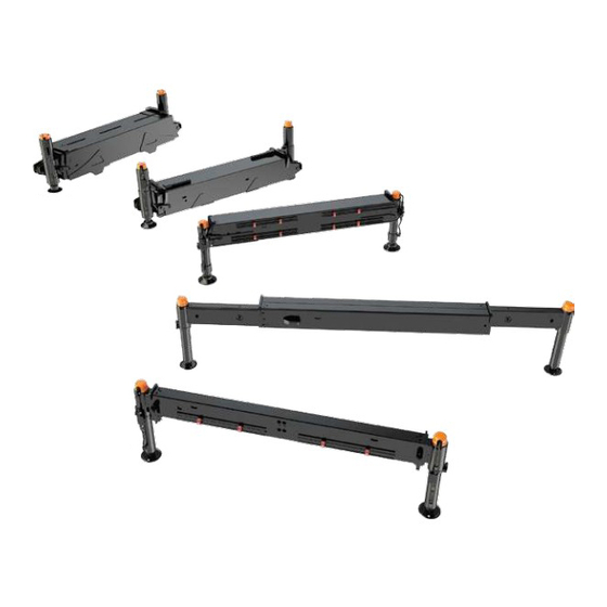
- Installation instructions for supplementary outriggers - 1 - MAIN COMPONENTS AND TERMINOLOGY The stabilizer is made of the following parts and main components: (see Pict. 1) Main beam Extendable rod Cylinder sleeve Stabilizer cylinder Foot plate Rod extension cylinder Lock valve Lock assembly for rods Pict. - Page 8 - Installation instructions for supplementary outriggers - Fixing system by stop ring NORMAL "P" VERSION (Series 4) (see Pict. 4) Stop ring (stop round bar) Cylinder sleeve Slit Cylinder groove Hooking hole Security dowel Pict. 4 Fixing system by spacer (Series 5, 6, 7, 8) (see Pict.
-
Page 9: Choosing The Stabilizer
- Installation instructions for supplementary outriggers - 3 - CHOOSING THE STABILIZER he MAXISTAB range of stabilizers is additional for cranes which already have their own stabilizers, when the stability of the vehicle is not sufficient. In case the vehicle on which a crane is installed is smaller than the minimum vehicle foreseen by the manufacturer for that kind of crane, it will be necessary to install an additional stabilizer. -
Page 10: Calculation Of The Maximum Force Allowed On The Stabilizer
- Installation instructions for supplementary outriggers - 4 - CALCULATION OF THE MAXIMUM FORCE ALLOWED ON THE STABILIZER 1) Column axle offset from the middle of the vehicle to the left or to the right (cm) 2) Longitudinal distance from column centre to the middle of the additional stabilizer, or to the middle of the closest stabilizer... -
Page 11: Table Of Maximum Force Rates Allowed On The Different "Maxistab" Stabilizers
- Installation instructions for supplementary outriggers - TABLE OF MAXIMUM FORCE RATES ALLOWED ON THE DIFFERENT “MAXISTAB” STABILIZERS R allowed R allowed TYPE TYPE (daN) (Lbs) (daN) (Lbs) ML-F 2400 5300 3 EHA 10500 23100 ML-E 1560 3450 4 EHA... -
Page 12: Supplementary Outriggers Installation
- Installation instructions for supplementary outriggers - 5 - SUPPLEMENTARY OUTRIGGERS INSTALLATION The supplementary outriggers can be installed in the following ways: On the chassis by welding the stabilizer to the edge of Counter-frame the counter-frame, or by cutting the same and inserting the stabilizer in an opening made in a middle point of the counter-frame itself. -
Page 13: Choosing The Version
- Installation instructions for supplementary outriggers - the manually operated pins and hookings, the extendable rod handles, the levers of the manual lock valves are always to be easily accessible, and their operation must entail no risk for the user the hydraulic hoses close to the operator must always be properly protected and shielded check that there are no piping or wires pending or protruding under the stabilizer, with following risk of entangling when travelling. - Page 14 - Installation instructions for supplementary outriggers - From series ML/0 up to series 3 Stabilizers series ML-0-1-2-3: you will have to choose among the several versions according to the length of the cylinders, which anyway will have to be moved upwards by following the instructions at § 7. The installer will have to secure again the clamp collars in the position suitable to allow the stabilization, and to prevent cylinders interference with the body side boxes during the extension operation.
-
Page 15: Fixing System By Clamp Collar For Series " Ml " - " 0 " - " 1 " - " 2 " - " 3
- Installation instructions for supplementary outriggers - 7 - FIXING SYSTEM BY CLAMP COLLAR FOR SERIES “ML” – “0” – “1” – “2” – “3” 7.1 Supply conditions The stabilizer is supplied with outrigger cylinders already fixed in the position shown in Pict. -
Page 16: Warnings And Dangers
- Installation instructions for supplementary outriggers - - Tighten slightly the screw (2), paying attention that the collar is completely leaning to the below part of the cylinder sleeve, in case helping by some slight rebound-proof mallet strokes. - Then tighten definitively the screw by the torque wrench to the driving torque shown in the proper table (Tab. -
Page 17: Periodical Checkings
Have screw tightening checked by an authorized workshop and, if necessary, restore it tightening by torque wrench, according to what shown in Tab. 1. Each operation beyond what described has always to be approved by Next Hydraulics’ Technical Department, whom you have to apply to for any clarification and further information required. - Page 18 - Installation instructions for supplementary outriggers - IMPORTANT For a following easy disassembly, it is important to be particularly careful during the greasing and sealing operations, in order to grant an effective protection against water seepages. Disassembly (see Pict. 16-17) STEPS DISASSEMBLY ASSEMBLY...
-
Page 19: -Modification Of A Stabilizer Series "4" Standard Version Into "P" Version
- Installation instructions for supplementary outriggers - 9 -Modification of a stabilizer series “4” standard version into “P” version (with system by stop ring – see Pict. 16) After the cylinder have been disassembled by following the above mentioned instructions, you have to carry out the following operations: Put the cylinder on the lathe, and make a groove in the desired position with same dimensions of the one already existing on the bottom, depth 2.5 mm, R 2.6 mm, by a tool of proper radius... -
Page 20: Special Versions And Optionals
- Installation instructions for supplementary outriggers - 11 - SPECIAL VERSIONS AND OPTIONALS The MAXISTAB stabilizers can be provided with some optionals which can solve problems related to difficult or particular installations. 11.1 “GIR” (tilting) version This version is to be specified on order, and has got slewing cylinders, which can pivot on a pin, with the possibility of pegging the cylinders in transport position to different angles compared to the vertical line. -
Page 21: Dual Side Controls Kit C/W Valve Bank
- Installation instructions for supplementary outriggers - 11.4 Dual side controls kit c/w valve bank This kit is used in case you wish to operate the rear stabilizer directly by a valve bank installed on it. Normally the hoses for connection to the cylinders and the valve bank pass under the stabilizer, and are suitable for installation under the chassis. -
Page 22: Hydraulic Connection Of "Maxistab" Supplementary Outriggers
12.2 Connection piping The connection piping to the hydraulic circuit of MAXISTAB stabilizers can be either a steel stiff type or rubber hoses with steel plaits, but always of a type suitable for high pressure hydraulics. The internal diameters, materials and thicknesses must be suitable to circuit pressures and circulating oil flow. -
Page 23: Double On-Line Relief Valve
- Installation instructions for supplementary outriggers - The maximum working pressure for the Maxistab range hydraulic system is 300 bar. In case of higher pressure, always apply to Next Hydraulics tech. dept for approval. Table 2 12.3.1 Double on-line relief valve This valve (ref. -
Page 24: Hydraulic Scheme For Manual Extendable Stabilizers C/W One Valve Bank Function And "T" Connection Between Crane And Additional Stabilizers
- Installation instructions for supplementary outriggers - 12.4 Hydraulic scheme for manual extendable stabilizers c/w one valve bank function and “T” connection between crane and additional stabilizers Additional stabilizer Main crane stabilizer V Max 150 bar 1) Control valve bank 2) Lock valve 3) Crane stabilizer cylinder 4) Supplementary stabilizer cylinder... -
Page 25: Hydraulic Scheme For Manual Extendable Stabilizers C/W One Valve Bank Function And 5 Ways/4 Pos. Diverter
- Installation instructions for supplementary outriggers - 12.5 Hydraulic scheme for manual extendable stabilizers c/w one valve bank function and 5 ways/4 pos. diverter Alternative: manually operated lock valve Additional stabilizer Main crane stabilizer V max 150 bar 1) Control valve bank 2) Lock valve 3) Crane stabilizer cylinder 4) Diverter... -
Page 26: Hydraulic Scheme For Hydraulic Extendable Stabilizers C/W One Valve Bank Function And Two 5 Ways/4 Pos. Diverters
- Installation instructions for supplementary outriggers - 12.6 Hydraulic scheme for hydraulic extendable stabilizers c/w one valve bank function and two 5 ways/4 pos. diverters Alternative: manually operated lock valve Additional stabilizer Main crane stabilizer V max 150 bar 1) Control valve bank 6) Additional stabilizer diverter 2) Crane stabilizer diverter 7) Additional stabilizer cylinder... -
Page 27: Hydraulic Scheme For Hydraulic Extendable Stabilizers C/W Two Independent 4 Functions Valve Banks (One For The Crane And One For The Additional Stabilizers)
- Installation instructions for supplementary outriggers - 12.7 Hydraulic scheme for hydraulic extendable stabilizers c/w two independent 4 functions valve banks (one for the crane and one for the additional stabilizers) Alternative: manually operated lock valve Additional stabilizer Main crane stabilizer V max p max p max... -
Page 28: Hydraulic Scheme For Manual Extendable Stabilizers C/W Two Independent 2 Functions Valve Banks
- Installation instructions for supplementary outriggers - 12.8 Hydraulic scheme for manual extendable stabilizers c/w two independent 2 functions valve banks Alternative: manually operated lock valve Additional stabilizer Main crane stabilizer V max 150bar 150bar 1) Crane stabilizer cylinder 2) Lock valve 3) Crane stabilizer valve bank 4) Additional stabilizer valve bank Pict. -
Page 29: Hydraulic Connection Of The Rod Extension Cylinders For Models "1 Eho" - "2 Eho
- Installation instructions for supplementary outriggers - 13 - HYDRAULIC CONNECTION OF THE ROD EXTENSION CYLINDERS FOR MODELS “1 EHO” – “2 EHO” In picture 27 are shown the connection inlets for the rod extension cylinders, in order to make the correct mounting easier. -
Page 30: Instructions For Fixing And Connecting The Kit Microswitches For Not Locked Extendable Rods
- Installation instructions for supplementary outriggers - 14 - INSTRUCTIONS FOR FIXING AND CONNECTING THE KIT MICROSWITCHES FOR NOT LOCKED EXTENDABLE RODS The kit warns the driver, when manually operated extension rods are not locked in the transport position. That kit is to be ordered separately, and is supplied with instructions sheet. -
Page 31: Decals Application
Pict. 30 Each MAXISTAB stabilizer is equipped with a sealed envelope holding the decals and the safety warnings required. Such decal kit must be applied to the stabilizer, after its final painting, as shown in pict. 30. When delivering the stabilizer to the end customer, always make sure that it is fitted with all the warnings and decals shown in the picture. -
Page 32: Storage And Handling Instructions
- Installation instructions for supplementary outriggers - 16 - STORAGE AND HANDLING INSTRUCTIONS The MAXISTAB stabilizers can be delivered to the installer on different sorts of packing, generally pallets or wooden frame suitable for handling by forklifts or transpallets. Each stabilizer is supplied along with: CE Conformity Declaration decal kit as described in Section 15. -
Page 33: Table Of Weights W/O Packing
- Installation instructions for supplementary outriggers - TABLE OF WEIGHTS W/O PACKING Model Model Model Model ML - F ML - E 1 EMA 5 EXHA 0 EMO 1 EHA 5 EXPHA 1010 1 EMO 2 EMA 6 EXHA 1210 1 EHO 6 EXPHA 1360... -
Page 34: Finishing And Painting Of "Maxistab" Stabilizers
- Installation instructions for supplementary outriggers - 17 - FINISHING AND PAINTING OF “MAXISTAB” STABILIZERS The stabilizers are supplied painted with EPOXY priming coat of half-luster black colour. This product is an excellent support, after the mounting and installing operations, for the application of a final paint, as mentioned in the warning decal applied to each stabilizer. -
Page 35: Stabilizers' User Manual
Use and maintenance manual 18 - STABILIZERS’ USER MANUAL The following pages include the instructions for use for MAXISTAB supplementary outriggers. The installer must take care of enclosing such pages (in case even photocopying them) in the user manual he has to provide to the end user, as foreseen in the Machine Directive. -
Page 36: Operating Instructions
- Installation instructions for supplementary outriggers - Use and maintenance manual 18.2 - Operating instructions 18.2.1 General attentions The equipment is to be used exclusively by qualified and skilled staff. They must know locations and functioning of every control, instruments, indicator, warning light, plate and sticker DANGER! Before starting any operation, make sure that nobody is present in the working area of the... -
Page 37: Hydraulic Stabilizer
- Installation instructions for supplementary outriggers - Use and maintenance manual Lower the foot plates one at a time by operating as follows: 18.2.2 Hydraulic stabilizer Manual lock valve (Pict. 34) Open the manual lock valve (1), in order to allow the lowering to the ground of the foot plate (2). -
Page 38: Automatically Tilting Hydraulic Stabilizer
- Installation instructions for supplementary outriggers - Use and maintenance manual 18.2.4 Automatically tilting hydraulic stabilizer The automatically tilting device system is applicable on request to the stabilizers of series “4”, “5”, “6”. With such system, the stabilizer leg rotation is induced by the rod stroke. -
Page 39: Regular Checks
Tab. 1. Each operation beyond what described has always to be approved by Next Hydraulics’ Technical Department, whom you have to Pict. 39 apply to for any clarification and further information required. - Page 41 Via MEDITERRANEO, 6 - 42022 BORETTO (REGGIO Emilia) - Italy Tel. 0522 / 96 30 08 - Fax 0522 / 96 30 39 - info@maxiliftcrane.com MD.0.157 GB...
Need help?
Do you have a question about the MAXISTAB and is the answer not in the manual?
Questions and answers