Table of Contents
Advertisement
Quick Links
"THIS MANUAL INCLUDES TELEPHONICS PROPRIETY DATA AND SHALL NOT BE
DUPLICATED, USED, OR DISCLOSED, IN WHOLE OR IN PART."
TM115007 Rev A (04/07)
USER'S MANUAL
FOR THE
TRULINK
WIRELESS INTERCOM
SYSTEM
April 2007
Prepared by:
TELEPHONICS CORPORATION
815 Broad Hollow Road
Farmingdale, New York 11735
®
USA
Advertisement
Table of Contents

Summary of Contents for Telephonics Trulink
- Page 1 WIRELESS INTERCOM SYSTEM April 2007 Prepared by: TELEPHONICS CORPORATION 815 Broad Hollow Road Farmingdale, New York 11735 “THIS MANUAL INCLUDES TELEPHONICS PROPRIETY DATA AND SHALL NOT BE DUPLICATED, USED, OR DISCLOSED, IN WHOLE OR IN PART.” TM115007 Rev A (04/07)
- Page 2 Revision # USER’S MANUAL FOR THE ® TRULINK WIRELESS INTERCOM SYSTEM Copyright © 2007 Telephonics Corporation Publication No.: TM115007 All Rights Reserved Printed in U.S.A. Telephonics Corporation 815 Broad Hollow Road, Farmingdale, New York 11735 Telephone: (877) 517-2327 Fax: (877) 755-7701...
- Page 3 E L E P H O N I C S O R P O R A T I O N Document No.: PC7155H0 Revision # FCC COMPLIANCE This device complies with part 15 of the FCC Rules. Operation is subject to the following two conditions: (1) This device may not cause harmful interference, and (2) this device must accept any interference received, including interference that may cause undesired operation.
- Page 4 E L E P H O N I C S O R P O R A T I O N O M M U N I C A T I O N Y S T E M S I V I S I O N DOCUMENT COMPATIBILITY PRODUCT/PROJECT REVISIONS/VERSIONS...
- Page 5 E L E P H O N I C S O R P O R A T I O N O M M U N I C A T I O N Y S T E M S I V I S I O N REVISION HISTORY SHEET REVISION APPROVAL DATE...
-
Page 6: Table Of Contents
PAGE CHAPTER 1 GENERAL DESCRIPTION INTRODUCTION.....................1-1 DEFINITIONS AND ABBREVIATIONS ...............1-1 1.2.1 Definitions of Terms Used ..................1-1 1.2.2 Abbreviations and Acronyms..................1-1 TRULINK DESCRIPTION ..................1-2 NETWORK CONFIGURATION ................1-2 CAPABILITIES ......................1-2 TRULINK EQUIPMENT ..................1-3 CHAPTER 2 OPERATION OVERVIEW......................2-1 PHYSICAL DESCRIPTION ..................2-1 BATTERIES ......................2-1 2.3.1... - Page 7 Logging on to a Network ..................3-6 3.4.6 Status Indications ......................3-6 3.4.6.1 Power-On BIT Failure....................3-6 TAP CHECK OUT PROCEDURE ................3-7 CHAPTER 4 TRULINK DUAL PORT TRANSCEIVER OVERVIEW......................4-1 PHYSICAL DESCRIPTION ..................4-2 OPERATION ......................4-2 4.3.1 ICS Interface ......................4-3 4.3.2 Logging on to a Network ..................4-3 DUAL PORT TRANSCEIVER CHECK OUT PROCEDURE........4-4...
- Page 8 I V I S I O N LIST OF ILLUSTRATIONS TITLE PAGE Figure 1.6-1. TruLink Components..................1-4 Figure 2.3.2-1. TruLink Portable Transceiver (TPT) ..............2-2 Figure 2.3.4-1. TPT Unit Dimensions (Inches) ................2-4 Figure 2.3.4-2. Battery Installation....................2-5 Figure 3.1-1. TPT and TAP Network ..................3-1 Figure 3.3.1-1.
-
Page 9: Introduction
GENERAL INTRODUCTION ® This document will introduce the operator to the many features and capabilities of TruLink Wireless Intercommunication System. It will provide the operator with the instructions necessary for the proper handling and operation of TruLink and its component parts, and basic instructions for maintaining the TruLink in proper working order. -
Page 10: Trulink Description
A picture of each of the units in the TruLink system is shown in Figure 1.6-1. NETWORK CONFIGURATION A TruLink network is composed of one master unit and a group of slave units. The master unit is the central point of the TruLink network. All slave-to-slave communications are routed through the master. -
Page 11: Trulink Equipment
O M M U N I C A T I O N Y S T E M S I V I S I O N TRULINK EQUIPMENT The TruLink system can be composed of the following equipment: Table 1.6.1 TruLink Equipment List NAME... -
Page 12: Figure 1.6-1. Trulink Components
O M M U N I C A T I O N Y S T E M S I V I S I O N Figure 1.6-1. TruLink Components TM115007 REV A (04/07) USE OR DISCLOSURE OF DATA CONTAINED ON THIS PAGE IS SUBJECT TO THE... -
Page 13: Chapter 2 Operation
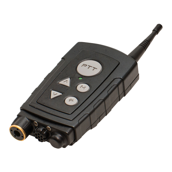
OPERATION OVERVIEW The TPT is the portable unit in the TruLink wireless communication system. The operator wears the TPT along with a headset that includes headphones and a microphone. The TPT has an operator interface consisting of buttons for input and an audio voice menu, known as SynVoice, for output. -
Page 14: Battery Type
Note Batteries are not included in the purchase of the TPT or DTP. Figure 2.3.2-1. TruLink Portable Transceiver (TPT) TM115007 REV A (04/07) USE OR DISCLOSURE OF DATA CONTAINED ON THIS PAGE IS SUBJECT TO THE RESTRICTION ON THE TITLE PAGE OF THIS DOCUMENT... -
Page 15: Low Battery Warning
E L E P H O N I C S O R P O R A T I O N O M M U N I C A T I O N Y S T E M S I V I S I O N TPT BUTTON FUNCTION ∧... -
Page 16: Figure 2.3.4-1. Tpt Unit Dimensions (Inches)
E L E P H O N I C S O R P O R A T I O N O M M U N I C A T I O N Y S T E M S I V I S I O N Figure 2.3.4-1. -
Page 17: Figure 2.3.4-2. Battery Installation
E L E P H O N I C S O R P O R A T I O N O M M U N I C A T I O N Y S T E M S I V I S I O N Figure 2.3.4-2. -
Page 18: Antenna
E L E P H O N I C S O R P O R A T I O N O M M U N I C A T I O N Y S T E M S I V I S I O N ANTENNA The TPT antenna is designed with a flexible tip for rugged use. -
Page 19: Table 2.6.1-1 Led Indications
E L E P H O N I C S O R P O R A T I O N O M M U N I C A T I O N Y S T E M S I V I S I O N Table 2.6.1-1 LED Indications STATUS... - Page 20 E L E P H O N I C S O R P O R A T I O N O M M U N I C A T I O N Y S T E M S I V I S I O N Table 2.6.1-1 LED Indications (Continued) Green...
-
Page 21: Audible Indicators
E L E P H O N I C S O R P O R A T I O N O M M U N I C A T I O N Y S T E M S I V I S I O N 2.6.2 Audible Indicators The TPT sends a number of different tones to the operator headset. -
Page 22: Table 2.3.6-1 Summary Of Available Synvoice Phrases (Configuration-Dependant)
E L E P H O N I C S O R P O R A T I O N O M M U N I C A T I O N Y S T E M S I V I S I O N Table 2.3.6-1 Summary of Available SynVoice Phrases (Configuration-Dependant) PHRASE... -
Page 23: Tpt Operation
I V I S I O N TPT OPERATION The TruLink network is designed to operate with one unit functioning as a MASTER and all other units as SLAVES. The MASTER broadcasts received audio from one slave TPT to all other SLAVE TPTs on the wireless network, as well as the wired ICS. -
Page 24: Starting A Network
O M M U N I C A T I O N Y S T E M S I V I S I O N These are the only options available until the TPT is part of a TruLink network. 2.7.3.1 Starting a Network When not located near the MASTER TAP or DPT, a group of TPTs can set up a standalone network. -
Page 25: Settings
E L E P H O N I C S O R P O R A T I O N O M M U N I C A T I O N Y S T E M S I V I S I O N If logon fails due to a mismatch of system configuration, the operator will hear a SynVoice message “CONFIGURATION ERROR”... -
Page 26: Vox Setting
E L E P H O N I C S O R P O R A T I O N O M M U N I C A T I O N Y S T E M S I V I S I O N To confirm the selected channel, press PTT. -
Page 27: Order Change Master Setting
E L E P H O N I C S O R P O R A T I O N O M M U N I C A T I O N Y S T E M S I V I S I O N Off –... -
Page 28: Talking On The Network
E L E P H O N I C S O R P O R A T I O N O M M U N I C A T I O N Y S T E M S I V I S I O N 2.8.2 Talking on the Network The user is offered three methods of speaking on the network. -
Page 29: Key-Click
E L E P H O N I C S O R P O R A T I O N O M M U N I C A T I O N Y S T E M S I V I S I O N The SLAVE automatically tries to re-logon to the same MASTER. -
Page 30: Chapter 3 Trulink Access Point
TRULINK ACCESS POINT OVERVIEW The TruLink Access Point (TAP) is used as either the long-range radio interface or as an interface to a wired ICS. It is typically used for fixed installations. One TPT SLAVE and one TAP MASTER, as shown in Figure 3.1-1, constitute a network. -
Page 31: Physical Description
E L E P H O N I C S O R P O R A T I O N O M M U N I C A T I O N Y S T E M S I V I S I O N PHYSICAL DESCRIPTION The TAP is powered by DC power from the host vehicle. -
Page 32: Connections
E L E P H O N I C S O R P O R A T I O N O M M U N I C A T I O N Y S T E M S I V I S I O N LED Button Data (Not seen) -
Page 33: Data Connectors
When the TAP is configured for use with a wired intercom system, this procedure must be employed to eliminate echo in the TruLink system caused by the wired ICS station’s sidetone. The following procedure usually is required only during a wired system installation or replacement of a wired system intercom station. -
Page 34: Order Synchronize Access Point Setting (Change Tap Channels)
E L E P H O N I C S O R P O R A T I O N O M M U N I C A T I O N Y S T E M S I V I S I O N Ensure all other stations are not transmitting on the intercom or have an open MIC. -
Page 35: Logging On To A Network
E L E P H O N I C S O R P O R A T I O N O M M U N I C A T I O N Y S T E M S I V I S I O N ORDER CHANGE MASTER is used to switch out the MASTER unit of a network. -
Page 36: Tap Check Out Procedure
E L E P H O N I C S O R P O R A T I O N O M M U N I C A T I O N Y S T E M S I V I S I O N TAP CHECK OUT PROCEDURE The following should be performed before using a TAP. -
Page 37: Chapter 4 Trulink Dual Port Transceiver
Y S T E M S I V I S I O N CHAPTER 4 TRULINK DUAL PORT TRANSCEIVER OVERVIEW The Dual Port Transceiver (DPT) is typically employed for temporary connections to wired intercom systems. When connected to the wired system, it acts like a TAP and is usually the network master. -
Page 38: Physical Description
Please refer to that section for details. Note Rechargeable batteries (NiMH) must be removed from the DPT and charged in a commercial battery charger. The TruLink Support Station, 780-3000-001, cannot be employed to charge the DPT’s batteries. TM115007 REV A (04/07) -
Page 39: Ics Interface
When the DPT is configured for use with a wired intercom system, this procedure must be employed to eliminate echo in the TruLink system caused by the station’s sidetone. This procedure will eliminate echo on a TPT when a DPT is connected to a wired system. -
Page 40: Dual Port Transceiver Check Out Procedure
E L E P H O N I C S O R P O R A T I O N O M M U N I C A T I O N Y S T E M S I V I S I O N If echo is heard, reduce the station’s volume control slightly until the echo is eliminated. -
Page 41: Chapter 5 Trulink Support Station
PHYSICAL CHARACTERISTICS The TSS is powered by standard 120VAC, 60Hz power. The AC power cable, Telephonics Part No. 780-3500-001, is supplied with the TSS. The TSS measures 11.75 inches in length by 9.75 inches wide by 4.75 inches high and weighs approximately 12 pounds. -
Page 42: Charge Indication
E L E P H O N I C S O R P O R A T I O N O M M U N I C A T I O N Y S T E M S I V I S I O N DO NOT CHARGE ALKALINE DO NOT CHARGE ALKALINE BATTERIES. -
Page 43: Bit Indication
E L E P H O N I C S O R P O R A T I O N O M M U N I C A T I O N Y S T E M S I V I S I O N Table 5.3-1 Charge LED Indication CURRENT STATUS... -
Page 44: Tss Check Out Procedure
E L E P H O N I C S O R P O R A T I O N O M M U N I C A T I O N Y S T E M S I V I S I O N TSS CHECK OUT PROCEDURE The following should be performed before using the TSS: Connect the unit to 120 VAC. - Page 45 E L E P H O N I C S O R P O R A T I O N O M M U N I C A T I O N Y S T E M S I V I S I O N APPENDIX A UNIT SPECIFICATIONS TM115007 REV A (04/07)
- Page 46 E L E P H O N I C S O R P O R A T I O N O M M U N I C A T I O N Y S T E M S I V I S I O N TPT AND DPT SPECIFICATIONS DESCRIPTION VALUE...
- Page 47 E L E P H O N I C S O R P O R A T I O N O M M U N I C A T I O N Y S T E M S I V I S I O N TAP SPECIFICATIONS DESCRIPTION VALUE...
- Page 48 E L E P H O N I C S O R P O R A T I O N O M M U N I C A T I O N Y S T E M S I V I S I O N TSS SPECIFICATIONS DESCRIPTION VALUE...
- Page 49 E L E P H O N I C S O R P O R A T I O N O M M U N I C A T I O N Y S T E M S I V I S I O N APPENDIX B CONNECTOR DATA TM115007 REV A (04/07)
- Page 50 O R P O R A T I O N O M M U N I C A T I O N Y S T E M S I V I S I O N TruLink Access Point (TAP) LRU ID: J1 Audio Interface Protective Cap PN: 8LTE02B13...
- Page 51 O M M U N I C A T I O N Y S T E M S I V I S I O N LRU ID: TruLink Access Point (TAP) LRU CONNECTOR: J2 Data Interface Protective Cap P/N: 8LTE02B09 CONNECTOR STD: MIL-C 38999 MATING CONN.
- Page 52 O M M U N I C A T I O N Y S T E M S I V I S I O N LRU ID: TruLink Access Point (TAP) LRU CONNECTOR: J3 Audio Interface CONNECTOR STD: MIL- MIL-C 38999 MATING CONN.
- Page 53 O M M U N I C A T I O N Y S T E M S I V I S I O N LRU ID: TruLink Access Point (TAP) J4 Data Interface Protective Cap P/N: 8LTE02B09 LRU CONNECTOR: CONNECTOR STD: MIL-C 38999 MATING CONN.
- Page 54 O M M U N I C A T I O N Y S T E M S I V I S I O N LRU ID: TruLink™ Access Point (TAP) LRU CONNECTOR: J5 Audio Interface Protective Cap PN: 8LTE02B13 CONNECTOR STD: MIL--C 38999 MATING CONN.
- Page 55 O R P O R A T I O N O M M U N I C A T I O N Y S T E M S I V I S I O N POWER TruLink Access Point (TAP) LRU ID: Power LRU CONNECTOR: CONNECTOR STD: MIL-C 26482 MATING CONN.
- Page 56 E L E P H O N I C S O R P O R A T I O N O M M U N I C A T I O N Y S T E M S I V I S I O N TPT CONNECTORS The TPT connector is a female 4-pole NEXUS receptacle.
- Page 57 E L E P H O N I C S O R P O R A T I O N O M M U N I C A T I O N Y S T E M S I V I S I O N TSS CONNECTORS Power Input Connector: AMPENOL T3110000...
- Page 58 E L E P H O N I C S O R P O R A T I O N O M M U N I C A T I O N Y S T E M S I V I S I O N Table 1 Pin-out of 7-Pole Headset Jack PIN NR J2...
- Page 59 E L E P H O N I C S O R P O R A T I O N O M M U N I C A T I O N Y S T E M S I V I S I O N Table 2 Pin-out of 8-Pole Audio Jack PIN NR J3...
Need help?
Do you have a question about the Trulink and is the answer not in the manual?
Questions and answers