Table of Contents
Advertisement
Quick Links
Advertisement
Table of Contents

Summary of Contents for Norwood Kwik-Till HSD2575
- Page 1 2015 OWNER’S MANUAL OWNER’S MANUAL...
- Page 2 Read this manual before operating your Norwood equipment. The information presented will prepare you to do a better and safer job. Keep this manual handy for ready reference. Require all operators to read this manual carefully and become acquainted with all the adjustment and operating procedures before attempting to operate.
- Page 3 Quick Reference Guide Connect Hydraulics Insert the males ends into the couplers on the tractor, Be sure to match pressure and return lines to one valve bank and make sure they are locked in place. See Below for Color Code Chart Transporting Use clevis style hitch on the tractor.
- Page 4 Field Operation After placing machine in field position retract wheel cylinders (#1) and packer cylinders (#2) to the cylinder stops. Depth Stop Size Digging Depth 3/4” 5/8” II. It may be necessary to adjust digging depth, this is done by extending wheel cylinders (#1) 1”...
-
Page 5: Table Of Contents
Table of Contents Introduction ....................Inside Front Cover General Information ......................5 Dimensions & Specifications ....................6 Safety & Instructional Decals ....................7 Safety ..........................11 Operation .......................... 15 Maintenance ........................23 Trouble Shooting ........................ 28 Index to Parts List ......................29 Bolt Torque Chart ....................... -
Page 6: Dimensions & Specifications
Dimensions & Specifications 25’ 30’ 34’ 40’ Unfolded Length (A) 27’ 3” 31’ 2” 34’ 8” Unfolded Width (B) 25’ 10” 30’ 10” 34’ 1” 40’ 10” Working Width (C) 25’ 0” 30’ 0” 33’ 4” 40’ 0” Packer Width (D) 7’... - Page 7 Dimensions & Specifications 55-5-00002 01/01/2015 (Rev A)
-
Page 8: Safety & Instructional Decals
Safety & Instructional Decals 90-44-0181 Sign, SMV 55-5-00002 01/01/2015 (Rev A) - Page 9 Safety & Instructional Decals 90-44-0190 Decal, Danger Pinch & Crushing Hazard 90-44-0191 Decal, Warning Maximum Speed 90-44-0192 Decal, Caution Hyd Control Hazard 90-44-0187 Decal, Danger Negative Hitch Weight 90-44-0193 Decal, Warning Electrocution Hazard 90-44-0188 Decal, Danger Crushing Hazard 90-44-0194 Decal, Warning High Pressure Hyd Oil 90-44-0189 Decal, Warning Runaway Hazard 55-5-00002...
- Page 10 90-44-0216 Decal, HSD3425 (4”) Decal, HSD3425 (3”) 90-44-0205 90-44-0217 Decal, HSD4075 (4”) Decal, HSD4075 (3”) 90-44-0209 Decal, Norwood Logo (6”) 90-44-0196 Decal, Information Hose Color Chart Large Kwik-Till Logo Small Kwik-Till Logo 90-44-0199 90-44-0211 Decal, HSD2000 (6”) Decal, HSD2000 (4”)
-
Page 11: Safety
Safety Safety is a primary concern in the design and • Keep hands, feet and clothing away from all manufacturing of our products. Unfortunately, our moving parts. efforts to provide safe equipment can be wiped out by a single careless act of an operator. •... - Page 12 Check Lists Pre-Delivery Check List Delivery Check List (Dealer’s Responsibilitys) (Dealer’s Responsibilitys) Inspect the equipment thoroughly after assembly to ✓ Show customer how to make adjustments. ensure it is set up properly before delivering it to the customer. ✓ Instruct customer how to lubricate and explain importance of lubrication.
- Page 13 Operator Sign-Off Record Safety is a primary concern in the design and American Society of Agricultural & biological Engineers (ASAE) and the Occupational Safety and manufacture of our products. Unfortunately, our efforts Health Administration (OSHA). to provide safe equipment can be wiped out by a single Anyone will operating...
- Page 14 55-5-00002 01/01/2015 (Rev A)
-
Page 15: Operation
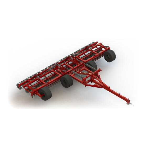
• Always comply with all state and local lighting (Replacement manuals are available from your and marking requirements. Norwood dealer.) Failure to follow instructions or safety rules can result in serious injury or • Always wear relatively tight and belted death. - Page 16 Operation Principle Components The disc-angles are for high speed and The Norwood Kwik-Till consists of rear folding medium to shallow penetration, they chop and mix frames, individual disc assemblies, and rolling baskets. trash and soil for a superior mixing action. The roller...
- Page 17 Operation Pre-Operation Check List (OWNER’S RESPONSIBILITY) ✓ Check all lubrication points and grease as required. ✓ Check that the unit is properly attached to the This Pre-Operation Check List is provided for tractor. On pull-type unit, be sure there is a the operator.
- Page 18 Operation Attaching to Tractor Connecting the Hydraulics • Do not allow anyone to stand between Use a clean cloth or paper towel to clean the couplers on the end of the hoses and the area tractor and unit when backing up to the around the couplers on the tractor.
- Page 19 Operation Unfolding Machine into Field Position Move machine onto level ground so it is straight With wings fully opened and wing cylinders in behined the tractor. float, extend transport cylinders (#4) to lower machine fully to the ground. When machine is completely to the ground place transport cylinders Remove wing transport pins from wings and place (#4) into float position.
- Page 20 Operation Figure 10. Depth Settings 2.50” Field Operation After placing machine in field position retract wheel cylinders (#1) and basket cylinders (#2) to the cylinder stops. It may be necessary to adjust digging depth, this is done by raising wheel cylinders (#1) and basket cylinders (#2) and adding cylinder stops for shallower, or removing stops for deeper depth.
- Page 21 Operation Folding Machine into Transport Position Move machine onto level ground so it is straight Retract the wing cylinders (#3) to fold wings, behind the tractor. When wing nears wing rest adjust transport cylinder (#4) so wing roller is just above wing Extend the wheel cylinders (#1) and the basket rest, then completely retract wing cylinders cylinders (#2) to lift machine off the ground.
- Page 22 Operation Tansporting the Unit Storage • Never allow riders on power unit or • Block equipment securely for storage. attachment. • Keep children and bystanders away from storage area. At the end of the season, the Kwik-Till should be thoroughly inspected and prepared for storage. •...
-
Page 23: Maintenance
Service & Maintenance • Before dismounting power unit or performing any • Always wear relatively tight and belted clothing service or maintenance, follow these steps: to avoid entanglement in moving parts. Wear sturdy, rough-soled work shoes and protective Disengage power to equipment. ✓... - Page 24 Service & Maintenance Lubrication Schedule NOTE: Recommendations are based on normal operating conditions. Severe or unusual conditions may require more frequent lubrication or oil changes. Refer to Figure 16. Daily or every 12 hours 25 hours 40 hours Annually Figure 16. Lubrication Points 55-5-00002 01/01/2015 (Rev A)
- Page 25 Service & Maintenance Daily or every 12 hours of operation Check for Hydraulic Leaks Check for Damage Hoses, Fittings, and Valves Check Tire Pressures 46 Psi (317 kPa) Check Scraper alignment if equiped with Rubber Roller Basket Figure 17. Roller Packer Bearing Grease Point Every 25 hours of operation Figure 18.
- Page 26 Service & Maintenance Annually Figure 22. Wing Transport Roller Grease Point Figure 23. Wheel Hub Grease Point Check for Loose Hardware Check for Damage and/or Excessive Wear to discs Check Wheel Bearings Check Disc Hubs Check Rubber Cord Alignment 55-5-00002 01/01/2015 (Rev A)
- Page 27 Service & Maintenance Lubrication Service Record Note: See prior pages for details. Copy this page to contiue service records. L = Lubricate C = Check 12 Hours or Daily 25 Hours Anually Date: Serviced By: 55-5-00002 01/01/2015 (Rev A)
-
Page 28: Trouble Shooting
Trouble Shooting Problem Cause Solution Machine doesn’t Add or Remove cylinder stops as needed to Machine not level from front to back track straight level machine Ground speed too slow Increase speed as specified in operations Entire machine plugs Working depth too deep Add cylinder stops as needed Verify same number of cylinders stop on main frame and wings... -
Page 29: Index To Parts List
Parts Index The illustrations and data used in this manual were current at the time of printing, but due to possible in-line production changes, your machine may vary slightly in detail. We reserve the right to redesign and change the machines as may be necessary without notification. Hitch Components (26’-30’) .............. - Page 30 Hitch Components (26’ - 30’) 55-5-00002 01/01/2015 (Rev A)
- Page 31 Hitch Components (26’ - 30’) Item No. Part No. Description Qty. 55-3-00084* Hitch Weld - 26’ & 30’ 55-4-00176 Light Bracket 55-4-00423 Wing Lock Pin 90-42-2009 Hydraulic Jack 90-39-0020 Hyd Cylinder, 5 x 36 90-36-0038 Crossover Relief 90-36-0036 Accumulator, 1.5L 90-36-0035 Accumulator Clamp 90-18-0002...
- Page 32 Hitch Components (34’ - 40’) 55-5-00002 01/01/2015 (Rev A)
- Page 33 Hitch Components (34’ - 40’) Item No. Part No. Description Qty. 55-3-00011* Hitch Weld - 40’ 55-3-00036* Hitch Weld - 34’ 90-42-2009 Hydraulic Jack 90-34-0009 Hose Holder Spring 90-99-0008 Manual Tube 90-42-0012 Hitch Tongue Camp Cat4 55-4-00239 Safety Chain Tab 90-42-0010 Safety Chain (21,000 Lb) 90-18-0002...
- Page 34 Main Frame Components (34’ - 40’) 55-5-00002 01/01/2015 (Rev A)
- Page 35 Main Frame Components (34’ - 40’) Item No. Part No. Description Qty. 55-3-00012* Main Frame Weld - 40’ 55-3-00037* Main Frame Weld - 34’ 55-4-00176 Light Bracket 55-4-00423 Wing Lock Pin 55-4-00465 Accumulator Mount 55-4-00549 Pressure Relief Mount 90-39-0010 Hyd Cylinder, 5 x 48 90-39-2004 Hyd Cylinder Pin, 1-1/4”...
- Page 36 Wing Components 55-5-00002 01/01/2015 (Rev A)
- Page 37 Wing Components Item No. Part No. Description Qty. 55-3-00001* Wing Frame Weld - LH (40’) 55-3-00006* Wing Frame Weld - RH (40’) 55-3-00041* Wing Frame Weld - LH (34’) 55-3-00040* Wing Frame Weld - RH (34’) 55-3-00063* Wing Frame Weld - LH (30’) 55-3-00133* Wing Frame Weld - RH (30’) 55-3-00053*...
- Page 38 Wing Components 55-5-00002 01/01/2015 (Rev A)
- Page 39 Wing Components Item No. Part No. Description Qty. 90-20-0503 U-Bolt, 3/8-16 x 6 x 7-1/4, Gr5 90-10-2849 Hex Bolt, 3/4-10 x 4, Gr5 90-10-2389 Hex Bolt, 5/8-11 x 6, Gr5 90-10-0793 Hex Bolt, 3/8-16 x 1-1/2, Gr5 90-10-5601 Hex Bolt, M12-1.25 x 22, CL8.8 90-10-7151 Carriage Bolt, 3/8-16 x 2-1/2, Gr5 90-10-7248...
- Page 40 Center Components Item No. Part No. Description Qty. 55-3-00003* Center Frame Weld - 40’ 55-3-00039* Center Frame Weld - 34’ 55-3-00131* Center Frame Weld - 30’ 55-3-00085* Center Frame Weld - 26’ 55-5-00002 01/01/2015 (Rev A)
- Page 41 Center Components Item No. Part No. Description Qty. 55-3-00008* Center Strut Weld - 40’ 55-3-00038* Center Strut Weld - 34’ 55-3-00055* Center Strut Weld - 30’ / 26’ 55-3-00016* Disc Arm Weld - 14° 55-3-00015* Disc Arm Weld - 17° 55-4-00091* Disc Arm Cap 55-3-00017...
- Page 42 Packer Components Item No. Part No. Description Qty. 55-3-00019* Center Packer Mount Frame - 40’ 55-3-00044* Center Packer Mount Frame - 34’ 55-3-00066* Center Packer Mount Frame - 30’ 55-3-00060* Center Packer Mount Frame - 26’ 55-5-00002 01/01/2015 (Rev A)
- Page 43 Packer Components Item No. Part No. Description Qty. 55-3-00018* Wing Packer Mount Frame - 40’ 55-3-00042* Wing Packer Mount Frame - 34’ 55-3-00064* Wing Packer Mount Frame - 30’ 55-3-00059* Wing Packer Mount Frame - 26’ 55-3-00124 Scraper Mount Tube Frame - 40’ 55-3-00177 Scraper Mount Tube Frame - 34’...
- Page 44 Hydraulic Components (26’ - 30’) Item No. Part No. Description Machine Size Qty. 90-37-1155 Hose, 08 x 22”, 08 FJX x 08 FJX90 90-37-1163 Hose, 06 x 38”, 06 FJX x 06 FJX 30’ 90-37-1146 Hose, 06 x 32”, 06 FJX x 06 FJX 26’...
- Page 45 Hydraulic Components (26’ - 30’) Item No. Part No. Description Machine Size Qty. 90-37-1170 Hose, 06 x 69”, 06 FJX x 08MP 90-37-1166 Hose, 06 x 48”, 06 FJX x 06 FJX 30’ 90-37-1126 Hose, 06 x 50”, 06 FJX x 06 FJX 26’...
- Page 46 Hydraulic Components (34’ - 40’) 55-5-00002 01/01/2015 (Rev A)
- Page 47 Hydraulic Components (34’ - 40’) Item No. Part No. Description Machine Size Qty. 90-37-1155 Hose, 08 x 22”, 08 FJX x 08 FJX90 90-37-1126 Hose, 06 x 50”, 06 FJX x 06 FJX 40’ 90-37-1125 Hose, 06 x 37”, 06 FJX x 06 FJX 34’...
- Page 48 Hydraulic Components (34’ - 40’) 55-5-00002 01/01/2015 (Rev A)
- Page 49 Hydraulic Components (34’ - 40’) Item No. Part No. Description Machine Size Qty. 90-39-0010 Cylinder, 5” Bore x 48” Stroke 40’ / 34’ 90-36-0036 Accumulator - 1.5L ACSL 90-36-0038 Crossover Relief (30 GPM) 90-36-0021 Manifold 90-38-0118 Quick Coupler, Male, 8FP 90-38-0114 Adapter, 90°...
-
Page 50: Bolt Torque Chart
Bolt Torque Chart Standard Torque Chart Always tighten hardware to these values unless a different torque value or tightening procedure is listed for a specific application. Fasteners must always be replaced with the same grade as specified in the manual parts list. Make sure fastener threads are clean and you properly start thread engagement. -
Page 51: Abbreviations
Abbreviations AG ............Agriculture MO ........... Male O-Ring Boss ASAE ..American Society of Agricultural Engineers MJ ............Male JIC ATF ......Automatic Transmission Fluid MJX ..........Male Swivel JIC BSPP ......British Standard Pipe Parallel MP ............Male Pipe BSPTM .... -
Page 52: Index
Index Index General Maintenance Abbreviations ..........31 Safety ............23 Bolt Torque Chart ..........30 Lubricants ............23 Dimensions & Specifications ......6-7 Greasing ............23 General Information ........... 5 Lubrication Schedule ........24-26 Introduction ............2 Lubrication Service Record ........ 27 Warranty Registration &... - Page 53 55-5-00002 01/01/2015 (Rev A)
-
Page 54: Warranty Registration & Inspection Report
Warranty Warranty Registration ________________________________________ ________________________________________ Customer’s Name Dealer’s Name ________________________________________ ________________________________________ ________________________________________ ________________________________________ Address Address _______________________ ____ _________ _______________________ ____ _________ City State Area Code City State Area Code ________________________________________ ________________________________________ Phone Number Phone Number ________________________________________ ________________________________________ Model Serial Number ________________________________________ Check One Below: Delivery Date... -
Page 55: Warranty Policy
Warranty Limited Warranty Policy Norwood Sales Inc. warrants to the buyer that the new machinery is free from defects in material and workmanship. This warrant is only effective on new machinery, which has not been altered, changed or repaired since its delivery to the buyer. - Page 56 Norwood Sales Inc. Toll Free: 800-446-0316 www.norwoodsales.com Local/Intl: Fax: Cooperstown, ND 701-797-3684 701-797-3685 Horace, ND 701-588-4000 701-588-4004 Union, NE 402-263-2100 402-263-2104...
Need help?
Do you have a question about the Kwik-Till HSD2575 and is the answer not in the manual?
Questions and answers