Table of Contents
Advertisement
Advertisement
Table of Contents

Related Manuals for Multiplex Hyper Warwick R290


Summary of Contents for Multiplex Hyper Warwick R290
-
Page 1: Installation Manual
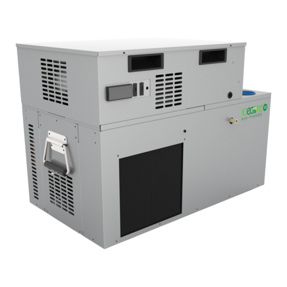
Hyper Warwick R290 + Icecore 10 R290 Installation Manual Original instructions English version – EN Appliance types covered: Model Type 01-3000-xx Hyper Warwick R290 Integral 01-3001-xx Hyper Warwick R290 Water Cooled 11-1000-xx Icecore 10 Integral (Cold Carbonated) 11-1001-xx Icecore 10 Water Cooled (Cold Carbonated) PART No. - Page 2 Installation Manual Dear Customer Please read the User Guide and Installation Manual carefully before operating this unit. Please keep the User Guide and Installation Manual safe and with the unit. Examine the equipment immediately after supply for transport damage. Contact your equipment supplier and/or carrier if necessary. Damage, which arises by inappropriate treatment or operation, is not subject to guarantee / warranty.
-
Page 3: Table Of Contents
Table of Contents Section 1 – Warnings Section 2 – General description and function of the unit Section 3 – Installation & Commissioning 10-23 Section 4 – Maintenance and cleaning 24-27 Section 5 – Spare parts lists 28-32 Section 6 – Wiring schematic 33-37 Section 8 –... -
Page 4: Section 1 – Warnings
Section 1 Section 1 – Warnings WARNING: THIS APPLIANCE CAN BE USED BY CHILDREN AGED FROM 8 YEARS AND ABOVE AND PERSONS WITH REDUCED PHYSICAL, SENSORY OR MENTAL CAPABILITIES OR LACK OF EXPERIENCE AND KNOWLEDGE IF THEY HAVE BEEN GIVEN SUPERVISION OR INSTRUCTION CONCERNING USE OF THE APPLIANCE IN A SAFE WAY AND UNDERSTAND THE HAZARDS INVOLVED. - Page 5 Section 1 BEFORE LIFTING OR MOVING THIS EQUIPMENT IT IS RECOMMENDED THAT ALL PERSONS PERFORMING THESE TASKS SHOULD RECEIVE RELEVANT TRAINING IN SAFE HANDLING. ALL PERSONS LIFTING OR MOVING THIS EQUIPMENT MUST BE WEARING THE CORRECT PERSONAL PROTECTIVE EQUIPMENT. TO PREVENT PERSONAL INJURY WHERE PRACTICAL, TRANSPORTING OF THE UNIT OVER EXTENDED DISTANCES SHOULD BE DONE USING A MECHANICAL AID.
- Page 6 Section 1 APPLICABLE TO R290 UNITS ONLY Warning THIS EQUIPMENT IS CHARGED WITH R290 REFRIGERANT (PROPANE). ONLY QUALIFIED SERVICE ENGINEERS HOLDING A VALID HANDLING CERTIFICATE FOR CARE 40 (PROPANE) CAN WORK ON THE REFRIGERATION SYSTEM OF THIS EQUIPMENT. PLEASE READ THE INFORMATION BELOW BEFORE ANY WORK IS CARRIED OUT. Refrigeration R290 (Care 40, Propane) Note: Only engineers who have been trained in the safe handling and use of hydrocarbon refrigerants should work on this system.
- Page 7 Section 1 THE UNIT. IT IS NOT TO BE USED FOR ANY OTHER PURPOSE TO POWER ANY OTHER MAINS EQUIPMENT. (REFER TO IMAGE ON PAGE 9) WARNING: THE CARBONATOR IS AN INTEGRAL PART OF THE UNIT AND IT SHOULD BE NOTED THAT THE CARBONATION PROCESS INVOLVES THE USE OF HIGH PRESSURE AND POTENTIALLY NOXIOUS GAS.
-
Page 8: Section 2 – General Description And Function Of The Unit
Section 2 Section 2 – General description and function of the unit The Icecore 10 family of remote coolers have been designed to carbonate, recirculate and chill mains potable water and chill soft drinks syrup. This equipment is designed to be installed in cellars, ventilated storerooms and areas generally away from the point of dispense. - Page 9 Section 2 Keep the unit free from excessive heat and cold. Minimum and maximum ambient temperatures are: Minimum: 12°C Maximum: 32°C invalidate any warranty, and may constitute a danger to yourself and others. This cooler has been subjected to a number of thorough quality checks before leaving the factory.
-
Page 10: Section 3 – Installation & Commissioning
Section 3 Section 3 – Installation & Commissioning Unpack the unit from its transportation packing and visually check for any signs of with a 10 amp fuse or alternatively a standard Euro Plug to IEC83: 1975. For both Ambient and Cold Carbonated appliances in the U.K. a WRAS approved mains water connection (for other markets, a none return valve complying with local to interconnect appliances within the system. - Page 11 Section 3 AMBIENT CARBONATED UNITS – CONNECTING THE UNIT TO THE WATER, CO2, PYTHON AND COMMISSIONING. SYRUPS IN SYRUPS OUT CARBONATOR WATER STILL IN STILL OUT SODA IN SODA OUT CONNECTION NOTES SYRUP COILS 1-5: 5/16” PLAIN RINGED ENDS SODA STILL & CARBONATOR WATER LINES 3/8” PLAIN RINGED ENDS 01-3001-01 WATER COOLED NOTE: HEAT DUMP FLOW AND RETURN FITTINGS 15MM (SUPPLIED WITH UNIT) 1.
- Page 12 Section 3 7. If required, connect a mains water supply to the STILL IN connection and the STILL OUTLET connection to the appropriate line within the python. Ensure the outlet line to the python is insulated. 8. Connect the syrup lines within the python to the connections labelled SYRUPS OUT 9.
- Page 13 Section 3 AMBIENT CARBONATED INTEGRAL APPLIANCE CONTROL POSITIONS POWER TO CARBONATOR CARBONATOR POWER 240V 01-3000-01 INTEGRAL BACK CONNECTION DETAILS REAR CONNECTIONS MAINS PUMP POWER INDICATOR INDICATOR (RED) (GREEN) PUMP MAINS PUMP CONTROLLER SODA PUMP ISOLATION SWITCH UP - PUMP OFF DOWN - PUMP ON 01-3000-01 INTEGRAL FRONT SODA ISOLATION SWITCH...
- Page 14 Section 3 AMBIENT CARBONATED WATER COOLED APPLIANCE CONTROL POSITIONS POWER TO POWER TO CARBONATOR GLYCOL MODULE CARBONATOR GLYCOL POWER POWER 240V 240V COOLANT COOLANT RETURN FLOW 01-3001-01 WATER COOLED BACK RE-CIRC RE-CIRC CONNECTION DETAILS RETURN FLOW REAR CONNECTIONS PUMP MAINS INDICATOR POWER INDICATOR (GREEN)
- Page 15 Section 3 COLD CARBONATED UNITS – CONNECTING THE UNIT TO THE WATER, CO2 AND PYTHON AND COMMISSIONING SYRUPS IN SYRUPS OUT STILL STILL SODA 1. If the unit is a water cooled version, the glycol module and heat dump must be installed and connected as detailed in the Glycol module and heat dump installation guidelines before commissioning the complete system.
- Page 16 Section 3 8. If required, connect a mains water supply to the STILL IN connection and the STILL OUTLET connection to the appropriate line within the python. Ensure the outlet line to the python is insulated. 9. Connect the syrup lines within the python to the connections labelled SYRUPS OUT 10.
- Page 17 Section 3 18. Switch the soda recirc pump on and allow the system to make its ice bank and chill the python down. If the fridge unit is to be operated during the installation (i.e. To begin building the ice bank) isolate the soda recirc pump by turning the switch to 19.
- Page 18 Section 3 COLD CARBONATED WATER COOLED APPLIANCE CONTROL POSITIONS GLYCOL POWER 240V COOLANT COOLANT RETURN FLOW POWER TO GLYCOL MODULE GLYCOL POWER 240V COOLANT COOLANT FLOW RETURN RE-CIRC RETURN RE-CIRC FLOW HEAT DUMP INSTALLATION - GENERAL GUIDELINES The guidelines below should be adhered to wherever possible. 2.
- Page 19 Section 3 6. The heat dump must be connected using a minimum of 1.5mm2 two core cable. If a smaller cable is used , a voltage drop will occur which will cause the fan to run at a lower speed. 7.
- Page 20 Section 3 6. Ensure the coolant lines are correctly installed and free from kinks. 7. Fill the glycol module reservoir tank with a quantity of Monopropylene glycol coolant mixed 30% glycol to 70% water, ensuring a quantity remains for topping the system up when priming.
- Page 21 Section 3 WATER COOLED UNIT EQUIPMENT SELECTION SCHEMATIC HEAT DUMP 230V Mains Supply 24 VAC BASE UNIT GLYCOL MODULE 230V Supply Coolant Flow ELECTRONIC CONTROL SETTINGS AND ADJUSTMENT INSTRUCTIONS DFX SERIES 1E CONTROLLER AND PROBE: The controller is electronic, and is supplied with a temperature probe. The Cut-Out and Cut-In temperatures are factory set at Welbilt (Halesowen) Ltd, and should not require any adjustment.
- Page 22 Section 3 1. To adjust the Cut-Out Temperature: A. Carefully remove the lens from the front of the controller. B. Press and hold the button. Release after 2 seconds. C. The display will change from ‘Current Temperature’ to ‘Current Set-Point’. D.
- Page 23 Section 3 corner of the display. This is the Opening Time. I. Adjust the time up or down by using the (+) or (-) buttons. J. When the desired time is displayed, press and release the button again. corner of the display. This is the Closing Time. L.
-
Page 24: Section 4 – Maintenance And Cleaning
Section 4 Section 4 – Maintenance and cleaning • Service & Maintenance of the equipment should only be carried out by Welbilt (Halesowen) Limited. trained, competent, technicians, abiding by all the relevant statutory regulations and industry recommendations. • Before removing the panels from the equipment the mains supply must be disconnected, either by removal of the plug from the wall socket, or in the powered up. - Page 25 Section 4 Cleaning: For the UK please follow the procedure below: BASIC INSPECTION CHECKS BY THE END USER WEEKLY: There is no end user training required on this appliance other than understanding the weekly basic checks for safe unit operation. It is not recommended that the end user makes any adjustments or carries out any maintenance other than: 1.
- Page 26 Section 4 RECOMMENDED LINE CLEANING METHOD Clean and sanitize the cooling coils and product lines at a minimum of every six months using a proprietary cleanser/sanitizer of the Alkaline Hypochlorite type, in accordance with the manufacturer’s recommendations. Welbilt recommends the use of “Pipeline” cleaner, which changes colour according to the condition of the product lines.
- Page 27 Section 4 In the event of Freezing Up occurring, the following action is recommended: 1. Isolate the unit from Mains Electricity Supply. 2. Identify the fault and rectify. 3. Isolate Product Supply from unit and depressurise the system. 4. Apply gentle warmth to the general area of the unit and its Pipe work. 5.
-
Page 28: Section 5 – Spare Parts Lists
Section 5 Section 5 – Spare parts list 01-3000-01 HYPER WARWICK R290 INTEGRAL SPARES PART 1. 01-3000-xx Hyper Warwick Integral BALLOONS REFERENCE SPARE PARTS LIST PAGE #34 01-3000-01 HYPER WARWICK R290 INTEGRAL SPARES PART 1. BALLOONS REFERENCE SPARE PARTS LIST PAGE #34 01-3000-01 HYPER WARWICK R290 INTEGRAL SPARES PART 2. - Page 29 Section 5 01-3001-xx Hyper Warwick Water Cooled 01-3001-01 HYPER WARWICK R290 WATER COOLED SPARES PART 1. BALLOONS REFERENCE SPARE PARTS LIST PAGE #35 01-3001-01 HYPER WARWICK R290 WATER COOLED SPARES PART 1. BALLOONS REFERENCE SPARE PARTS LIST PAGE #35 01-3001-01 HYPER WARWICK R290 WATER COOLED SPARES PART 2.
- Page 30 Section 5 11-1000-xx Icecore 10 Integral (Cold Carbonated) 11-1001-xx Icecore 10 Water Cooled (Cold Carbonated) ICECORE 10 (COLD CARBONATED) PART No. DESCRIPTION PI56613 DFX1E C\W SHORT PROBE PI56242 BI-LEVEL CARBONATOR CONTROL P30 IC10 SPARES PI56363 SLIDER SWITCH PI015558 P-CLIP FOR SECURING PROBE CABLE MO014715 CARBONATOR PUMP MOTOR (230v - RPM 180W) PU70172-00...
- Page 31 Section 5 INTEGRAL FRIDGE WATER COOLED FRIDGE INTEGRAL FRIDGE SPA (P30/31) IC10 INTEGRAL FRIDGE SPARES (11-1000-xx) IC10 INTEGRAL FRIDGE SPARES (11-1000-xx) INTEGRAL FRIDGE SPARES (P30/31) PART No. DESCRIPTION PART No. DESCRIPTION OP74326 CAPACITOR (SECOP REF 117U5017) OP74326 CAPACITOR (SECOP REF 117U5017) OP72923 JOHN GUEST 1/2"...
- Page 32 Section 5 11-1000-xx Icecore 10 Integral (Cold Carbonated) 11-1001-xx Icecore 10 Water Cooled (Cold Carbonated) SEE PAGE 30 FOR INFO ICECORE 10 (COLD CARBONATED) PART No. DESCRIPTION PI43762 JOHN GUEST 3/8 SHUT OFF VALVE MO57312 AGITATOR MOTOR ASSEMBLEY PI47155 BATH FILLER PLUG SG-83-0868 CO2 LOW PRESSURE SWITCH OP73838...
-
Page 33: Section 6 – Wiring Schematic
Section 6 Section 6 – Wiring Schematic 01-3000-xx Hyper Warwick Integral... - Page 34 Section 6 01-3001-xx Hyper Warwick Water Cooled...
- Page 35 Section 6 11-1000-xx Icecore 10 Integral (Cold Carbonated) Wiring Schematic...
- Page 36 Section 6 11-1001-xx Icecore 10 Water Cooled (Cold Carbonated) Wiring Schematic...
- Page 37 Section 6 Iceore 10 Cold Carb Schematic Layout: Hyper Warwick Schematic Layout:...
- Page 38 Section 7 HYPER WARWICK HYPER WARWICK 01-3000-XX / 01-3001-XX INTEGRAL (01-3000-01) WATER-COOLED (01-3001-01) AMBIENT CARB AMBIENT CARB Physical Data Height 445 mm 445 mm Width 762mm (inc. handles) 762mm (inc. handles) Depth 440 mm 440 mm Operating Weight 77.5 kgs 77.5 kgs Max Noise dB(A) 70 dBA...
- Page 39 Section 7 ICECORE 10 ICECORE 10 11-1000-xx / 11-1001-xx COLD CARB (11-1000-xx) COLD CARB (11-1001-xx) INTEGRAL WATER COOLED Physical Data Height 535 mm 535 mm Width 762mm (inc. handles) 762mm (inc. handles) Depth 440 mm 440 mm Operating Weight 87 kgs 87 kgs Max Noise dB(A) 70 dBA...
- Page 40 Section 7 Climate class ISO 23953-2:2005(E) TEST ROOM DRY BULB RELATIVE HUMIDITY DEW POINT WATER VAPOUR MASS CLIMATE CLASS TEMPERATURE IN DRY AIR °C °C g/kg 12.6 15.2 10.8 16.7 14.8 21.1 15.8 23.9 18.8 27.3 23.9 14.3 10.2 NOTE...
-
Page 44: Section 8 – Declaration Of Conformity
2023/2006/EC - Good Manufacturing Practice for Articles in Contact with Food Regulation 1907/2006/EC – REACH Regulation 517/2014/EU – F GAS Regulation 1005/2009/ EC – Ozone depleting substances Regulation Marking of the equipment: 01-3000-xx Hyper Warwick R290 INT 01-3001-xx Hyper Warwick R290 WC 11-1000-xx Icecore 10 Cold Carb R290 INT 11-1001-xx...
Need help?
Do you have a question about the Hyper Warwick R290 and is the answer not in the manual?
Questions and answers