Advertisement
Quick Links
Manufacturer:
Terazidere Mah.60.Yil Cad.No:5/3
34035 Bayrampasa/ISTANBUL/TURKEY
TEL: 0 212 501 48 63
FAX: 0 212 501 48 83
Email:
opkoninfo@opkon.com.tr
ELECTRICAL CONNECTION
Ver 2.0E
USER GUIDE
WARNING!
READ CAREFULLY BEFORE POWER ON
1.
Complete electrical connections according to the
schematic at the last page.
2.
Check Supply Voltage 220V (or 24V optional) AC, or DC, due to
Specifications on the equipment.
3.
Use only shielded cable for sensors.
4.
Keep away the equipment from direct heat source.
5.
MODEL OP-CN4 is not suitable for outdoor use.
6.
Keep away the equipment from water or other liquid
drains.
7.
Do not open, modify or replace any component in the
equipment, If any problem occurs please contact an authorised
OPKON technical service or OPKON directly.
ELECTRICAL SPECIFICATIONS:
Microcontroller based
A /B /Z(Reset)-4 X Counter mode
200 kHz Max. counting frequency
2 X Relays output
1 X SSR output
Incremental or absolute positioning mode
Holding on the last value in memory
10 X Output modes
Offset calibration
Password to protect menus
Power Supply
:220V ± % 20 (or 24V optional) ,50 Hz
Power Consumption
:<4 VA (protected by fuse 50mA)
Sensor supply voltage
:+5V or +12VDC (selectable by jumper)
Sensor supply current
:Max.100mA(no fuse)
Relays max. ratings
:Relay1
Relay2
SSR output
:5V DC (non-isolated)
MECHANICAL SPECIFICATIONS:
Dimensions
:72x72x90 mm
Panel cut dimensions
:67x67mm
Body
:ABS plastic
Working temperature
:0-60 ºC
Storage temperature
:-10ºC ...+80ºC
:<%90 RH
Humidity
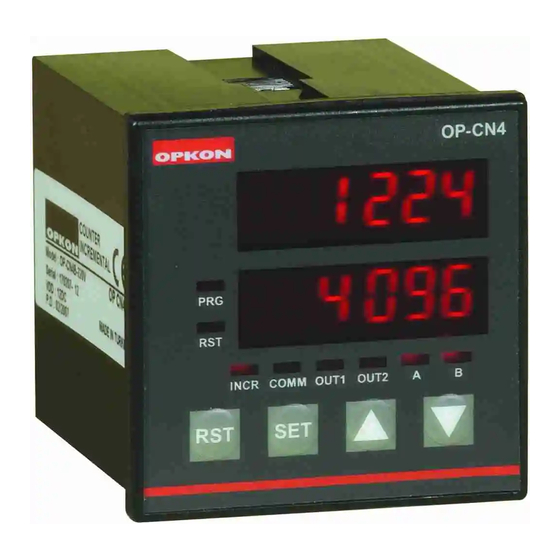
MODEL OP-CN4
UNIVERSAL
INCREMENTAL
COUNTER
1xNO+NC 8A,230V AC
1xNO+NC 8A,230V AC
Advertisement

Summary of Contents for Opkon OP-CN4
- Page 1 Specifications on the equipment. Use only shielded cable for sensors. Keep away the equipment from direct heat source. MODEL OP-CN4 is not suitable for outdoor use. Keep away the equipment from water or other liquid drains. Do not open, modify or replace any component in the equipment, If any problem occurs please contact an authorised OPKON technical service or OPKON directly.
- Page 2 DESCRIPTIONS MODEL OP -CN4 OUTPUT TYPES BUTTONS 1. Resets the counter. 2. Escapes from program menu. COUNTER DISPLAY 1. Enters to program menu. 2. Shifts the rows When programming parameters PARAMETER DISPLAY 1. Travels in menu. 2. Changes the program LED INDICATORS Turns on when equipment programming Indicates Communication RS232(optional).
- Page 3 11. dSPtyP This parameter defines screen format.Available 3 states; • Press SET button to enter the submenu When stay on dSPtyP • Please refer to " enterring the CodE." • Press . UP/DOWN buttons and select one of this condition. 1.
- Page 4 SUBMENU SETTINGS 6. toUt2 This parameter is used to keep in active durationof the RELAY2 in seconds(s). Sample: For 1.4 second 1. SEt1 duration of RELAY2; SEt1 is the value of Relay1 turns active. (please refer to tOut1 for duration of activation of Relay1). •...
Need help?
Do you have a question about the OP-CN4 and is the answer not in the manual?
Questions and answers