
Summary of Contents for Warner ERS VAR10 SZ 2500
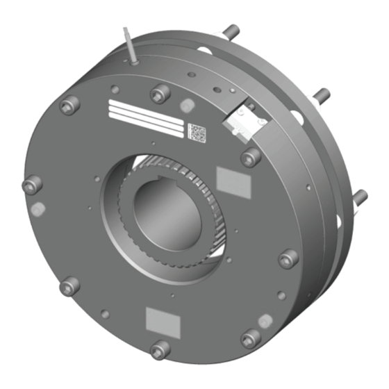
- Page 1 Electrically Released Brake ERS VAR10 SZ 2500 Service & Installation Instructions P-2107-WE-A4 SM477GB...
-
Page 2: Table Of Contents
- D _ ______________________________________________________________________ 12 ISCS EXCHANGE - D ___________________________________________________________________ 12 ETECTION HECKING - D _ ____________________________________________________________________ 13 ETECTION SETTING - M ________________________________________________________________ 13 ICROSWITCH EXCHANGE SPARE PARTS _ _____________________________________________________ 1 4 TOOLING _________________________________________________________ 1 4 TROUBLESHOOTING ________________________________________________ 1 5 CONTACT _________________________________________________________ 1 5 WARNER ELECTRIC EUROPE - Rue Champfleur, B.P. 20095, F - 49182 St Barthélemy d’Anjou Cedex SM477gb - rev 04/16 2/15... -
Page 3: Eu Declaration Of Conformity
Safety rules for the construction and installation of lifts – Lifts for the transport of persons and goods – Parts 20: Passenger and goods passenger lifts. EN 81-50:2014 Safety rules for the construction and installation of lifts – Examinations and tests – Parts 50: Design rules, calculations, examination and tests of lift components. DIN VDE 0580:2011 Electromagnetic devices and components, General requirements. EN ISO 12100:2010 Safety of machinery – General principles for design – Risk assessment and risk reduction. 2- Precautions And Safety Measures Precautions and safety measures must be read before any installation or maintenance of the brake. Compliance with the instructions and values given by the documentation and marking of the unit is imperative in order to ensure a proper functioning of the brake. 2.1 - Symbols used in this manual Action that might damage the brake. Action that might be dangerous to human safety. Electrical action that might be dangerous to human safety. Handling of loads that might be dangerous to human safety. Surface temperature that might be dangerous to human safety. WARNER ELECTRIC EUROPE - Rue Champfleur, B.P. 20095, F - 49182 St Barthélemy d’Anjou Cedex SM477gb - rev 04/16 3/15... -
Page 4: Safety Precautions For Installation And Maintenance
Move to fresh air in case of accidental inhalation of dusts. In the event of persistent symptoms receive medical treatment. In case of ingestion of friction material dust, consult a doctor. Provide appropriate exhaust ventilation at places where friction material dust can be generated. Do not use brushes, pressurized air or hazardous agents to clean the brake. The use of a vacuum cleaner is recommended. Hand protection Protective and dust-resistant gloves. Eyes protection Friction material dust particles, like other inert materials, may be mechanically irritating the eyes. Safety goggles with side protection. In case of contact with eyes, carefully rinse with plenty of water. In the event of persistent symptoms seek medical treatment. Skin protection Prolonged skin contact may cause mechanical irritation. Dust resistant protective clothing. In case of contact with skin, wash with soap and water as a precaution. Consult a doctor if skin irritation persists. Feet protection Safety shoes must be worn. WARNER ELECTRIC EUROPE - Rue Champfleur, B.P. 20095, F - 49182 St Barthélemy d’Anjou Cedex SM477gb - rev 04/16 4/15... -
Page 5: Precautions For Handling
This brake is designed to work in clean conditions. Friction faces must be kept completely clean of any oil, water, grease or abrasive dust. The friction flange, on customer side, must be, also, carefully cleaned and degreased. The friction faces must be protected, with adapted devices (cover, heating devices, etc…): • To avoid pollution and rusting during the lifetime of the unit. • To avoid condensation, resulting in freezing conditions, in low temperature/high humidity, or sticking of the disc. This brake is designed to work in ambient temperature between 0°C and 40°C. This brake is designed to work with duty cycle of 50% (Insulation class: 155°C). The temperature of customer friction flange must not exceed 90°C. This brake can only be used on « horizontal » position. When switching on DC-side the coil must be protected against voltage peaks, according DIN VDE0580. Make sure the rated supply voltage is set within the tolerances, an under-voltage supply, generates a reduction of the maximum air gap. An over-voltage supply generates additional heat on the surface of the brake, with risks of injury by burning and possible damage to the coil. WARNER ELECTRIC EUROPE - Rue Champfleur, B.P. 20095, F - 49182 St Barthélemy d’Anjou Cedex SM477gb - rev 04/16 5/15... -
Page 6: Restrictions On Use
Service braking: for service braking, the switching OFF and ON must be connected on AC current side, in order to obtain silent switching. 2.5 - Restrictions on use Any modification made to the brake without the express authorisation of a representative of Warner Electric, as far as, any use out of the contractual specification accepted by "Warner Electric", will result in the warranty being invalidated and Warner Electric will no longer be liable in any way with regard to conformity. If maximum rotation speed is exceeded, the guarantee is no longer valid. The brake must be replaced it is submitted to water projections. - Page 7 Torque installed 2200 2500 3000 Overexcitation voltage Vdc 207 207 103,5 48 207 Holding voltage Vdc 103,5 103,5 103,5 Overexcitation power Watt 315 315 232 273 315 Holding power Watt Maximum speed min-1 250 Minimum Air gap 0,4 Maximum Air gap (after wear) 0,7 Cyclic duration factor 60% Weight * Brakes produced from 20 April 2016 ** Brakes produced until 19 April 2016 WARNER ELECTRIC EUROPE - Rue Champfleur, B.P. 20095, F - 49182 St Barthélemy d’Anjou Cedex SM477gb - rev 04/16 7/15...
-
Page 8: Labeling Details
Data Field Product name Release (NA) Revision (NA) Identification number Serial number Batch number (NA) Manufacturer name Manufacturer postal code Manufacturer town Manufacturer country code Encoded date details: Day M Production day Encoded year: 1 letter Encoded month: 1 letter 2006 2007 2008 2009 2010 2011 2012 2013 2014 2015 2016 2017 Angl 2018 2019 2020 2021 2022 2023 Example: YN16 is, 2010, 16th February WARNER ELECTRIC EUROPE - Rue Champfleur, B.P. 20095, F - 49182 St Barthélemy d’Anjou Cedex SM477gb - rev 04/16 8/15... -
Page 9: Installation
Caution: When installing and should the brake ever be taken apart, make sure that the friction disc heel is the right way round when the brake is put back together (see Fig.1). Engage the rear disc the heel on the brake side with the intermediate disc and the brake on the hub. Line the brake up with the customer fixing flange, using the fixing screws. NOTE: Secure the fixing screws (safety washer or a thermoplastic liquid such as Loctite). Tighten the 8 fixing screws CHc M12, star sequence tightening, to an initial torque of 50 Nm. The supply of current to the brake should be switched off. Switch on current to the magnet. Tighten the 8 fixing screws CHc M12(Cs: 130 Nm ±10%). The supply of current to the brake should be switched on throughout this operation. Remove the three transport screws. Make all the permanent electrical connections WARNER ELECTRIC EUROPE - Rue Champfleur, B.P. 20095, F - 49182 St Barthélemy d’Anjou Cedex SM477gb - rev 04/16 9/15... -
Page 10: Electrical Connection
The connecting wires must be thick enough to help prevent sudden drops in voltage between the source and the brake. Cable length 0 -> 10 10 -> 20 Cross section mm² 1.5 2.5 Table 2 Tolerances on the supply voltage at the brake terminals: +10% / -15% (CEI 60038:2009:2009-06). 6.1 - Microswitch Technical Data Microswitch connection Switch Connection Black (NC) Brown Blue (NO) Current range: 10 mA à 100 mA at 24 Vdc § For maximum electrical lifetime of the microswitch ensure switching under resistive load § only. WARNER ELECTRIC EUROPE - Rue Champfleur, B.P. 20095, F - 49182 St Barthélemy d’Anjou Cedex SM477gb - rev 04/16 10/15... -
Page 11: Maintenance
Under no circumstances, this device can replace the system case against the car overspeed in the descending phase. Air gap has to be measured at the 4 points at the circumference and at each braking circuit (see Fig. 3). If the maximum value of the air gap (see Table 1) is exceeded in one point, change the disc and the O-ring. Do not introduce the feeler gauge more than 10 mm into the air gap. Avoid the springs and the dampers of noise. Any modification made to the brake without the express authorisation of a representative of Warner Electric, as far as, any use out of the contractual specification accepted by "Warner Electric", will result in the warranty being invalidated and Warner Electric will no longer be liable in any way with regard to conformity. The customer must be careful to not alter the factory set parameters: Microswitch adjustment, air gap adjustment and dampening system. This brake must not be dismantled. Loosen the fixing screws slightly. Slide into the airgap 4 feeler gauges 0,45 mm thick, or according Fig. 3a (put the feeler gauges near the marks on the magnet). -
Page 12: Discs Exchange
This brake is designed to work in clean conditions. Friction faces must be kept completely clean of any oil, water, grease or abrasive dust. Customer friction flange must be also carefully cleaned. Disconnect the brake electrically Remove the fixation screws Remove the brake Clean the friction faces with a clean and dry cloth. After the worn friction disc is replaced, assemble the brake according chapter 5.2. 7.3 - Detection Checking Any modification made to the brake without the express authorisation of a representative of Warner Electric, as far as, any use out of the contractual specification accepted by "Warner Electric", will result in the warranty being invalidated and Warner Electric will no longer be liable in any way with regard to conformity. The customer must be careful to not alter the factory set parameters: Microswitch adjustment, air gap adjustment and dampening system adjustment. This brake must not be dismantled. Switch ON the brake, the state of both microswitches must change. Switch OFF the brake. Insert a feeler gauge 0.2 mm in the nearest control zone of the microswitch. Switch ON the brake, the state of both microswitches must not change. WARNER ELECTRIC EUROPE - Rue Champfleur, B.P. 20095, F - 49182 St Barthélemy d’Anjou Cedex SM477gb - rev 04/16... -
Page 13: Detection Setting
All intervention must be done by authorized and qualified personnel, having read and understood this manual, using adapted procedures and professional tools. All intervention must be done according the regulation of the country of the installation. Warning: not to damage the electric cables during the maintenance action. Unplug the microswitch Remove the microswitch fixing screws Replace the microswitch Tighten the fixing screws to the torque of 0.8 N.m (±10%) Re-connect microswitch wires (see chapter 6.1) Set the detection as it is shown in the chapter 7.4 Fig. 5 WARNER ELECTRIC EUROPE - Rue Champfleur, B.P. 20095, F - 49182 St Barthélemy d’Anjou Cedex SM477gb - rev 04/16 13/15... -
Page 14: Spare Parts
8- Spare parts Available spare parts for this brake are the following: Friction disc Microswitch O-ring Kit Please, join to your spare part request the following information: • Warner Electric Europe Reference • Production Number • Serial Number • Production Date Production N° Sérial N° 207/103VDC 88/21 W 777888-1 303xxxxx Warner Electric Europe Reference Production Date 9- Tooling WARNER ELECTRIC EUROPE - Rue Champfleur, B.P. 20095, F - 49182 St Barthélemy d’Anjou Cedex SM477gb - rev 04/16 14/15... -
Page 15: Troubleshooting
Troubleshooting Contact Any question? You can contact us at: This translation is for information only. In case of discrepancy between this version and the original in French, only the text of the French version prevails. All rights reserved to change without prior notice. WARNER ELECTRIC EUROPE - Rue Champfleur, B.P. 20095, F - 49182 St Barthélemy d’Anjou Cedex SM477gb - rev 04/16 15/15... - Page 16 www.warnerelectric-eu.com Rue Champfleur, B.P. 20095 F- 49182 St Barthélemy d’Anjou Cedex +33 (0)2 41 21 24 24 P-2107-WE-A4 SM477GB 9/18...
Need help?
Do you have a question about the ERS VAR10 SZ 2500 and is the answer not in the manual?
Questions and answers