Table of Contents
Advertisement
Advertisement
Table of Contents

Subscribe to Our Youtube Channel
Related Manuals for Festo MecLab

Summary of Contents for Festo MecLab
- Page 1 Festo Learning Systems MecLab Getting Started...
- Page 2 F. Zierau Copyright 2008 This document and its contents are the property of Festo Corporation. No part of this document may be reproduced, utilized, transmitted or disclosed in any form or by any means without prior written consent of Festo Corporation Festo Corporation 395 Moreland Rd.
-
Page 3: Table Of Contents
Table of Contents Introduction Course Objectives Safety Training Systems Operations Overview Commissioning Sample Programs Safety and Maintenance Stack Magazine Station Conveyor Station Handling Station Lesson Planning Projects © 2008 Festo Corporation... -
Page 4: Introduction
The topics cover basic components used in in- dustrial automation. It also provides exercises for developing pneumatic and electrical sche- matics using FluidSim-P software. Overall the topics are intended to prepare the student to study more advanced systems. © 2008 Festo Corporation... -
Page 5: Course Objectives
• Familiarization with industrial component symbols and designations. • Understand the term “sequence of operations”. • Become familiar with pneumatic and electrical schematics. • Understand control of linear actuators. • Understand principles of relays. • Understand limit switches. © 2008 Festo Corporation... -
Page 6: Safety
Additionally, Festo Corporation assumes no re- sponsibility for the safe and/or satisfactory operation of any machine. sponsibility for the safe and/or satisfactory operation of any machine. *See also page 7, “Operation of the Festo Training System,” for additional safety considerations. © 2008 Festo Corporation... - Page 7 Operation of the Festo Training System Festo training systems have been designed for ease of use by both the student and the in- structor. Compressed air should be handled with respect. Care should be taken to ensure that com- pressed air is not directed at open cuts or against the skin, since serious physical damage and/or dangerous embolism may result.
- Page 8 © 2008 Festo Corporation...
-
Page 9: Overview
They must be able to disassemble and assemble a system. MecLab®, developed by Festo Learning Systems, includes a stack magazine, a conveyor and a handling station. These simulate parts of an automated production line. It is designed to familiarize students with automated technical systems. - Page 10 − Video − Technical drawings − Diagrams The combination of theory and practice is an essential aspect of MecLab® and its compo- nents. For every theory related to engineering sciences, there is a corresponding applica- tion. The connection between theory and practice will encourage students to put in to practice what they have learned.
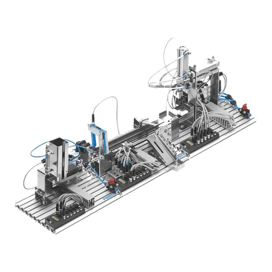
- Page 11 Getting Started with Festo MecLab Overview The MecLab® learning system consists of three stations that carry out the following func- tions: − Storage and separating − Transporting (conveying) − Handling. These three processes are typical for all automated production. Figure 2.1 shows a production line that manufactures formed sheet metal parts. The material is transported by means of a roller conveyor (3) to the machining stations (1, 2, 7), where it is shaped.
- Page 12 PC. The software contains sample programs designed to help the student “get started” with pro- gramming. Since the Meclab system is made of industrial components, it is also possible to perform “manual override” operations. Students are encouraged to use the provided tools to disassemble and reassemble the sta- tions.
- Page 13 The Meclab system consists of the following: − 1 compressor for supplying the stations with compressed air − 6 licenses of FluidSIM for MECLAB® simulation and control program − 3 modified EasyPorts for connecting the stations to a PC − 3 power supply units for supplying power to the EasyPort −...
-
Page 14: Commissioning
"setup.exe" file and follow the installation instructions. Assemble the stations MecLab® stations are delivered assembled. To commission a station, perform the following steps: − Insert the EasyPort interface module (1) to the Sub-D socket on the multi-pin plug distribu- tor (2). -
Page 15: Sample Programs
The FluidSim software contains sample programs to help the Instructor and the student get started in programming the MecLab stations. These samples are located in the “ct file\MecLab Samples. Use these files to become familiar with how the software and the hard- ware operate. -
Page 16: Safety And Maintenance
Getting Started with Festo MecLab Safety and Maintenance MecLab® has been designed in compliance with all relevant safety guidelines. As with all technical systems, there is additional safety information that must be observed. General Students must be supervised at all times when working on the stations. - Page 17 − Do not place your hand in the station while it is running. Maintenance information MecLab® is essentially maintenance-free. Wipe occasionally with a dry, lint free rag. Water must be drained from the compressor tank or water separator (at the regulator) at regular intervals.
-
Page 18: Stack Magazine Station
Getting Started with Festo MecLab Stack Magazine Station Virtually all automated production requires the temporary storage of raw material, semi- finished product or finished product. Often the material is kept on pallets or in warehouses. At some point the material (or parts) will be brought to the production line. It is here that the work pieces must be organized in such a way that they can be fed into the production proc- ess as quickly and efficiently as possible. - Page 19 Getting Started with Festo MecLab Stack Magazine Station Delicate work pieces are generally supplied in an organized manner. Smaller work pieces are often stored on tape while larger work pieces are stored on pallets (Figure 4.2 shows in- tegrated circuits (ICs) on a pallet, normally called a tray in the electronics industry).
- Page 20 Getting Started with Festo MecLab Stack Magazine Station Although not necessary, a basic knowledge of CAD/CAM programs is helpful when using the FluidSIM software. The software, in turn, can be useful in learning: − The function of simple electro-pneumatic circuits.
- Page 21 Getting Started with Festo MecLab Stack Magazine Station The following table lists the most important components of the Stack magazine station to- gether with their circuit symbol. Component Symbol Function Mounting kit for proximity sensors Magnetic proximity sensor for detecting the position of...
- Page 22 Getting Started with Festo MecLab Stack Magazine Station Component Symbol Function 4/2-way solenoid valve, with pneu- matic spring return 4/2-way double solenoid valve Multi-pin plug distributor for con- necting the electrical components © 2008 Festo Corporation...
- Page 23 Getting Started with Festo MecLab Stack Magazine Station Assembly and Wiring Several lessons require the student to disassemble and then reassemble the system. Follow the instructions in this section. An aluminum profile plate is used as a base in order to mount the components of the stack magazine.
- Page 24 Getting Started with Festo MecLab Stack Magazine Station Assembling the 4/2-way double solenoid valve 1. Shut off compressed air supply and electrical power. 2. Loosen the retaining screws that connect the valve to the valve retainer. 3. Remove the two short screws and replace with the longer screws.
- Page 25 Getting Started with Festo MecLab Stack Magazine Station It is also possible to install a sensor for checking the end position of the double acting cylin- der. This ensures that the overall sequence is monitored and enables the next step in the se- quence.
- Page 26 Getting Started with Festo MecLab Stack Magazine Station Converting the 4/2-way solenoid valve This shows normal use of a 4/2 directional control valve to control a double acting cylinder. All ports are used (1,2,3 and 4). This shows a 4/2 directional...
- Page 27 Getting Started with Festo MecLab Stack Magazine Station a) 4/2-way solenoid valve (normal use in combination with a double-acting cylinder) b) 3/2-way solenoid valve normally closed (in combination with a single-acting cylinder; port 2 is “plugged”) c) 3/2-way solenoid valve, normally open (in combination with a single-acting cylinder;...
- Page 28 Getting Started with Festo MecLab Stack Magazine Station Sample exercise using the stack magazine The purpose of this section is to explain the interaction of the FluidSIM® software and the hardware components of the stack magazine station using a sample exercise.
- Page 29 Getting Started with Festo MecLab Stack Magazine Station Slot Assignment Label Sensor Valve solenoid Valve solenoid Valve solenoid Table 4.1: Pin allocation for the stack magazine station The following are the steps necessary to launch and configure the control software: Step 1: Launch the FluidSIM®...
- Page 30 Getting Started with Festo MecLab Stack Magazine Station Step 2: Create the pneumatic circuit diagram The components needed to create the pneumatic circuit diagram are located in the library on the left side of the screen. Insert each component by: −...
- Page 31 Getting Started with Festo MecLab Stack Magazine Station The one-way flow control valves should be rotated to ensure straight flow paths. Right-click on the symbol and select “Rotate” and then "270°" in the context menu. Figure 4.10: Rotating the one-way flow control valves Next “plumb”...
- Page 32 Getting Started with Festo MecLab Stack Magazine Station To link valve solenoids with the electrical circuit simply label the valve solenoid symbol (in the pneumatic diagram) with the same label as the solenoid coil symbol (in the electrical dia- gram).
- Page 33 Getting Started with Festo MecLab Stack Magazine Station Step 3: Simulate the pneumatic circuit diagram Start the simulation by clicking on the “Start” button. Left-clicking on the left or right manual override will extend or retract the cylinder. Figure 4.13: Simulating the pneumatic circuit diagram...
- Page 34 Getting Started with Festo MecLab Stack Magazine Station Step 4: Create an electrical circuit diagram Select the symbols in the “component library” under the subcategory “Electrical Controls” in the column on the left. Left click, hold and drag each component to the right side of the program window (the white area) release the left mouse button and component will appear on the white field.
- Page 35 Getting Started with Festo MecLab Stack Magazine Station This produces a circuit diagram like that shown in Figure 4.15. Figure 4.15: Wiring of the electrical circuit Remember to assign the same label to the components that are located in both the electrical schematic and the pneumatic diagram (for example the “valve”...
- Page 36 Getting Started with Festo MecLab Stack Magazine Station Step 5: Simulate the entire circuit Pressing the start button executes the simulation in FluidSIM®. This is an easy and safe way of testing the operation of the electrical and pneumatic circuits.
- Page 37 Getting Started with Festo MecLab Stack Magazine Station Step 6: Perform test with the stack magazine station Note: Please observe all safety regulations when station is supplied with compressed air and elec- trical power. The “real” cylinder will extend if the symbol for the multi-pin plug distributor is inserted in the FluidSIM®...
- Page 38 Getting Started with Festo MecLab Stack Magazine Station Labels in the symbolic multi-pin plug distributor must be assigned. Open the symbol by dou- ble-clicking on it (Figure 4.19). Labels are then assigned as per Table 4.1. The labels must match those used in the pneu- matic and electrical circuit diagrams.
- Page 39 Getting Started with Festo MecLab Stack Magazine Station Figure 4.19: Dialog box for the multi-pin Figure 4.20: Dialog box for the multi-pin plug distributor (default settings) plug distributor with labels set © 2008 Festo Corporation...
-
Page 40: Conveyor Station
Getting Started with Festo MecLab Conveyor Station Conveyors are technical systems that are used in industry for the production (mainly trans- port) of material. Conveyors are used in everyday life. Supermarkets use conveyors for groceries at cash reg- isters and department stores use conveyors in the form of escalators for the convenience of their customers. - Page 41 Getting Started with Festo MecLab Conveyor Station The conveyor station can be used as one of three processes in a production assembly line or as a stand-alone single unit. The following assumes that the conveyor is to be used as a stand-alone unit.
- Page 42 Getting Started with Festo MecLab Conveyor Station Illustration Symbol Description Inductive sensor. Senses metal or metal-coated work pieces. Optical sensor. Detects any work pieces that breaks the beam of light (any non-transparent item). Relay. Activates the mo- tor. Can be used to re- verse the polarity of the motor (reverse direction).
- Page 43 Getting Started with Festo MecLab Conveyor Station Assembly and wiring The conveyor station is supplied assembled. In order to commission the system, the station must be connected to the USB port of the PC using the EasyPort as well as to the power sup- ply using the 24V power supply unit as described in Section 3.
- Page 44 Getting Started with Festo MecLab Conveyor Station Solution The solution involves four steps: 1. Create the mechanical setup 2. Create the circuit diagrams and programming in FluidSIM® 3. Test the program via simulation 4. Test the program with the conveyor station Step 1: Create the mechanical setup Figure 5.2: Schematic diagram of the conveyor...
- Page 45 Getting Started with Festo MecLab Conveyor Station Note: In electrical circuit diagrams sensors are normally indicated with an "S" and relays with a "K". Step 2: Create the circuit diagrams and programming in FluidSIM® − Launch FluidSIM® − Double-click with the left mouse button on the FluidSIM® icon to access the start page of the program.
- Page 46 Getting Started with Festo MecLab Conveyor Station Symbol Designation Function Multi-pin plug distribu- Establishes the con- nection with the Hardware. Labels must match between this device and the la- bels on the actuators sensors in the Fluid- SIM® program. Priority active...
- Page 47 Getting Started with Festo MecLab Conveyor Station Symbol Designation Function Motor, DC Drives the conveyor. Switched on and off using relays. Switch For manual interven- tion in the program. Sensor (optical) The connections on the top and bottom are for the power supply.
- Page 48 Getting Started with Festo MecLab Conveyor Station Figure 5.3: Workspace of FluidSIM® with all the required components Figure 5.4: Wiring of the components © 2008 Festo Corporation...
- Page 49 Getting Started with Festo MecLab Conveyor Station Note: Mistakes can be erased by simply clicking on the component, wiring etc., and pressing the "Delete" button. − Assign labels. Labels must be assigned in order for the FluidSIM® software to “link” the components that belong together.
- Page 50 Getting Started with Festo MecLab Conveyor Station Figure 5.6: Assigning labels (2) Figure 5.7: Circuit with assigned labels © 2008 Festo Corporation...
- Page 51 Getting Started with Festo MecLab Conveyor Station − Link the logic modules in the digital module. To enter the logic program in the digital mod ule or the PLC (programmable logic controller): − Open the digital module by double-clicking on it. A new window containing the digi- tal module's input and output channels will be displayed.
- Page 52 Getting Started with Festo MecLab Conveyor Station As mentioned earlier the following functions are required: − The motor is to start when a pushbutton is actuated (therefore a latching circuit is re- quired to “store” or “remember” the pushbutton signal.
- Page 53 Getting Started with Festo MecLab Conveyor Station Step 3: Test the program To start the simulation, the window of the digital module must be closed. − Click on the arrow on the tool bar at the top of the window.
- Page 54 Getting Started with Festo MecLab Conveyor Station Step 4: Test program via hardware − Insert the symbol for the multi-pin plug distributor in the program (cf. Figure 5.11). Figure 5.11: Program with multi-pin plug distributor − Assign labels to the connection points on the distributor.
- Page 55 Getting Started with Festo MecLab Conveyor Station Figure 5.12: Multi-pin plug distributor dialog box before and after setting the labels The labels must match those used in the electrical circuit diagram. The distributor can then establish the connection to the station. Remember, it is not important what you call the com- ponents.
-
Page 56: Handling Station
Robots are also expensive therefore simpler, less expensive handling devices are normally used for many assembly tasks. Figure 6.1: Industrial robot (picture by Festo Didactic) The following data is important and normally provided by manufacturers of handling devices: − Number of axes −... - Page 57 Getting Started with Festo MecLab Handling Station The most important component in a handling device is the gripper. It is this device that makes contact and manipulates the work piece. The two most common grippers are me- chanical and Vacuum: −...
- Page 58 Getting Started with Festo MecLab Handling Station Components of the handling station The handling station consists of : 1. Two pneumatic linear axes 2. One pneumatic gripper 3. Three valves for controlling the pneumatic actuators 4. Four magnetic proximity sensors for detecting the position of the axes and other compo- nents.
- Page 59 Getting Started with Festo MecLab Handling Station Illustration Symbol Description One way flow control valve. Used to regulate the speed of pneumatic drives. 4/2 directional control valve, solenoid operated with air spring return. 4/2 directional control valve, double solenoid. Multi pin plug distributor.
- Page 60 1. Transferring a work piece 2. Joining the base and lid 3. Sorting or assembly functions in conjunction with other MecLab® stations. The handling station uses a mechanical two-jaw gripper that has been adapted to the cylindrical work piece. This gripper can be exchanged for a vacuum gripper that is avail- able as an accessory.
- Page 61 Getting Started with Festo MecLab Handling Station Executing a simple task using the handling station In a production line, the handling station often carries work pieces between two stations. The following sample exercise explains the step by-step operation of the FluidSIM® software...
- Page 62 Getting Started with Festo MecLab Handling Station Initial considerations: 1. Schematic diagram or drawing of the handling system. Always have a drawing or diagram of the mechanical setup in order to identify the position of sensors valves and actuators. One possible diagram of the components involved in the task could look something like Figure 6.3.
- Page 63 Getting Started with Festo MecLab Handling Station Slot Assignment Description Sensor for cylinder extended position Sensor for cylinder retracted position Valve solenoid (extend cylinder) Valve solenoid (retract cylinder) Table 6.1: Assignment table for the handling station Analysis of the task Before programming, you should be clear about the task.
- Page 64 Getting Started with Festo MecLab Handling Station Circuit diagram creation and programming using FluidSIM® The supplied FluidSIM® software is used for programming. This enables the circuit to be simulated on the computer. If the simulation does not reveal any errors, then the station can be directly activated and operated with the program.
- Page 65 Getting Started with Festo MecLab Handling Station The pneumatic system consists of : 1. One double-acting cylinder 2. One 4/2-way double-solenoid valve 3. Two one-way flow control valves 4. One compressed air supply Figure 6.5 shows the components in the workspace.
- Page 66 Getting Started with Festo MecLab Handling Station Step 3: Rotate the one-way flow control valves The one-way flow control valves should be rotated to produce straight flow paths. Right-click on the symbol. In the context menu that opens, select menu item "Rotate" followed by "270°".
- Page 67 Getting Started with Festo MecLab Handling Station Step 4: Install tubing between components Drag the mouse over a the node point of a symbol until a crosshair is displayed. With the left mouse button pressed, move to the node point of the next symbol. Release the left mouse but- ton as soon as the crosshair symbol appears.
- Page 68 Getting Started with Festo MecLab Handling Station Step 5: Set labels and insert proximity sensors Labels need to be assigned in order for the software to link the symbols. This will also ensure the operation of external hardware via the software program. All components that are used in both the electrical and pneumatic circuit drawing must be labeled.
- Page 69 Getting Started with Festo MecLab Handling Station Figure 6.9: Labeling proximity sensors Step 6: Test the pneumatic circuit Start the simulation by clicking on the Start button (this is the arrow button at the top tool bar). If one of the two manual overrides is clicked on, the valve switches position and the cyl- inder will either extend or retract.
- Page 70 Getting Started with Festo MecLab Handling Station Step 7: Components and wiring of the electrical circuit Electrical components are inserted and connected in the same manner as the pneumatic components. The workspace should look something like figure 6.11 upon completion: Figure 6.11: Inserting and wiring the electrical components...
- Page 71 Getting Started with Festo MecLab Handling Station Step 8: Assign labels To link electrical and pneumatic components, the electrical components must be labeled. This is done the same way as the pneumatic components, i.e. by right-clicking on the compo- nent and entering the labels in an input window. Labels are necessary for the valve solenoids and the sensors.
- Page 72 Getting Started with Festo MecLab Handling Station Step 9: Create the control program The figure below is a control module. It is called a “Logic Module” in the FluidSim library. 24V I1 I2 I3 I4 I5 I6 0V Q1 Q2 Q3 Q4 Q5 Q6 Q3 Q4 Q5 Q6 In order to “write”...
- Page 73 Getting Started with Festo MecLab Handling Station The task requires that the cylinder retract or extend when the respective pushbutton is pressed and the cylinder has reached the relevant end position: 1. Valve solenoid 1M1 is switched on when pushbutton S1 and proximity sensor 1S1 are ac- tuated.
- Page 74 Getting Started with Festo MecLab Handling Station igure 6.15: Complete logic program Testing the solution via simulation Start the simulation by clicking on the Start button (the arrow button on the toolbar). Press pushbutton S1 . The cylinder should extend. Press pushbutton S2. The cylinder should retract.
- Page 75 Getting Started with Festo MecLab Handling Station Testing the solution on the handling station To connect the handling station to FluidSIM®, the EasyPort must be plugged into the multi-pin plug distributor on the station, to the pc (using the USB cable) and to the power supply.
- Page 76 Getting Started with Festo MecLab Handling Station The program can then be built upon to include the other actuators and sensors that are on the station. The schematic diagram, the circuit diagram and the logic program form the technical docu- mentation for the project.
-
Page 77: Lesson Planning
Teaching with Meclab (Commissioning instructions) (this manual) The commissioning instructions consist of an introduction and detailed step-by-step instruc- tions on how to assemble and commission the three MecLab® stations. We recommend that you follow the instructions contained in this document. - Page 78 FluidSIM® Programming and Simulation Software The FluidSIM® programming and simulation software on the supplied CD-ROM is tailored to the functions of MecLab®. The software is easily installed on the PC from the CD-ROM. © 2008 Festo Corporation...
- Page 79 Getting Started with Festo MecLab Lesson Planning Lesson Design MecLab® should be used to teach programming as well as mechanical makeup, setup and conversion of automated systems. Lessons can be divided into three phases: 1. Preparation 2. Project 3. Follow-up and Assessment.
- Page 80 Which components were also present in the actual production facility? Group work MecLab® is designed for project-based teaching in small groups. The recommended group size is 2 students for each station (they will also need a PC with the supplied FluidSIM® soft- ware).
- Page 81 Getting Started with Festo MecLab Lesson Planning Table 7.1: Content of the sample exercises Alternate Training Methods Training is ineffective when more than 3 students are assigned to a work station. As an alternative the students can work through the worksheets, create and test their solu- tions in FluidSIM®.
- Page 82 Getting Started with Festo MecLab Lesson Planning Follow-up and assessment Upon completion of each project exercise the students should be encouraged to reflect on what they have accomplished. As part of this process students should conduct a presenta- tion on what they have learned about the operation of the stations, the sensors, actuators and control algorithms used in the stations.
- Page 83 Getting Started with Festo MecLab Lesson Planning Changing or modifying the stations This is done by either adding components or by modifying programs. For example: Empty magazine warning on the stack magazine station. • − Use a through-beam sensor to monitor parts in the magazine.
- Page 84 Getting Started with Festo MecLab Lesson Planning Figure 7.1: Conveyor with stopper Figure 7.2: Conveyor with stamping function function © 2008 Festo Corporation...
- Page 85 Getting Started with Festo MecLab Lesson Planning Combining stations to form a production line In this exercise, students must solve interfacing problems. The components must be aligned to provide a “handover” or “transfer” of the work piece. There must also be a data link be- tween the stations.
-
Page 86: Projects
Getting Started with Festo MecLab Projects Objectives of the Project Lesson For students the project itself is the goal towards which all actions are directed. For the teacher, it is a way of encouraging students to work on their own (e.g. planning, executing and evaluating). - Page 87 Getting Started with Festo MecLab Projects Encourages Self-organization, personal responsibility and planning Students should work on their own as much as possible during the project lesson. This will enable them to plan, execute and evaluate their work. The teacher acts as a moderator, ob- server and, when needed, an advisor.
- Page 88 Getting Started with Festo MecLab Projects Problem Solving Processes An important characteristic of the project lesson is the process by which the problem is solved. In order to meet the objective the student moves from task preparation to problem solving relying on previously learned knowledge and expertise while also gaining new skills and abilities.
- Page 89 Getting Started with Festo MecLab Projects Deciphering and Understanding the Problem (preparatory phase) This preparatory or informational phase deals with problem definition. In other words stu- dents consider the project goals and establish the steps or tasks. The project goal must be defined.
- Page 90 Getting Started with Festo MecLab Projects Evaluating the Problem Solution (presentation phase) In the presentation phase, the members of the project subgroups present the results of their work to the entire project team or class. In addition to presenting the product of their activity (e.g.finished controller), each group should also give a report on their experiences with the...
Need help?
Do you have a question about the MecLab and is the answer not in the manual?
Questions and answers