
Related Manuals for BTOD VERTDESK V3

Summary of Contents for BTOD VERTDESK V3
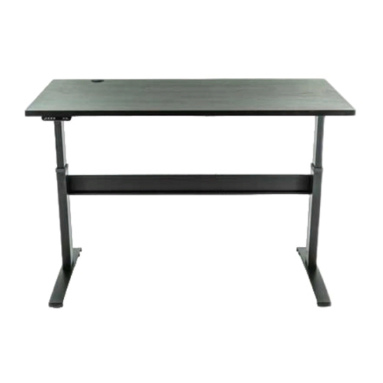
- Page 1 VertDesk Assembly Video: btod.com/v3-assembly 2-Leg Workstation Instruction Instruction #53912 • Dated: 10/17/2018 1 of 12...
- Page 2 Product and its height adjustment mechanism to avoid risk of physical injury or electric shock. KEEP CHILDREN AWAY FROM THE PRODUCT, ITS CONTROL UNITS, AND KEYPADS. BTOD.com • 866.733.0698 • Email: info@btod.com 2 of 12...
-
Page 3: Tools Required For Assembly
W. Right Leg x1 X. J-Channel x1 Note location Left leg has nuts of drive for motor mount. input hole. Legs must be in their lowest position before installation. Left Leg Right Leg BTOD.com • 866.733.0698 • Email: info@btod.com 3 of 12... - Page 4 • Turn hex rod counter clockwise 1/6 of a turn with adjustable wrench, if it is not aligned properly with drive input. • Slide hex rod into leg and align pre-drilled holes in worksurface. BTOD.com • 866.733.0698 • Email: info@btod.com 4 of 12...
- Page 5 • Install u-channel. • Hole placement may vary, depending on width of table. Tip: For proper alignment of pre-drilled holes, start screws but do not fully tighten until all are installed. BTOD.com • 866.733.0698 • Email: info@btod.com 5 of 12...
- Page 6 Step 5 • Slide cross support over leg cross support brackets. Step 6 • Install bolts and do not fully tighten. BTOD.com • 866.733.0698 • Email: info@btod.com 6 of 12...
- Page 7 • Fully tighten bolts in cross support. Tighten bolts Step 9 Optional: Programmable Switch Switch Note: if you have a programmable switch (shown), please refer to the installation instructions included with the switch. BTOD.com • 866.733.0698 • Email: info@btod.com 7 of 12...
- Page 8 Control box can be relocated but the orientation of the box must remain the same. Long side of control box must align with long side of the worksurface. BTOD.com • 866.733.0698 • Email: info@btod.com 8 of 12...
-
Page 9: Cable Routing Diagram
For faultless operation, ensure all cables, electronics, and accessories are cable managed and secured. Excessive load or weight must be distributed evenly. Failure to follow these guidelines may cause intermittent functionality. BTOD.com • 866.733.0698 • Email: info@btod.com 9 of 12... -
Page 10: Standard Switch
- To delete the lower container stop press You will hear a musical tone. Troubleshooting: If you are having any problems with the operation, contact Beyond the Office Door at 866.733.0698 or info@btod.com. BTOD.com • 866.733.0698 • Email: info@btod.com 10 of 12... - Page 11 • Clear all obstructions from the travel path of the desk. • Plug the unit back in the wall. • Press and hold the down arrow key until the table reaches its lowest position. See Packaged Instructions for Programmable Options BTOD.com • 866.733.0698 • Email: info@btod.com 11 of 12...
- Page 12 Step 2: Attach the track to the worksurface using four wood screws. Do not over-tighten the wood screws. Use a low torque setting on the power driver. Step 3: Complete the installation using the instructions that came with the product you are installing. BTOD.com • 866.733.0698 • Email: info@btod.com 12 of 12...
Need help?
Do you have a question about the VERTDESK V3 and is the answer not in the manual?
Questions and answers