Advertisement
Quick Links
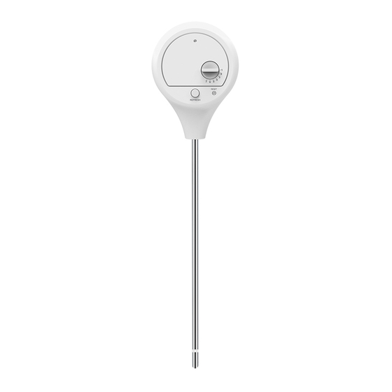
WIRELESS SOIL MOISTURE & TEMPERATURE SENSOR
Model: C3102C
Thank you for selecting this delicate soil sensor. Utmost care has gone into the design
and manufacture of the sensor. Please read the instructions carefully according to the
version you purchased and keep the manual well for future reference.
OVERVIEW
1
3
4
2
1.
LED indicator
- Blinks once during transmission.
2.
[ REFRESH ] key
3.
[ CHANNEL ] rotatory selection switch
- Assign the sensor to Channel 1,2,3,4,5,6 or 7.
4.
[ RESET ] key
5.
Battery compartment
- Accommodates 2 x CR2032 button cells.
6.
Battery door screw
7.
Sensor metal probes
8.
Moisture sensor
GETTING STARTED
1.
Select the sensor channel by using
[CHANNEL ] rotatory selection
switch.
For example: Channel 1 is selected.
2.
Drive the battery door screw counter
clockwise to open the battery door.
3.
Insert 2 x CR2032 button cells into
the battery compartment. Make
sure you insert them the right way
according to the polarity information
marked on the battery compartment.
User Manual
4.
Cover the battery door and drive the
door screw clockwise to close the
battery door.
Note:
Ensure the water tight O-ring is properly
aligned in place to ensure water resistant.
Note:
- Once the channel is assigned to a Wireless sensor, you can only change it by
removing the batteries or resetting the unit.
- After replacing the batteries of the wireless sensor or the unit fails to receive wireless
sensor signal of a specified channel, press [ SENSOR ] key on the console unit to
manually receive the sensor signal again.
WIRELESS SENSOR SIGNAL RECEIVING (DISPLAY CONSOLE)
5
This soil sensor can support different 7CH console, user can base on the following step
to setup the display console.
6
1.
In normal mode, press the [ SENSOR ] key of the console once to start receiving the
sensor signal of current on displaying channel. The signal icon will flash.
For example, when CH 1 is displayed, pressing [ SENSOR ] key will start receive for
CH 1 only.
2.
The signal icon will flash until the reception succeeded. If no signal is received within
5 minutes the icon will disappear.
The icon blinks once every time
when incoming wireless sensor
signal is received (every 60s)
Fair wireless sensor signal
7
3.
If the signal for Ch 1~7 has discontinued and does not recover within 15 minutes,
the temperature and humidity will display "Er" for the corresponding channel.
4.
If the signal does not recover within 48 hours, the "Er" display will become
permanent. You need to replace the batteries of the "Er" channel's sensors and then
press [ SENSOR ] key to pair up with the sensors per each "Er" channel again.
8
Note:
The operation or signal icons of different display consoles may be different, please refer
to the user manual of your display console for more detail.
TEMPERATURE DISPLAY
On the display of the console which the soil sensor is linked to, temperature reading will
be displayed.
SOIL MOISTURE DISPLAY
Soil moisture can be clarified into 5 different levels: Very Dry, Dry , Moist, Wet and Very
Wet.
To determine the moisture of soil, the sensor calibrate the moisture into 16 points, and
correlate them into percentage value:
Points
1
2
3
4
5
6
7
8
9
10
11
12
x 2
13
14
15
16
Note:
The measurement accuracy of the sensor can be affected by the soil condition. For
example, the loose soil may get lower moisture level that compare with the dense soil.
Weak wireless sensor
signal
Bad / no wireless
sensor signal
Percentage
Level
0%
7%
13%
Very Dry
20%
27%
33%
40%
47%
53%
60%
67%
Moist
73%
80%
87%
93%
Very Wet
99%
Dry
Wet
Advertisement

Summary of Contents for CCL ELECTRONICS LTD C3102C
- Page 1 Cover the battery door and drive the door screw clockwise to close the battery door. WIRELESS SOIL MOISTURE & TEMPERATURE SENSOR Model: C3102C Note: User Manual Ensure the water tight O-ring is properly aligned in place to ensure water resistant.
- Page 2 SENSOR PLACEMENT FCC STATEMENT Select the suitable installation site that insert the sensor probes into the soil around This device complies with Part 15 of the FCC Rules. Operation is subject to the following 100mm (4 inch) and sensor should place within 30 meters of the display console to get two conditions: (1) this device may not cause harmful interference, and (2) this device the best transmission performance.
Need help?
Do you have a question about the C3102C and is the answer not in the manual?
Questions and answers