Table of Contents
Advertisement
Quick Links
Advertisement
Chapters
Table of Contents

Summary of Contents for Blastrac 2-45D
- Page 1 Operating Instructions 2-45D MAN-2-45D-EN (Freightliner)
- Page 2 Technical Data Safety Instructions General Transport Initial Operation Operation Maintenance Electrical & Hydraulic Systems Fault Diagnosis Spare parts Design and speci cati ons are subject to change w ithout notice - November 2008...
- Page 4 2-45D Operating Instructions Technical data Contents Chapter 1 1.1 Rating 1.2 Unit specifications 1.3 Operative range and correct usage 1.4 Machine type designation 1.5 Advice for operators of blast cleaning machines...
-
Page 5: Unit Specifications
Required hydraulic flow: min. 200 l/min at 250 bar Required cooling capacity: min. 22,5 kW Required oil tank: min. 350 liters Required drain lines for blast wheel motors: min. 1/2" ..Please contact Blastrac to get more details about other (hydraulic) requirements for the 2-45D machine. -
Page 6: Operative Range And Correct Usage
Recommended filter unit : 2-45 TDC 1.3 Operative range and correct usage The 2-45D is exclusively designed to clean dry, frost- free horizontal surfaces. The machine may not be used for other purposes. The manufacturer will not be liable for damage resulting from such incorrect... -
Page 7: Machine Type Designation
Operating Instructions 2-45D Technical data 1.4 Machine type designation 2 - 45 D number of blastwheels blast cleaning width product code 1.5 Advise for operators of blast cleaning machines accordance with accident prevention regulations for blast cleaning work (VBG 48) the... -
Page 8: Table Of Contents
2-45D Operating Instructions Safety instructions Contents Chapter 2 2.0 Warnings and symbols 2.1 Organisational measures 2.2 Personnel selection and qualification 2.3 Safety precautions applicable to different operating conditions 2.4 Special work within the scope of use of the equipment and maintenance activities as well as repairs during operation 2.5 Definition of the Safety off position... -
Page 9: Warnings And Symbols
Operating Instructions 2-45D Safety instructions 2.0 Warnings and symbols The following denominations and symbols are used in the Operating Instructions to highlight areas of particular importance: Symbol of operational safety. In these Operating Instructions this symbol will be shown next to all safety precautions that are to be taken in order to ensure prevention to life and injury. -
Page 10: Organisational Measures
2-45D Operating Instructions Safety instructions Warning against dangerous voltages. Indications relating to protective devices in electrical appliances. Indications where consultation with manufacturer is required. Instructions relating to periodical checks. Reference to important instructions contained in the Operating Instructions. 2.1 Organisational measures... - Page 11 Operating Instructions 2-45D Safety instructions The Operating Instructions must be supplemented by instructions including the duty to supervise and report relating to particular working practices, for example work organisation, work procedures and personnel allocation. Personnel entrusted with working with the machine must have read the Operating Instructions before starting work, in particular the Safety Instructions chapter.
-
Page 12: Personnel Selection And Qualification
2-45D Operating Instructions Safety instructions To perform maintenance work correctly it is imperative to be equipped with the proper tools for the task in question. The location and the operation of fire extinguishers must be made known on each building site! Take note of the facilities for reporting and fighting fires! 2.2 Personnel selection and qualification... - Page 13 Operating Instructions 2-45D Safety instructions 2.3 Safety precautions applicable to different operating conditions Ban any method of working that impairs safety! Only operate the machine when all safety devices and related safety equipment, e.g. detachable safety devices, emergency stops and suction devices are present and operational!
-
Page 14: Special Work Within The Scope Of Use Of The Equipment And
2-45D Operating Instructions Safety instructions 2.4 Special work within the scope of use of the equipment and maintenance activities as well as repairs during operation Mechanical servicing work: Put the machine in the Safety off position as described in chapter 2.5 for any servicing work on the machine in order to prevent the... -
Page 15: Definition Of The Safety Off Position
Operating Instructions 2-45D Safety instructions 2.5 Definition of the Safety off position Definition: The machine is in a safe condition when it cannot generate any hazard. Putting the equipment in the Safety off position means: Close the shot valves. -
Page 16: Particular Dangerous Aspects Of The Equipment
2-45D Operating Instructions Safety instructions 2.6 Particular dangerous aspects of the equipment Any machine, if it is not used according the regulations, may be hazardous for operating, setting-up and service personnel. The operating authority is responsible for compliance with the... -
Page 17: Hydraulic And Electrical Engineering Regulations
Operating Instructions 2-45D Safety instructions 2.7 Hydraulic and electrical engineering regulations Work on hydraulic equipment or operating materials may only be undertaken by a skilled hydraulic engineer or by trained persons under the guidance and supervision of a skilled hydraulic engineer as well as in accordance with the hydraulic engineering regulations. - Page 18 2-45D Operating Instructions General Contents Chapter 3 Introduction Operating instructions Hydraulic connections Care and maintenance Scope of supply Description Blast wheel Separator, magnetic drum and hopper Abrasive sealing 3.10 Air suction and filter system 3.11 Abrasive media...
-
Page 19: Introduction
Blastrac offers a course on the use of the machine in order to make the operating and maintenance personnel familiar with all elements of... -
Page 20: Hydraulic Connections
Required oil tank: min. 350 liters Required drain lines for blast wheel motors: min. 1/2" ..Please contact Blastrac to get more details about other (hydraulic) requirements for the 2-45D machine. 3.4 Care and maintenance Special attendance and regular maintenance of the machine and its parts are imperative for functioning and safety. -
Page 21: Scope Of Supply
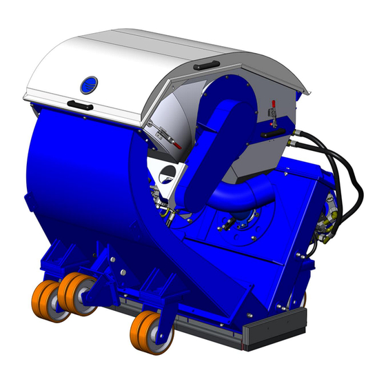
Operating Instructions 2-45D General 3.5 Scope of supply Scope of supply of the machine: Blast cleaning machine (2-45D) Dust hose Operating instructions (2 x) Machine adapter Tow behind magnet sweeper (2-45TBS) 3.6 Description Fig. 3.1 Separator incl. - Page 22 2-45D Operating Instructions General The Blastrac blast cleaning machine 2-45D is a downward blasting machine with a closed abrasive circuit designed for the pre-treatment of horizontal surfaces. The bouncing impact of metallic abrasive onto the surface to be treated thoroughly removes surface contaminants, coats of paint, sealants and thin coatings.
- Page 23 Operating Instructions 2-45D General 3.7 Blast wheel The heart of the blast cleaning machine are two blast wheels that throw the abrasive onto the surface to be cleaned by using centrifugal force. The blast wheels are placed in a protective housing lined with replaceable wear parts.
-
Page 24: Separator, Magnetic Drum And Hopper
2-45D Operating Instructions General 3.8 Separator, magnetic drum and hopper The abrasive separator is mounted to the end of the recovery duct. It separates the abrasive from contaminants and feeds the cleaned abrasive onto the magnetic drum. This magnetic drum functions as a second separator for bigger particles and feeds the cleaned abrasive back to the abrasive storage hopper. -
Page 25: Abrasive Sealing
Operating Instructions 2-45D General 3.9 Abrasive sealing Magnetic seals are fitted to the front and the sides of the blast housing outlet and are surrounded by rubber and brush seals. At the rear there are four seals sliding over the floor. - Page 26 2-45D Operating Instructions General Side brush housing: The inner- and outer side brush are able to float over the treated surface. The brushes are clamped between two guides. This assembly is pressed on the floor by two springs inside the brush housing.
-
Page 27: Air Suction And Filter System
Operating Instructions 2-45D General 3.10 Air suction and filter system The sucked-in air streaming through the complete system when the blast cleaning machine and the filter unit are in operation has the following functions: Cooling of the blast wheels ... - Page 28 2-45D Operating Instructions General The air streams through the machine as follows: Abrasive Air & Dust Fig. 3.7 Air is sucked in at the rear seal and carries along abrasive and dust. The air stream flows through the rebound plenum and carries along abrasive and dust.
-
Page 29: Abrasive Media
Blastrac abrasive. The Blastrac abrasive is of very high quality and owns the rebouncing ability required for the efficient use of model 2-45D. The selection of the abrasive is very important since this is the material to carry out the surface treatment. - Page 30 The effectiveness of the 2-45D depends on the rebound effect which ensures that the abrasive can be re-used. Please take into account that the use of incorrect abrasive increases wear. Our service engineers have the experience to select the appropriate abrasive for the individual cases of application.
- Page 31 2-45D Operating Instructions Transport Contents Chapter 4 4.1 General notes 4.2 Transport 4.3 Operation conditions 4.4 Operation 4.5 Unit specifications...
- Page 32 Chapter 1 "Technical data“. Fig. 4.1 Because of trafic safety, a truck mounted 2-45D must be stored inside the truck before it is transported. Local and general safety precautions and accident prevention guidelines are to be followed.
- Page 33 2-45D Operating Instructions Transport 4.3 Operation conditions Check the surface to be treated for loose parts (stones, screws, etc.). The surface must be swept if necessary. Make sure that the machine can travel over all inequalities on the surface. Small inequalities like weld seams or floor joints are no barriers for the machine.
- Page 34 2-45D Operating Instructions Initial operation Contents Chapter 5 5.1 Preparations for initial operation 5.2 Initial operation...
- Page 35 Operating Instructions 2-45D Initial operation 5.1 Preparations for initial operation Before switching on make sure that all existing protective housings are mounted and that the filter unit is connected correctly. All persons in the proximity of the machine must wear ear protectors, safety glasses with lateral protection as well as safety shoes.
- Page 36 2-45D Operating Instructions Initial operation Check the tightness of the hose connections and the condition of the hose(s) to the filter. Make sure the dust container of the filter unit is empty. Check the separator parts for wear and defects. Remove foreign bodies and dust deposits in order to prevent the separator from being blocked.
- Page 37 Operating Instructions 2-45D Initial operation Fill approx. 150 kg of the selected abrasive (see Chapter 3.11) into the abrasive storage hopper of the blast cleaning machine. The shot valves must be closed whilst doing this. Fig. 5.1 Check that the filter dust collector is operational ready.
- Page 38 Find out the cause of the disturbance and, if necessary, contact your Blastrac customer service engineer. Start driving in the working direction and set the travel speed. Working direction Fig.
- Page 39 Operating Instructions 2-45D Initial operation An indication exceeding the full load value means overloading of the hydraulic system, whereas an indication below the full load value shows that there is not enough abrasive fed to the blast wheel. If necessary re-adjust the abrasive shot valves or refill the...
- Page 40 2-45D Operating Instructions Operation Contents Chapter 6 6.1 Operation 6.2 Hydraulic system 6.3 Switching-off the machine 6.4 What to do if a fault occurs 6.5 Safety shutdown 6.6 Restarting after a fault...
- Page 41 2-45D Operation 6.1 Operation Normal start-up and operation of the blast machine 2-45D is no different from the procedure described in Chapter 5 “Initial operation”. Carry out blasting in parallel tracks. The selection of the correct advancing speed of the blast machine is important for a good blast result.
- Page 42 2-45D Operating Instructions Operation 6.4 What to do if a fault occurs Irrespective of the following information, the local safety regulations are valid in any case for the operation of the machine. First put the machine to its Safety off position. After that start looking for the defect.
- Page 43 Operating Instructions 2-45D Operation...
- Page 44 2-45D Operating Instructions Maintenance Contents Chapter 7 7.1 Recommendations 7.2 Maintenance and inspection list 7.3 Repairing 7.4 The blast pattern 7.5 Setting the blast pattern 7.6 Setting the control cages 7.7 Wear parts 7.8 Changing the liners 7.9 Blast wheel blades & Impeller replacement...
- Page 45 Operating Instructions 2-45D Maintenance 7.1 Recommendations With maintenance and inspection works, please observe Chapter 2 "Safety instructions". Failures due to inadequate or incorrect maintenance may generate very high repair costs and long standstill periods of the machine. Regular maintenance is therefore imperative.
- Page 46 2-45D Operating Instructions Maintenance 7.2 Maintenance and inspection list Check period Check Comments After repairing Check the functionality of all safety devices. Check all accessible screw connections for tight seat. Check whether all machine parts are assembled safely and correctly.
- Page 47 Operating Instructions 2-45D Maintenance Check period Check Comments Daily and prior Check the level of abrasive in Fill the separator equally with the to starting work the storage hopper. selected abrasive up to the bottom of the separator tray. The magnetic valve must be closed whilst doing this.
- Page 48 2-45D Operating Instructions Maintenance Check period Check Comments Weekly Check the rear brushes and Replace if necessary. seals of the machine for wear. Every 3 month Check the condition and Adjust or replace if necessary. tension of the V belts.
- Page 49 As already mentioned in Chapter 5 “Initial operation” we recommend to execute the first repair works on the machine with the help of Blastrac personnel. With this your maintenance personnel gets the opportunity to be trained intensely. Only those repair works are described which occur within the context of maintenance or which are required to replace wear parts.
- Page 50 Correct adjustment of the control cage and thus of the blast pattern is the most important factor for optimum working with the 2-45D blast cleaning machine. Incorrect adjustment of the control cage results in very high wear and...
- Page 51 Operating Instructions 2-45D Maintenance Every time the control cage is replaced, the thread of the blast wheel fastening screw should be checked. Make sure that this screw will be tightened correctly. In addition, absolute care must be taken to clean the thread from dust and abrasive.
- Page 52 2-45D Operating Instructions Maintenance The following 4 factors affect the blast pattern: Turning direction of the blast wheels: The turning direction of the blast wheels must correspond to the instructions on the housing (arrows indicating the turning direction). Worn blast wheel parts: ...
- Page 53 Operating Instructions 2-45D Maintenance 7.6 Setting the control cages The adjustment is effected by loosening the cage clamps and turning the control cage in the suitable direction. The cast grooves on the control cage show the position of the control cage opening. The following adjustment standard value is valid: the control cage opening is approximately opposite to the throwing angle.
- Page 54 2-45D Operating Instructions Maintenance Move the blast head of the blast machine onto a 5-8 mm thick steel plate and blast for 45 seconds at full power without moving the machine from the spot. Stop the abrasive flow and move the machine forward until the blasted area is accessible.
- Page 55 Operating Instructions 2-45D Maintenance 7.7 Wear parts The blast wheel parts Fig. 7.3 Control cage Impeller Blades (set of 6) Blast wheel...
- Page 56 2-45D Operating Instructions Maintenance The liners Fig. 7.4 Top liner outer Top liner inner Side liner Rebound side liner LH Rebound top liner Rebound bottom liner Rebound side liner RH...
- Page 57 Operating Instructions 2-45D Maintenance 7.8 Changing the liners Unscrew the top liner cover and remove the top liner cover and the rubber seal. Fig. 7.5 Remove the bolt in the centre of the blast housing holding the top inner liners (1).
- Page 58 2-45D Operating Instructions Maintenance 7.9 Blast wheel blades & Impeller replacement Fig. 7.6 Remove the top liners (1) as described on the previous pages. Make sure the power unit is stopped, disengage the hydraulics and switch off the PTO.
- Page 59 2-45D Operating Instructions Electrical & hydraulic systems Contents Chapter 8 8.1 Circuit diagram 8.2 Hydraulic diagram...
- Page 60 Operating Instructions 2-45D Electrical & hydraulic systems 8.1 Circuit diagram Please contact Blastrac for a complete manual containing the circuit diagram of the electrical system. Contact Blastrac to get more details about the electrical requirements for the 2-45D machine.
- Page 61 2-45D Operating Instructions Electrical & hydraulic systems 8.2 Hydraulic diagram Please contact Blastrac for a complete manual containing the hydraulic diagram of the hydraulic system. Contact Blastrac to get more details about the hydraulic requirements for the 2-45D machine.
- Page 62 2-45D Operating Instructions Fault diagnosis Contents Chapter 9 9.1 Fault diagnosis - blast machine 9.2 Fault diagnosis - hydraulic and electrical system...
- Page 63 Operating Instructions 2-45D Fault diagnosis 9.1 Fault diagnosis - blast machine Prior to any repair works on the machine or its drives the machine must be secured against unintentional switching-on. Put the machine to its Safety off position. Fault diagnosis...
- Page 64 Contact Blastrac. Recommended Poor abrasive quality. for most applications Blastrac Shot 550 and Shot 460. Worn blast wheel, impeller Replace blast wheel, impeller or or control cage. control cage.
- Page 65 Adjust the blast pattern. Every surface to be treated is different and has its own blast cleaning characteristics. Blastrac is always available to help you choosing the right settings. 9.2 Fault diagnosis - hydraulic and electrical system Prior to any repair works on the machine or its drives the machine must be secured against unintentional switching-on.
- Page 66 2-45D Operating Instructions Spare parts Contents Chapter 10 10.1 Blast wheel unit 10.2 Blast wheel drive 10.3 Blast housing and liners 10.4 Base seals 10.5 Shot valve 10.6 Separator 10.7 Separator seals 10.8 Rebound plenum and swivel castors...
- Page 67 Operating Instructions 2-45D Spare parts 10.1 Blast wheel unit Fig. 10.1 Item Part no. Description QTY. 493966B Cage clamp 500-1010 Control cage RB100A/24 Control cage adjuster RB100A/191 Front plate BE0199 Impeller bolt M12x40 BE0042 Impeller washer M12 600-1015 Impeller 500-1005...
- Page 68 RB165/1 HTD Belt RB165/3 Taper lock bush RB165/2 HTD pulley E02433 Blast motor fill up plate E02178 Wheel motor protection plate RB165 Hydraulic motor E01907 Bearing unit 2-45D E02434 Belt guard bottom plate RB165/4 HTD pulley RB165/5 Taper lock bush...
- Page 69 Item Part no. Description QTY. RB100A/1 Blast housing cover RB100A5/3 Top outer liner RB100A5/2 Top inner liner E02430 Blast housing 2-45D RB100A/25 Liner fixing block E02343 Airflow adjuster RB100A5/4 Side liner RB100A5/5L Rebound side liner LH RB100A5/6 Rebound top liner...
- Page 70 2-45D Operating Instructions Spare parts 10.4 Base seals Fig. 10.4 Item Part no. Description QTY. E10297 Brush housing RB117 Side magnet RB118A Front magnet E10310 Front brush E02198 Rear brush E10278 Side brush outer E10279 Side brush inner E02081 Side seal rubber...
- Page 71 Operating Instructions 2-45D Spare parts 10.5 Shot valve Fig. 10.5 Item Part no. Description QTY. E02120 Cylinder mount bracket E01839RH Magnetic valve RH E01839LH Magnetic valve LH RB100A/19 Clamping ring RB100A/20 Feed spout seal RB100A/10 Feed spout E02121 Valve lever...
- Page 72 2-45D Operating Instructions Spare parts 10.6 Separator Fig. 10.6 Item Part no. Description QTY. RB100A31B27 Separator cover 1.2502.014-50 Drum magnet RB100A4B Deflector RB100A3/31 Hydraulic motor RB100A31B Separator RB100A3/32 Belt pulley RB100A3/34 Drum pulley 222-2301-V Taper lock bush RB100A3/350 Taper lock bush...
- Page 73 Operating Instructions 2-45D Spare parts 10.7 Separator seals Fig. 10.7 Item Part no. Description QTY. E10309 Rubber air guide RB100A34/9 Deflector seal RB100A3/340 Top seal strip RB100A3/330 Top seal edge E10292 Side seal magnetic drum RB100A3/370 Slide seal RB100A3/380 Flow adjuster...
- Page 74 2-45D Operating Instructions Spare parts 10.8 Rebound plenum and swivel castors Fig. 10.8 E02197 Steering handle Ironware Spring cotter 4 mm E02196 Steering bracket E02202 Locking pin Ironware M8x16 bolt - DIN 933 E02201 Steering bracket ring E02181 Transport castor bracket...
- Page 75 Service Manual Side shift & adapter 2-45D MAN-SA2-45D-EN...
- Page 76 Technical Data Safety Instructions General Transport Initial Operation Operation Maintenance Hydraulic System Fault Diagnosis Spare parts Design and speci cati ons are subject to change w ithout notice - November 2008...
- Page 77 Side shift & adapter 2-45D Service Manual Technical data Contents Chapter 1 1.1 Rating 1.2 Unit specifications 1.3 Operative range and correct usage 1.4 Advice for operators...
- Page 78 Side shift & adapter 2-45D Length 1050 mm Width 2350 mm Height 2000 mm Weight 1000 kg Angular movement: Fig. 1.1 The hydraulic cylinder of the machine adapter can swivel the Blastrac 2-45D blast cleaning machine 8° up and 8° down.
- Page 79 1.3 Operative range and correct usage The side shift and machine adapter are exclusively designed to mount a Blastrac 2-45D blast cleaning machine on a truck. The side shift and machine adapter may not be used for other purposes. The manufacturer will not be liable for damage resulting from such incorrect usage.
- Page 80 Side shift & adapter 2-45D Service Manual Safety instructions Contents Chapter 2 2.0 Warnings and symbols 2.1 Organisational measures 2.2 Personnel selection and qualification 2.3 Safety precautions applicable to different operating conditions 2.4 Special work within the scope of use of the equipment and maintenance activities as well as repairs during operation 2.5 Definition of the Safety off position...
- Page 81 Service Manual Side shift & adapter 2-45D Safety instructions 2.0 Warnings and symbols The following denominations and symbols are used in the Operating Instructions to highlight areas of particular importance: Symbol of operational safety. In this Service Manual this symbol will be shown next to all safety precautions that are to be taken in order to ensure prevention to life and injury.
- Page 82 Side shift & adapter 2-45D Service Manual Safety instructions 2.1 Organisational measures The Service Manual is to be kept near the location where the side shift and machine adapter is located and must be within reach at all times! In addition to the Service Manual general and legal regulations...
- Page 83 Service Manual Side shift & adapter 2-45D Safety instructions Spare parts must comply with the technical requirements specified by the manufacturer. This is always guaranteed if original spare parts are used. Intervals for recurring checks and inspections specified in this...
- Page 84 Side shift & adapter 2-45D Service Manual Safety instructions Check the side shift and machine adapter visually for any damage and defects at least once a day! In the event of operational malfunctions the work must be stopped immediately and the side shift and machine adapter secured, and...
- Page 85 Service Manual Side shift & adapter 2-45D Safety instructions If safety devices need to be dismantled during setting up, servicing and repairs, these safety devices must be reinstalled and inspected immediately after completion of the servicing and repair work. Make sure that process materials and replaced parts are...
- Page 86 Side shift & adapter 2-45D Service Manual Safety instructions 2.6 Particular dangerous aspects of the equipment Any equipment, if it is not used according the regulations, may be hazardous for operating, setting-up and service personnel. The operating authority is responsible for compliance with the...
- Page 87 Service Manual Side shift & adapter 2-45D Safety instructions 2.7 Hydraulic engineering regulations Work on hydraulic equipment or operating materials may only be undertaken by a skilled hydraulic engineer or by trained persons under the guidance and supervision of a skilled hydraulic engineer as well as in accordance with the hydraulic engineering regulations.
- Page 88 Side shift & adapter 2-45D Service Manual General Contents Chapter 3 Introduction Operating instructions Hydraulic connections Care and maintenance Scope of supply Description...
- Page 89 Side shift & adapter 2-45D General 3.1 Introduction Blastrac wants to thank you for your decision to employ the side shift and machine adapter for the 2-45D blast cleaning machine. The side shift and machine adapter is designed to mount a Blastrac 2-45D blast cleaning machine on a truck.
- Page 90 Swivel cylinder max. 250 bar Lift cylinder max. 210 bar Please contact Blastrac to get more details about requirements for the 2-45D side shift and machine adapter. 3.4 Care and maintenance Special attendance and regular maintenance of the side shift and machine adapter and its parts are imperative for functioning and safety.
- Page 91 Side shift & adapter 2-45D General 3.5 Scope of supply Scope of supply of the side shift and machine adapter: Machine adapter for 2-45D blast cleaning machine Side shift for 2-45D blast cleaning machine Lift unit for 2-45D blast cleaning machine Adapter frame Service manual (2 x) 3.6 Description...
- Page 92 Side shift & adapter 2-45D Service Manual General Fig. 3.2 Machine adapter complete Lift cylinder bolt Side shift unit complete M24 nut + SLW + PW Split pin Lift unit complete Plain washer Adapter frame Hydraulic cylinder 10 M24x80 bolt + PW...
- Page 93 Service Manual Side shift & adapter 2-45D General The Blastrac side shift and machine adapter is designed to mount a 2-45D blast cleaning machine on a truck. Fig. 3.3 Because the side shift and machine adapter is only designed for the...
- Page 94 Side shift & adapter 2-45D Service Manual Transport Contents Chapter 4 4.1 General notes 4.2 Transport 4.3 Operation 4.4 Unit specifications...
- Page 95 Blastrac. 4.2 Transport When transporting the 2-45D blast machine proceed in such a manner that damage due to the effects of the use of force or incorrect loading and unloading is avoided.
- Page 96 See chapter 7.2 for a detailed description of the periodical checks! Because of traffic safety, a truck mounted 2-45D must be stored inside the truck before it is transported. Local and general safety precautions and accident prevention guidelines are to be followed.
- Page 97 Side shift & adapter 2-45D Service Manual Initial operation Contents Chapter 5 5.1 Preparations for initial operation 5.2 Initial operation...
- Page 98 Service Manual Side shift & adapter 2-45D Initial operation 5.1 Preparations for initial operation All persons in the proximity of the side shift and machine adapter must wear safety shoes. The operator is obliged to wear close- fitting protective clothing.
- Page 99 Side shift & adapter 2-45D Service Manual Initial operation Start driving in the working direction and set the travel speed. Fig. 5.1 Alter the travel direction only after a full standstill.
- Page 100 Side shift & adapter 2-45D Service Manual Operation Contents Chapter 6 6.1 Operation 6.2 Hydraulic system 6.3 What to do if a fault occurs 6.4 Safety shutdown 6.5 Restarting after a fault 6.6 Measures before and after long standstills...
- Page 101 Service Manual Side shift & adapter 2-45D Operation 6.1 Operation Normal operation of the 2-45D side shift and machine adapter is no different from the procedure described in Chapter 5 “Initial operation”. Carry out blasting in parallel tracks. 6.2 Hydraulic system Please look in the hydraulic system manual for a complete description of all controls and settings.
- Page 102 Side shift & adapter 2-45D Service Manual Operation 6.5 Restarting after a fault See Chapter 5 “Initial operation“. All persons in the proximity of the side shift and machine adapter must wear safety shoes. The operator is obliged to wear close-fitting protective clothing.
- Page 103 Side shift & adapter 2-45D Service Manual Maintenance Contents Chapter 7 7.1 Recommendations 7.2 Maintenance and inspection list 7.3 Repairing 7.4 Replacement parts...
- Page 104 Service Manual Side shift & adapter 2-45D Maintenance 7.1 Recommendations With maintenance and inspection works, please observe Chapter 2 "Safety instructions". Failures due to inadequate or incorrect maintenance may generate very high repair costs and long standstill periods. Regular maintenance is therefore imperative.
- Page 105 Side shift & adapter 2-45D Service Manual Maintenance 7.2 Maintenance and inspection list Check period Check Comments After repairing Check the efficiency of all safety devices. Check all screw connections for tight seat. Check whether all side shift and machine adapter parts are assembled safely and correctly.
- Page 106 As already mentioned in Chapter 5 “Initial operation” we recommend to execute the first repair works on the machine with the help of Blastrac personnel. With this your maintenance personnel gets the opportunity to be trained intensely. Only those repair works are described which occur within the context of maintenance or which are required to replace wear parts.
- Page 107 Side shift & adapter 2-45D Service Manual Maintenance 7.4 Replacement parts The following parts must be replaced every one or two years, or every 150 or 300 hours (whatever comes first). Fig. 7.1 Every year or every 150 hours: 1.1 M16 x 35 + SLW + PW (8x) Spring lock washer (2x) 1.2 Split pin (2x)
- Page 108 Service Manual Side shift & adapter 2-45D Maintenance The following parts must be replaced every one or two years, or every 150 or 300 hours (whatever comes first). Fig. 7.2 Every year or every 150 hours: 1.1 M24x80 + PW (2x)
- Page 109 Side shift & adapter 2-45D Service Manual Hydraulic system Contents Chapter 8 8.1 Hydraulic diagram...
- Page 110 Side shift & adapter 2-45D Hydraulic system 8.1 Hydraulic diagram Please look at the hydraulic manual for a complete description, and containing the hydraulic diagram of the hydraulic system. Contact Blastrac to get more details about the hydraulic requirements for the 2-45D machine adapter.
- Page 111 Side shift & adapter 2-45D Service Manual Fault diagnosis Contents Chapter 9 9.1 Fault diagnosis - side shift and machine adapter 9.2 Fault diagnosis - hydraulic system...
- Page 112 Service Manual Side shift & adapter 2-45D Fault diagnosis 9.1 Fault diagnosis - side shift and machine adapter Prior to any repair works on the side shift and machine adapter the equipment must be secured against unintentional switching-on. Put the side shift and machine adapter to its Safety off position.
- Page 113 Side shift & adapter 2-45D Service Manual Spare parts Contents Chapter 10 10.1 Side shift and adapter 10.2 Machine adapter 10.3 Side shift unit 10.4 Lift unit 10.5 Adapter maintenance kits...
- Page 114 Service Manual Side shift & adapter 2-45D Spare parts 10.1 Side shift and adapter Fig. 10.1 Item Part no. / Norm Description QTY. E02301 Machine adapter complete E02323 Side shift unit complete ISO 1234 - 5 x 63 Split pin...
- Page 115 Side shift & adapter 2-45D Service Manual Spare parts 10.2 Machine adapter Fig. 10.2 Item Part no. / Norm Description QTY. RB104A3R Swivel bracket RH ISO 4018 - M16 x 35 Hexagon head bolt + SLW + PW RB317 Bearing bush...
- Page 116 Service Manual Side shift & adapter 2-45D Spare parts Item Part no. / Norm Description QTY. RB104A13 Cylinder washer DIN 127 - A 8 Spring lock washer ISO 4018 - M8 x 25 Hexagon head bolt RB104A2 Adapter plate arm...
- Page 117 Side shift & adapter 2-45D Service Manual Spare parts 10.3 Side shift unit Fig. 10.3 Item Part no. / Norm Description QTY. DIN 933 - M10 x 35 Hexagon head screw + SLW + PW E02152 Mount bracket RH E02151...
- Page 118 Service Manual Side shift & adapter 2-45D Spare parts 10.4 Lift unit Fig. 10.4 Item Part no. / Norm Description QTY. E02325 Lift unit E02159 Manifold mount plate E02282 Manifold roof...
- Page 119 Side shift & adapter 2-45D Service Manual Spare parts 10.5 Adapter maintenance kits The following parts must be replaced every one or two years, or every 150 or 300 hours (whatever comes first). Fig. 10.5 E02424 Adapter maintenance kit 7 (Every year or every 150 hours) 1.1 M16 x 35 + SLW + PW (8x)
- Page 120 Service Manual Side shift & adapter 2-45D Spare parts The following parts must be replaced every one or two years, or every 150 or 300 hours (whatever comes first). Fig. 10.6 E02423 Adapter maintenance kit 6 (Every year or every 150 hours) 1.1 M24x80 + PW (2x)
- Page 121 Operating Instructions 2-45TDC MAN-2-45TDC-EN (Freightliner)
- Page 122 Technical Data Safety Instructions General Transport Initial Operation Operation Maintenance Electrical & Hydraulic Systems Fault Diagnosis Spare parts Design and speci cati ons are subject to change w ithout notice - July 2008...
- Page 123 2-45TDC Operating Instructions Technical data Contents Chapter 1 1.1 Rating 1.2 Unit specifications 1.3 Operative range and correct usage 1.4 Hydraulic power pack (PTO) 1.5 Machine type designation...
- Page 124 Operating Instructions 2-45TDC Technical data 1.1 Rating Unit / designation: Blastrac truck dust collector Machine type 2-45TDC Manufacturer Blastrac BV Utrechthaven 12 NL-3433PN Nieuwegein THE NETHERLANDS 1.2 Unit specifications Dust collector dimensions: Dust collector Dust collector (incl. frame) (excl. frame)
- Page 125 Required hydraulic flow: min. 200 l/min at 250 bar Required cooling capacity: min. 22,5 kW Required oil tank: min. 350 liters ..Please contact Blastrac to get more details about other (hydraulic) requirements for the 2-45TDC machine. Technical data: Rated speed blower fan...
- Page 126 In these cases the user assumes all risks The dust collector 2-45TDC is exclusively designed to be used with the blast cleaning machines 2-45D and 2-45DE. Make sure that the blast cleaning machine and the dust collector will be separately connected to the hydraulic power pack (PTO), consequently the turning directions of all drives must be verified.
- Page 127 PTO, this power pack or PTO must be designed and operated in accordance with the directives of Blastrac, in order to ensure that all devices are functioning and to eliminate possible damage to hydraulic components.
- Page 128 2-45TDC Operating Instructions Safety instructions Contents Chapter 2 2.1 Warnings and symbols 2.2 Organisational measures 2.3 Personnel selection and qualification 2.4 Safety precautions applicable to all operating conditions 2.5 Special work within the scope of use of the equipment and maintenance activities as well as repairs during operation 2.6 Precautions applicable...
- Page 129 Operating Instructions 2-45TDC Safety instructions 2.1 Warnings and symbols The following denominations and symbols are used in the Operating Instructions to highlight areas of particular importance: Symbol of operational safety. In these Operating Instructions this symbol will be shown next to all safety precautions that are to be taken in order to ensure prevention to life and injury.
- Page 130 2-45TDC Operating Instructions Safety instructions Warning against dangerous voltages. Indications relating to protective devices in electrical appliances. Indications where consultation with manufacturer of the dust collector is required. Instructions relating to periodical checks. Reference to important instructions contained in the Operating Instructions.
- Page 131 Operating Instructions 2-45TDC Safety instructions The Operating Instructions must be supplemented by instructions including the duty to supervise and report relating to particular working practices, for example work organisation, work procedures and personnel allocation. Personnel entrusted with working with the dust collector must have read the Operating Instructions before starting work, in particular the Safety Instructions chapter.
- Page 132 2-45TDC Operating Instructions Safety instructions To perform maintenance work correctly it is imperative to be equipped with the proper tools for the task in question. The location and the operation of fire extinguishers must be made known on each building site! Take note of the facilities for reporting and fighting fires! 2.3 Personnel selection and qualification Fundamental duties :...
- Page 133 Do not switch off or remove the exhaust and ventilation devices when the machine is running! Do not work with the Blastrac dust collector when it rains or on moist surfaces! Do not expose the filter cartridges to moisture! All persons in the proximity of the machine must wear ear protectors, safety glasses with lateral protection as well as safety shoes.
- Page 134 2-45TDC Operating Instructions Safety instructions 2.5 Special work within the scope of use of the equipment and maintenance activities as well as repairs during operation Mechanical servicing work: Before starting any mechanical servicing work, put the machine in the Safety off position as described in chapter 2.8 in order to prevent the machine from being switched on accidentally.
- Page 135 Operating Instructions 2-45TDC Safety instructions Secure the maintenance area, if necessary! If the dust collector is switched off in order to do maintenance , repair or adjustment it has to be secured against unintended restart. Always dispose the contents of the dust collector before the end of the working day.
- Page 136 2-45TDC Operating Instructions Safety instructions 2.6 Precautions applicable to some particular dangerous categories Gasses, Dust, Steam, Smoke Do not weld, flame cut or perform grinding works on the dust collector without expressed authorization. Danger of fire or explosion exists! Only work when the dust collector has been switched off and is in the safety off position.
- Page 137 Operating Instructions 2-45TDC Safety instructions 2.8 Safety off position Definition: The dust collector is in a safe condition when it cannot generate any hazard. Putting the equipment in the Safety off position means: Put the blast cleaning machine in the safety off position according to its operating instructions.
- Page 138 2-45TDC Operating Instructions Safety instructions 2.9 Particular dangerous aspects of the equipment Any machine, if it is not used according the regulations, may be hazardous for operating, setting-up and service personnel. The operating authority is responsible for compliance with the safety regulations during operation and maintenance of safety devices supplied with the dust collector as well as the provision of appropriate additional safety devices!
- Page 139 Operating Instructions 2-45TDC Safety instructions 2.10 Hydraulic and electrical engineering regulations Work on hydraulic equipment or operating materials may only be undertaken by a skilled hydraulic engineer or by trained persons under the guidance and supervision of a skilled hydraulic engineer as well as in accordance with the hydraulic engineering regulations.
- Page 140 2-45TDC Operating Instructions Safety instructions Be sure that the operators and maintenance personnel are familiar with the following: Lubrication, cleaning and repair works can only be done when the dust collector is in standstill. Make sure that the dust collector can not be set working during the duration of the works.
- Page 141 2-45TDC Operating Instructions General Contents Chapter 3 3.1 Operating instructions 3.2 Hydraulic connections 3.3 Care and maintenance 3.4 Scope of supply 3.5 Description 3.6 Control panel 3.7 Air suction system...
- Page 142 Blastrac BV offers a course on the use of the dust collector in order to make the operating and maintenance personnel familiar with all elements of the dust collector.
- Page 143 Required oil tank: min. 350 liters (In combination with 2-45D blast head.) ..Please contact Blastrac to get more details about other (hydraulic) requirements for the 2-45TDC machine. 3.3 Care and maintenance Special attendance and regular maintenance of the machine and its parts are imperative for functioning and safety.
- Page 144 Operating Instructions 2-45TDC General 3.5 Description Fig. 3.1 Compressor 6 Pressure tank with valves Blower / Connection to filter unit 7 Cartridge filter chamber Silencer / Air outlet 8 Dust hopper Connection to blast machine 9 Rotating valve Connection to blower 10 Big bag adapter / Dust outlet...
- Page 145 2-45TDC Operating Instructions General 3.6 Control panel Please contact Blastrac for a complete manual containing the description of the control panel. 3.7 Air suction system The air streaming through the complete system during the application of the blast cleaning machine and the dust collector, has the following...
- Page 146 Operating Instructions 2-45TDC General The air streams through the dust collector as follows: Dust & debris Clean air Fig. 3.2 From the blast cleaning machine contaminated air is sucked in at the air inlet of the dust collector and carries along dust and debris. The air stream now enters the filter chamber of the dust collector where the air is sucked through the filters.
- Page 147 2-45TDC Operating Instructions Transport Contents Chapter 4 4.1 General notes 4.2 Transport 4.3 Operation 4.4 Unit specifications...
- Page 148 2-45TDC Transport 4.1 General notes Before the dust collector is used for the first time, Blastrac authorised dealers offer a course to familiarise maintenance and operating personnel with all elements of the dust collector. We are not liable for damage caused by incorrect use of the dust collector by personnel not trained by Blastrac.
- Page 149 2-45TDC Operating Instructions Initial operation Contents Chapter 5 5.1 Preparations for initial operation 5.2 Initial operation...
- Page 150 Operating Instructions 2-45TDC Initial operation 5.1 Preparations for initial operation Before switching on make sure that all existing protective housings are mounted and that the dust collector is connected correctly. All persons in the proximity of the machine must wear ear protectors, safety glasses with lateral protection as well as safety shoes.
- Page 151 The operator is obliged to wear close-fitting protective clothing. Please contact Blastrac for a complete manual containing the description of the control panel. The dust hoppers of the dust collector must be emptied after each use! Switch on the rotating valves to empty the dust hoppers in the big bags.
- Page 152 2-45TDC Operating Instructions Operation Contents Chapter 6 6.1 Operation 6.2 Hydraulic system 6.3 Emptying the dust hoppers 6.4 Switching-off the machine 6.5 Troubleshooting 6.6 Safety shutdown 6.7 Restarting after a fault 6.8 Measures before and after long standstills...
- Page 153 (can) run over the electric cables, hydraulic hoses and dust hoses. 6.2 Hydraulic system Please contact Blastrac for a complete manual describing all controls and settings. 6.3 Emptying the dust hoppers The level of the dust hoppers must always be checked. Make sure...
- Page 154 Operating Instructions Operation 6.4 Switching-off the machine Please contact Blastrac for a complete manual describing all controls and settings. Make sure that all turning dust collector and blower parts have come to standstill and that all hydraulic power devices have been shut down complete before any inspection or maintenance works are started.
- Page 155 Operating Instructions 2-45TDC Operation 6.8 Measures before and after long standstills Standstill of the machine for a maximum of 3 months. Before a long standstill period Make sure that the dust hoppers of the dust collector are empty. Protect the electric and hydraulic components from moisture, heat, dust and shocks.
- Page 156 2-45TDC Operating Instructions Maintenance Contents Chapter 7 7.1 Recommendations 7.2 Maintenance and inspection list 7.3 Repairing 7.4 Belts 7.5 Fitting the belts 7.6 Tensioning the belts 7.7 Taper locks 7.8 Replacing the filter cartridges 7.9 Air pulse system 7.10 Water separator 7.11 Compressor 7.12 Timer unit...
- Page 157 Operating Instructions 2-45TDC Maintenance 7.1 Recommendations With maintenance and inspection works, please observe Chapter 2 "Safety instructions". Failures due to inadequate or incorrect maintenance may generate very high repair costs and long standstill periods of the dust collector. Regular maintenance therefore is imperative. Operational safety and service life of the dust collector depend, among other things, on proper maintenance.
- Page 158 2-45TDC Operating Instructions Maintenance 7.2 Maintenance and inspection list Check period Check Comments After repairing Check the efficiency of all safety devices. Check all accessible screw connections for tight seat. Check whether all machine parts are assembled safely and correctly. Daily and prior Check the hose connections to starting work...
- Page 159 Operating Instructions 2-45TDC Maintenance Weekly Check the belt tension of the Allow 5 to 7 mm at approx. 10kg HTD drives. both ways. Check the belt tension of the V Allow 5 to 7 mm at approx. 10kg belts. both ways. Fill up the bearing units of the Depending on the use of the machine with grease.
- Page 160 As already mentioned in Chapter 5 “Initial operation” we recommend to execute the first repair works on the dust collector having support of Blastrac personnel. With this your maintenance personnel gets the opportunity to be trained intensely. Only those repair works are described which occur within the context of maintenance or which are required to replace wear parts.
- Page 161 Operating Instructions 2-45TDC Maintenance 7.4 Belts The belt drive is designed for the required drive power. Forcing the drive to grant a higher output by overtensioning the belt results in belt breaks, bearing damage and thus to lower efficiency. A low belt tension results in slippage causing an increased belt temperature and thus to premature destruction of the belts.
- Page 162 2-45TDC Operating Instructions Maintenance 7.6 Tensioning the belts The correct belt pre-tension is of great importance for the perfect output transmission and for maintaining the normal service life of the belts. Insufficient or excessive pre-tensioning frequently leads to premature failure of the belts. Over-tensioning often causes bearing defects in motors and bearing units.
- Page 163 Operating Instructions 2-45TDC Maintenance Fig. 7.2 Fig. 7.3 Fig. 7.4 Demounting Demount the screws (fig. 7.2) in the belt pulleys. Lubricate the thread and the tip of the screw and turn it into the bore (fig. 7.3). Turn the screw until the taper lock is loosely seated inside the pulley and, thus, the assembly is loose on the shaft (fig.
- Page 164 2-45TDC Operating Instructions Maintenance 7.8 Replacing the filter cartridges Open the bottom maintenance doors (1) of the filter unit in order to get access to the filter cartridges. Alternatively there is the possibility to swing down the dust hoppers (2). This has to be done very carefully! Swing down the dust hoppers only when the driving motors are in standstill and the main switch of the machine is secured.
- Page 165 Unscrew the wing nut by hand. Make sure that both the wing nut and the rod seal washer end up in your hands (or pockets)! Spares are available at Blastrac. Remove the old filter cartridge and replace it with a new one.
- Page 166 2-45TDC Operating Instructions Maintenance 7.9 Air pulse system The dust collector is provided with an air pulse cleaning system which increases the life of the filter cartridges. This system works by use of pressurized air, built up by a belt driven compressor. The air is led through a water separator to the pulse system.
- Page 167 In that case replace the defective parts or have it checked by Blastrac. When there is pressure but the pulse system does not function, there might be a problem in the electronic system which controls the pulsing system.
- Page 168 The timer unit controls the air pulse system. This unit is at delivery of the dust collector already programmed with regard to optimal filter cleaning. If however doubts arise about settings, this unit can be checked. We advice to contact Blastrac support in order to prevent operational problems.
- Page 169 2-45TDC Operating Instructions Electrical & hydraulic systems Contents Chapter 8 8.1 Circuit diagram 8.2 Hydraulic diagram...
- Page 170 Operating Instructions 2-45TDC Electrical & hydraulic systems 8.1 Circuit diagram Please contact Blastrac for a complete manual containing the circuit diagram of the electrical system. Contact Blastrac to get more details about the electrical requirements for the 2-45TDC machine.
- Page 171 2-45TDC Operating Instructions Electrical & hydraulic systems 8.2 Hydraulic diagram Please contact Blastrac for a complete manual containing the hydraulic diagram of the hydraulic system. Contact Blastrac to get more details about the hydraulic requirements for the 2-45TDC machine.
- Page 172 2-45TDC Operating Instructions Fault diagnosis Contents Chapter 9 9.1 Fault diagnosis - dust collector 9.2 Fault diagnosis - hydraulic and electrical system...
- Page 173 Operating Instructions 2-45TDC Fault diagnosis 9.1 Fault diagnosis - dust collector Prior to any repair works on the equipment or its drives the equipment must be secured against unintentional switching- on. Put the machine to its Safety off position. Fault Possible cause Remedy Unusual noises To little clearance or wrong...
- Page 174 Prior to any repair works on the equipment or its drives the equipment must be secured against unintentional switching- on. Put the machine to its Safety off position.. Please contact Blastrac for a complete manual describing the fault diagnosis of the hydraulic and electrical system.
- Page 175 2-45TDC Operating Instructions Spare parts Contents Chapter 10 10.1 Compressor unit 10.2 Filter top section 10.3 Filter cartridge 10.4 Air pulse system 10.5 Filter bottom section 10.6 Blower...
- Page 176 Operating Instructions 2-45TDC Spare parts 10.1 Compressor unit Fig. 10.1 Item Part no. Description QTY. 490693 Compressor 001244 Air filter E00635 Water separator E00636 Bracket for water separator 491825 V-belt 491824 V-pulley E01627 Taper lock E04087 Hydraulic motor E02288 Pre-tank...
- Page 177 2-45TDC Operating Instructions Spare parts 10.2 Filter top section Fig. 10.2 Item Part no. Description QTY. E02344 Hose connector 150 E02118 Suction connector RB20504 Suction hood E01842 Pressure sensor 490691 Control valve 001134 Air valve 2381-365 Filter vacuum gauge RB2055 Pressure tank E01303 Safety valve...
- Page 178 Operating Instructions 2-45TDC Spare parts 10.3 Filter cartridge Fig. 10.3 Item Part no. Description QTY. 001403 Venturi 739205 Cartridge hook 490803-1 Cartridge filter B21163 Rod seal (delivered with filter cartridge) 000123 Wing nut M10...
- Page 179 2-45TDC Operating Instructions Spare parts 10.4 Air pulse system Fig. 10.4 Item Part no. Description QTY. E01036 Manometer B20057 Adaptor knee 10mm x 1/2" mbsp, swivel B21750 Non return valve E00674 Adaptor 10 x 1/4" mbsp E00670 Knee adaptor swivel 6 x 1/8” mbsp E00030 Vent dust excl.
- Page 180 Operating Instructions 2-45TDC Spare parts 10.5 Filter bottom section Fig. 10.5 Item Part no. Description QTY. 500-4005-SU Hydraulic motor E02365 Motor bracket E01877 Coupling hub E01876 Coupling sleeve E02363 Dust hopper RH not shown E02362 Dust hopper LH E01872 Rotating valve (incl. motor bracket) E01811 Vibrator motor E02370...
- Page 181 2-45TDC Operating Instructions Spare parts 10.6 Blower Fig. 10.6 Item Part no. Description QTY. RB266 Silencer RB2703 Blower throttle 970385 Handle E01846 Bearing unit complete RB270A/9 Vibration damper RB267 Silencer adapter E02069 Belt cover RB270A/11 Taper lock B20429/1 HTD Pulley B20428 HTD Belt RB273...
- Page 182 13201 North Santa Fe Avenue Oklahoma City, OK 73114 Ph: 800-256-3440 F: 405-478-8608 blastrac.com Product Warranty Standard Equipment Products: Blastrac warrants its Blastrac Standard Equipment Products against defects in quality of material and workmanship, under normal and proper use for a period of 1 Year from the date of delivery, as noted on the returned warranty registration card, or, in the case of Rental Fleet Machines, 180 Days from the date of assignment to Rental Fleet.
- Page 183 Blastrac Returned Merchandise Authorization (RMA) Form. Blastrac will then send the RMA form to the customer authorizing the return of the parts for warranty evaluation. The parts must be received within sixty (60) days following the RMA origination date or the warranty claim will be denied.
- Page 184 ® the information recorded here by registering online at blastrac.com, or complete this page and fax to 866-485-1046, or if you prefer, detach and mail to: Blastrac, 13201 North Santa Fe Avenue, Oklahoma City, OK 73114-9901...
- Page 185 Contact Blastrac Canada 5125 Timberlea Blvd. Mississauga, Ontario, Canada L4W 2S3 Tel: 1-866-669-6643 Fax: 866-669-6644 www.blastrac.ca...
Need help?
Do you have a question about the 2-45D and is the answer not in the manual?
Questions and answers