Table of Contents
Advertisement
Quick Links
Quick Guide
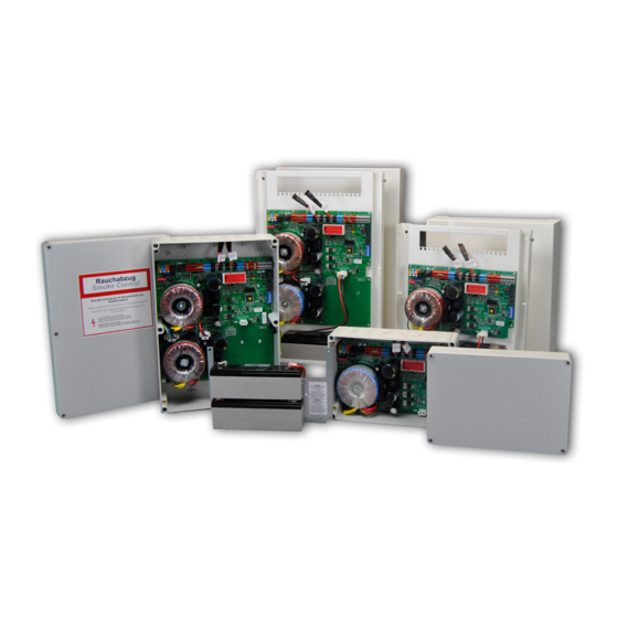
SHEV-3 / -6 (-AP)
Valid for following part numbers:
ST4 3140 (SHEV-3)
ST4 3141 (SHEV-6)
ST4 3146 (SHEV-3-AP)
ST4 3151 (SHEV-6-AP)
Only valid in combination with the attached sheet
KA_SHEV-3-6(-AP)_EN_10
Issue: 1.0 / 08.2018
KA
SHEV-3 / -6 (-AP)
„Safety instructions and warranty conditions"!
www.simon-protec.com
info@simon-protec.com
EN
1.0
For further information, please visit
our product website:
short.simon-protec.com/sheven
Date: 30.08.2018
Advertisement
Table of Contents

Summary of Contents for SIMON PROtec SHEV-3
- Page 1 Quick Guide SHEV-3 / -6 (-AP) SHEV-3 / -6 (-AP) Valid for following part numbers: ST4 3140 (SHEV-3) ST4 3141 (SHEV-6) ST4 3146 (SHEV-3-AP) ST4 3151 (SHEV-6-AP) For further information, please visit our product website: short.simon-protec.com/sheven Only valid in combination with the attached sheet „Safety instructions and warranty conditions“!
-
Page 2: Table Of Contents
Table of contents 1. General ............................3 1.1 Foreword to this quick guide ....................3 1.2 Use for the intended purpose ....................3 2. Functional description ......................3 2.1 Power supply (Tested according to EN 12101-10) ............... 3 2.2 Emergency power supply ..................... 3 2.3 Control electronics (Tested according to prEN 12101-9) ............ -
Page 3: General
General 1. General 2. Functional description 1.1 Foreword to this quick guide SHEV 3 / 6 (Smoke and Heat Exhaust Ventilation) represent the compact control panel system, main- This quick guide serves as a fast introduction for ly used in staircases for smoke extraction and daily the installation by trained, experienced specialist ventilation. -
Page 4: Functions
Functions 3. Functions 3.1 Ventilation function In order to use the SHEV 3 / 6 for ventilation, venti- Many different action behaviors can be allocated to lation OPEN / CLOSE switches can be connected. the switches. Therefore see table 1 underneath. Pressing both switches (OPEN / CLOSE) simulta- neously causes the function STOP. -
Page 5: Gap Ventilation
Mounting 4. Mounting 3.2 Gap ventilation Gap ventilation can be activated by setting DIP- switch SW1 – 3 to ON. This function is time con- Danger trolled and factory-set to 3 seconds. Mounting shall be carried out only by pro- ATTENTION fessional personnel (qualified electrician)! The dead man function in the OPEN direction is in-... -
Page 6: Mounting Steel-Sheet Housing
Mounting Figure 3: Mounting points plastic housing Figure 5: Mounting points steel-sheet housing SHEV 6 SHEV 6-AP 4.2 Mounting steel-sheet housing Figure 4: Mounting points steel-sheet housing SHEV 3-AP Figure 6: Connecting cable Mounting points housing Cable tie Battery port Page 6... -
Page 7: Electrical Connection
Mounting 4.3 Electrical connection DANGER Disconnect the power supply cord for all poles from the mains. The connection of the SHEV 3 / 6 (-AP) must be done volt-free! Figure 7: Wiring diagram total (simplified illustration) Page 7... -
Page 8: Fas Auto-Reset Function
Mounting Figure 9: Wiring diagram thermostat INFORMATION The use of shielded cables is recommended for the detection lines. Figure 8: Wiring diagram smoke detector 4.4 FAS Auto-RESET function 4.5 Wire lengths Generally, all SHEV-alarms must be reseted man- INFORMATION ually by pressing the RESET button (onboard / EOS). -
Page 9: Commissioning
Commissioning 5. Commissioning Figure 11: Mounting-points battery ATTENTION SHEV 6 plastic housing Only after the SHEV 3 / 6 (-AP) has been commis- sioned successfully and the permanent on-site mains power supply is ensured, the battery may be installed and connected. INFORMATION An error message if the battery is disconnected may appear at least after 8 minutes (green LED flashes,... -
Page 10: Troubleshooting
Commissioning 5.3 Troubleshooting ATTENTION ATTENTION After connecting the battery pack, the RESET but- ton must be pressed for 5 seconds to initialize the Due to the low loop current, the insulation resistance SHEV! of the monitored wires (B1, B2 and B3) must be checked! The insulation resistance must be >... -
Page 11: Technical Data
Technical data 6. Technical data Power supply Information Nominal voltage 230 V AC Acceptable voltage range 195 V AC to 264 V AC 0.56 A (SHEV 3) Power consumption 1.20 A (SHEV 6) C 16 A Min. series fuse (on site) Connected load 103 VA (SHEV 3) 206 VA (SHEV 6) - Page 12 Technical data Connection data of the emergency switches (HE 080 / HE 082 / HE 087 & HE 081 / HE 086) Maximum number of main emergency switches (e.g. HE 080 / HE 082 / HE 087) Maximum number of the off site emergency switches (e.g.
- Page 13 Technical data Connection and operation Connection see chapter Figure 7: „Wiring diagram total (simplified illustra- tion)“ on page 7 Terminal clamps Tension spring clamps 0.5 mm² – 2.5 mm² Deadlock according to prEN 12101-9 Option, factory setting: Yes Maximum wire length between control unit and see chapter 4.5 „Wire lengths“...
-
Page 14: Appendix
7. Appendix 7.4 Company addresses 7.1 Manufacturer‘s declaration 7.4.1. System manufacturer We hereby declare the conformity of SIMON PROtec Systems GmbH the product with the applicable guide- Medienstraße 8 lines. The declaration of conformity 94036 Passau can be viewed in the company and will be delivered Tel.: +49 (0) 851 988 70 - 0...
Need help?
Do you have a question about the SHEV-3 and is the answer not in the manual?
Questions and answers