Advertisement
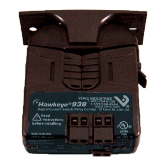
H938
Wiring ExamplE
CONTACTOR
Motor
Z201497-0D
PAGE 1
Alta Labs, Enercept, Enspector, Hawkeye, Trustat, Veris, and the Veris 'V' logo are trademarks or registered trademarks of Veris Industries, L.L.C. in the USA and/or other countries.
CURRENT MONITORING
CONTROLLER
DO
(Relay
Coil)
DI
(Status)
CONTROL
POWER
Fan or Pump
©2009 Veris Industries USA 800.354.8556 or +1(0)503.598.4564 / support@veris.com
INSTALLATION GUIDE
Split-Core Current Switch, Adjustable Output,
with Command Relay
Installer's Specifications
Sensor Power
Insulation Class
Frequency Range
Temperature Range
Humidity Range
Hysteresis
Terminal Block Maximum Wire Size
Terminal Block Torque (nominal)
Agency Approvals
Do not use the LED status indicators as evidence of applied voltage.
quick install
1.
Disconnect and lock out power to the conductor to be monitored.
2.
Plan the installation:
Locate a mounting surface for the removable mounting bracket that will allow
the monitored conductor to pass through the iris, or "window" when it is installed
and keep the product at least 1/2" (13mm) from any uninsulated conductors (CE).
Determine cable routing for the controller connection, allowing wiring to reach
the mounting location.
3.
Install mounting bracket
Drill holes to mount the bracket to the chosen surface using the included screws.
4.
Wire the output connections between the sensor and the controller.
5.
Snap thesensor over the wire to be monitored and clip the assembly to the
mounting bracket.
6.
Close up and power up.
DimEnsions
Removable Mounting Bracket
1.1"
(26 mm)
(21 mm)
3.1"
(79 mm)
(70 mm)
Ø = 0.3"
(8 mm)
3.0"
(76 mm)
938
Induced from monitored conductor
-15° to 60°C (5° to 140°F)
10-90% RH, non-condensing
4 in-lbs (0.45 N-m)
UL 508 open device listing
1.0"
(25 mm)
Bracket can be mounted
on either side for added
0.8"
installation flexibility.
Self-gripping
Iris
2.8"
Use DIN Rail
1.4"
Mounting clip
(36 mm)
(Veris part
2.5"
number AH01) to
(64 mm)
mount on stan-
dard DIN rail.
600VAC RMS
50/60Hz
10% Typical
14 AWG
06091
Advertisement
Table of Contents

Related Manuals for VERIS INDUSTRIES, INC. Hawkeye 938


Summary of Contents for VERIS INDUSTRIES, INC. Hawkeye 938
-
Page 1: Quick Install
INSTALLATION GUIDE CURRENT MONITORING H938 Split-Core Current Switch, Adjustable Output, with Command Relay Installer’s Specifications Sensor Power Induced from monitored conductor Insulation Class 600VAC RMS Frequency Range 50/60Hz Temperature Range -15° to 60°C (5° to 140°F) Humidity Range 10-90% RH, non-condensing Hysteresis 10% Typical Terminal Block Maximum Wire Size... -
Page 2: Troubleshooting
INSTALLATION GUIDE H938 opEration calibration Before beginning calibration, establish normal load conditions. The H938 is a current-sensitive switching device with integral command relay that monitors current (amperage) in the conductor passing through it. A change in amperage in the monitored conductor that crosses the switch (setpoint) threshold plus the hysteresis value will cause the resistance of the status output to change state, similar to the action of a mechanical switch.
Need help?
Do you have a question about the Hawkeye 938 and is the answer not in the manual?
Questions and answers