
Summary of Contents for Krendl 500
- Page 1 OWNERS MANUAL MODEL #500 60 YEARS OF AMERICAN INGENUITY KRENDL MACHINE COMPANY • 1201 SPENCERVILLE RD DELPHOS, OHIO 45833 • TELEPHONE 800-459-2069 • FAX 419-695-9301 E - MAIL: krendl@krendlmachine.com • WEB SITE: www.krendlmachine.com...
- Page 2 CONGRATULATIONS ON YOUR PURCHASE OF KRENDL EQUIPMENT MODEL #500 OWNER'S MANUAL FOR ASSURED SAFETY AND CONFIDENCE, PLEASE READ THIS MANUAL CAREFULLY BEFORE INSTALLING AND OPERATING YOUR MACHINE. E-MAIL ADDRESS IS: krendl@krendlmachine.com WEB SITE IS: www.krendlmachine.com...
-
Page 3: Table Of Contents
Table of Contents PAGE INTRODUCTION ....... . GENERAL SAFETY INFORMATION ....DECALS . -
Page 4: Introduction
This manual has been prepared to help you obtain the maximum efficiency and service from your Krendl equipment. The machine is designed to condition and apply fibers with the utmost in dependable performance. -
Page 5: General Safety Information
MODEL #500 GENERAL SAFETY INFORMATION Important: Read all instructions before operating this unit. This equipment can be potentially dangerous and must be used in strict accordance with instructions. Disclaimer Notice: The manufacturer will not be legally responsible for any injury or damage resulting from the improper use of this equipment or the failure to follow instructions. - Page 6 MODEL #500 Safety/Caution • Be Safe - Keep away from moving parts. • Be Safe - Make sure all guards and hopper bar are in proper place before operating machine. Guards and safety devices/switches should not be removed, modified or by-passed. Hands should never pass below hopper bar.
-
Page 7: Decals
MODEL #500 DECALS Rotating parts can be dangerous! You can snag clothes, Keeping the filter clean will result in longer hair, hands, etc. This can cause serious injury or death. blower life and better performances. Made in the U.S.A. Manufacturer information is provided here along with machine model, and serial number. - Page 8 MODEL #500 Operating machine at specified voltage will result Indicates this unit has two power sources that in longer machine life and better performance. should be disconnected before servicing to re- duce the risk of serious injury or death. Specifies the voltage this outlet is rated for.
-
Page 9: Returned Goods Procedure
MODEL #500 RETURNED GOODS PROCEDURE: When returning products to Krendl for repair, first obtain a return goods authorization, and you will be given shipping instructions. The product must be shipped PREPAID: Krendl Machine Company Telephone: 800-459-2069 1201 Spencerville Rd Fax:... -
Page 10: Warranty
MODEL #500 WARRANTY: Krendl Machine Company (Company) warrants to each original purchaser (Buyer) of its machines that such products will be free of manufacturing defects for a period of 2 years from the date of shipment to the Buyer. (This does not include accessories, pumps, blowers, wall scrubbers, etc.) -
Page 11: Assembly
Units shipped to European countries will have standard (2) two prong 230V 16 amp plugs supplied. Units shipped overseas to other than Europe do not have plugs and receptacles on input cords due to the varying electrical plug configurations in different countries, unless provided by Krendl agents or suppliers. -
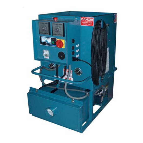
Page 12: Basic Components
MODEL #500 BASIC COMPONENTS This is a view of the basic components of your machine. It shows the location of each item and gives the function of each. Use this as a guide throughout the manual. (illustration C) A) BASE UNIT—Lower frame unit supporting blower box, speed reducer, motor, airlock and hopper. -
Page 13: Theory Of Operation
These units blow the fiber closer to settled density which eliminates the need for overblowing material to compensate for progressive settling. OPERATING INSTRUCTIONS: MODEL #500 Machine Hook-up This unit comes ready for connection to insulation hose, power cords, and accessories. - Page 14 MODEL #500 input cord on unit and not to exceed 50' in length. (See Voltage Drop Chart Below.) Caution: Operating unit with less than required voltage or inadequate generator size will result in damage to electrical components. This machine is marked with the correct input voltage on input cords located on bottom of the Main Control Panel.
- Page 15 MODEL #500 Machine Hook-up (cont.) (illustration E) Electrical Hook-up for 240volt, 60hz. (illustration F) IMPORTANT NOTE FOR 3-WIRE CORD: A separate isolated ground is required that connects the frame of the machine to an earth ground source. Serious injury or death may result if machine is not properly grounded. If you have any further questions, consult a qualified electrician.
-
Page 16: Electrical Operation
MODEL #500 Electrical Operation PRESS KILL SWITCH TO IMMEDIATELY STOP MACHINE AT ANY TIME! 1. Make sure Kill Switch is out by pulling. (See illustration G) 2. Turn red Main Disconnect Switch to ON position. (See illustration G) 3. Set 4-Position Selector Switch to OFF. (See illustration G) 4. -
Page 17: Mechanical Settings
MODEL #500 Mechanical Settings The control end of your machine contains blower and slidegate controls to adjust your machine for each application and type of fiber. (See illustration J) Blower control (air) and slidegate (material feed) are adjusted according to: APPLICATION: Open blow, retro-sidewall and spray-on applications require varying amounts of control. -
Page 18: General Maintenance
MODEL #500 Mechanical Settings (cont.) OPTIONAL SHREDDER ASSEMBLY: If this unit is supplied with a shredder assembly; airlock/agitator speeds are preset at the factory. No further sprocket setting speeds are needed, as this system will accommodate most fibers and applications. However, the shredder direction can be adjusted as described below. - Page 19 MODEL #500 General Maintenance (cont.) ROTOR PLATE REPLACEMENT: 1.To check plates for proper angle, measure distance between outer edge of metal plates. (See illustration N-1) This measurement should be 4 3/4". Measure all six plates and replace as needed. 2.Remove damaged baseplate assembly from shaft using ratchet drive wrench with extension and 1/2" socket.
- Page 20 MODEL #500 General Maintenance (cont.) SPROCKETS: CHECK SPROCKETS FOR WEAR. Misalignment and/or loose sprockets and improper chain tension causes the premature wear of chain and sprockets. All sprockets, except speed reducer and idler sprockets, have been secured with a medium grade Loctite (general purpose thread locker), to prevent gradual movement.
- Page 21 MODEL #500 General Maintenance (cont.) AGITATOR MOTOR: If agitator motor runs hot, activating the manual reset on motor, or if unit does not run properly, refer to troubleshooting sections of manual. The agitator motor should start quickly and run smoothly. If not, shut motor off immediately and check the cause.
- Page 22 MODEL #500 General Maintenance (cont.) CARBON BRUSH REPLACEMENT 8 AMP (4 AMP 230 volt) 2-STAGE BLOWER: (See illustration R) Order replacement brushes from your supplier to assure proper brush style. Carbon brushes need to be replaced when excessive arcing is produced on the commutator.
-
Page 23: Electrical System
MODEL #500 ELECTRICAL SYSTEM General Operation: (See illustration T for sequence and illustrations G,U,V and W for components) This unit is powered by one or two separate input sources connected at the bottom of the Main Panel Box. Turning the Main... - Page 24 MODEL #500 Electrical System (cont.) Electrical Diagram Description for Pages 22-29: Tags have been placed at the end of each wire in the electrical system to identify specific wires. This identification code is as follows: First letter - identifies component classification...
- Page 25 MODEL #500 Rev. Date: 3/14/18 Page 22...
- Page 26 MODEL #500 Rev. Date: 3/14/18 Page 23...
- Page 27 MODEL #500 Rev. Date: 3/14/18 Page 24...
- Page 28 MODEL #500 Rev. Date: 3/14/18 Page 25...
- Page 29 MODEL #500 Rev. Date: 3/14/18 Page 26...
- Page 30 MODEL #500 Rev. Date: 3/14/18 Page 27...
- Page 31 MODEL #500 Rev. Date: 3/14/18 Page 28...
- Page 32 MODEL #500 Rev. Date: 3/14/18 Page 29...
-
Page 33: Troubleshooting
MODEL #500 TROUBLESHOOTING WARRANTY This unit is backed by a warranty for manufacturer's defects. If machine needs service during that time, call your supplier immediately. Do not attempt to service, as this voids warranty. IMPORTANT At any signs of trouble with your machine, stop immediately, disconnect power and call your supplier. - Page 34 MODEL #500 Electrical Troubleshooting IMPORTANT Whenever power is interrupted to unit (i.e., unplugged, main disconnect switch off, kill switch depressed), power must be restored by correcting power interruption condition and pressing green start button. Problem Corrective Action 1) Voltmeter showing no voltage or low voltage.
- Page 35 MODEL #500 Electrical Troubleshooting (cont.) 6) Blower motor does not run in manual mode. (4-Position A. Check wiring connections on Selector Switch contacts. (Located on back of Main Control Panel door.) Selector Switch.) A. Clean or replace Filter on Blower Door.
-
Page 36: Parts List
Certain information is needed concerning your specific machine when ordering replace- ment parts: • Machine Model number (i.e. Model #500) • Serial Number • Date Purchased • Voltage of unit (main input): 120V, 240V or 230V (overseas) - single or double input •... - Page 37 MODEL #500 NON SHREDDER UPPER HOPPER and LOWER BASE UNIT ASSEMBLY Rev. Date: 3/14/18 Page 34...
- Page 38 MODEL #500 NON SHREDDER UPPER HOPPER and LOWER BASE UNIT ASSEMBLY PARTS LIST Item # Part # Description 501-R1 Hopper 501-ASSY Hopper Assembly (includes: hopper, agitators, and bearing assemblies) 502-R2 Guard, Screen KMC-203 Decal, Emergency Stop Switch, Kill, Assembly (includes: Kill Switch and Contact-Decal not included)
- Page 39 MODEL #500 NON SHREDDER UPPER HOPPER and LOWER BASE UNIT ASSEMBLY PARTS LIST Item # Part # Description Key, 1/4" x 1 1/4" Pin, Hinge (2) 22-1 FSB080 Roll Pin, 5/32" x 5/8" (2) 2530-1 Latch, Bent, 5/16-18 x 2" Hex (2)
- Page 40 MODEL #500 SHREDDER UPPER HOPPER and LOWER BASE UNIT ASSEMBLY Rev. Date: 3/14/18 Page 37...
- Page 41 MODEL #500 SHREDDER UPPER HOPPER and LOWER BASE UNIT ASSEMBLY PARTS LIST Item # Part # Description 501-R1 Hopper 501-ASSY Hopper Assembly (includes: hopper, agitators, and bearing assemblies) 509-P Guard, Screen KMC-203 Decal, Emergency Stop Switch, Kill, Assembly (includes: Kill Switch and Contact-Decal not included)
- Page 42 MODEL #500 SHREDDER UPPER HOPPER and LOWER BASE UNIT ASSEMBLY PARTS LIST Item # Part # Description Key, 1/4" x 1 1/4" Pin, Hinge (2) 22-1 FSB080 Roll Pin, 5/32" x 5/8" (2) 2530-1 Latch, Bent, 5/16-18 x 2" Hex (2)
- Page 43 MODEL #500 BLOWER BOX ASSEMBLY Rev. Date: 3/14/18 Page 40...
- Page 44 MODEL #500 BLOWER BOX ASSEMBLY PARTS LIST Item # Part # Description Box, Blower 567-R1 Bracket, Blower (small blower) 30-1 574-R1 Bracket, Blower (large blower) 31-1 409-C Spacer, Blower (2") (small blower) 31-2 409-D Spacer, Blower (2 1/2") (large blower)
- Page 45 MODEL #500 MECHANICAL and ELECTRICAL CONTROL ASSEMBLY/OPTIONS Rev. Date: 3/14/18 Page 42...
- Page 46 47-1 ELU11-109077 Electrical Upgrade (115V, 50 Hz.) (double input, double 12.5 A blowers) 47-2 ELU07-546-M Electrical Upgrade (230V, 50 Hz.) (Special Order Only) (Not Shown) 47-3 543-M RCU, 500 (50HZ - Special Order Only) (Not Shown) RC395-D R.C. Cord Assembly, 150Ft. DPDT Style D 18-3 SJ Wire, #18-3(SJ) x 150 Ft.
- Page 47 MODEL #500 OPTIONAL SHREDDER ASSEMBLY & HOPPER EXTENSION Rev. Date: 3/14/18 Page 44...
- Page 48 MODEL #500 OPTIONAL SHREDDER ASSEMBLY & HOPPER EXTENSION PARTS LIST Optional Shredder Assembly (560-R4) Item # Part # Description 56 560-5-Assy-R2 Shredder Box Assembly 56-1 560-5-A-R2 Shredder Box w/Removable End 56-2 560-6-B-R2 Agitator, Shredder Box, 6-tine, 14" (short) 56-3 560-1-B-R2 Agitator, Shredder Box, 6-tine, 14" (long)
- Page 49 MODEL #500 120 V.A.C. 60 Hz. ELECTRICAL UPGRADE PARTS LIST (2) 2-STAGE BLOWERS (ELU11-109064) Electrical Exploded Parts List Part# Description Item# 543-M-31-R1 Box, Electrical 14” x 14” x 7” 46-1 543-M-31-4 Plate, Backing for Electric Box 46-2 543-M-38 Alarm for Pre-Alarm System, 24V...
- Page 50 MODEL #500 120 V.A.C. 60 Hz. ELECTRICAL UPGRADE PARTS LIST (1) 3-STAGE BLOWERS (ELU11-109066) Electrical Exploded Parts List Part# Description Item# 543-M-31-R1 Box, Electrical 14” x 14” x 7” 46-1-1 543-M-31-4 Plate, Backing for Electric Box 46-1-2 543-M-38 Alarm for Pre-Alarm System, 24V...
- Page 51 MODEL #500 120 V.A.C. 60 Hz. ELECTRICAL UPGRADE PARTS LIST (2) 3-STAGE BLOWERS (ELU11-109067) Electrical Exploded Parts List Item# Part# Description 46-2-1 543-M-31-R1 Box, Electrical 14” x 14” x 7” 46-2-2 543-M-31-4 Plate, Backing for Electric Box 46-2-3 543-M-38 Alarm for Pre-Alarm System, 24V...
- Page 52 MODEL #500 240 V.A.C. 60 Hz. ELECTRICAL UPGRADE PARTS LIST (2) 2-STAGE BLOWERS (ELU11-109063) Electrical Exploded Parts List Item# Part# Description 46-3-1 543-M-31-R1 Box, Electrical 14” x 14” x 7” 46-3-2 543-M-31-4 Plate, Backing for Electric Box 46-3-3 543-M-38 Alarm for Pre-Alarm System, 24V...
- Page 53 MODEL #500 240 V.A.C. 60 Hz. ELECTRICAL UPGRADE PARTS LIST (1) 3-STAGE BLOWERS (ELU10-109065) Electrical Exploded Parts List Item# Part# Description 46-4-1 543-M-31-R1 Box, Electrical 14” x 14” x 7” 46-4-2 543-M-31-4 Plate, Backing for Electric Box 46-4-3 543-M-38 Alarm for Pre-Alarm System, 24V...
- Page 54 MODEL #500 240 V.A.C. 60 Hz. ELECTRICAL UPGRADE PARTS LIST (2) 3-STAGE BLOWERS (ELU10-109070) Electrical Exploded Parts List Item# Part# Description 46-5-1 543-M-31-R1 Box, Electrical 14” x 14” x 7” 46-5-2 543-M-31-4 Plate, Backing for Electric Box 46-5-3 543-M-38 Alarm for Pre-Alarm System, 24V...
- Page 55 MODEL #500 230 V.A.C. 50 Hz. ELECTRICAL UPGRADE PARTS LIST (2) 3-STAGE BLOWERS (ELU10-109072) Electrical Exploded Parts List Item# Part# Description Item# Part# Description 47-1 543-M-31-R2 Box, Electrical 14” x 14” x 7” 47-20 508-2 Switch, Kill 47-2 543-M-31-4 Plate, Backing for Electric Box...
-
Page 56: Parts List
MODEL #500 115 V.A.C. 50 Hz. ELECTRICAL UPGRADE PARTS LIST (2) 3-STAGE BLOWERS (ELU11-109077) Electrical Exploded Parts List Item# Part# Description Item# Part# Description 47-1-1 543-M-31-R2 Box, Electrical 14” x 14” x 7” 47-1-20 508-2 Switch, Kill 47-1-2 543-M-31-4 Plate, Backing for Electric Box... -
Page 57: Glossary
MODEL #500 GLOSSARY BRIDGING Tendency of fiber to cling in the hopper forming an air pocket above the airlock. This hinders the normal feeding process of the machine. (Cubic feet per minute). A measurement of volume or quantity of air flowing at a certain rate, or air moving capability, of a blower. -
Page 58: Service Record
MODEL #500 SERVICE RECORD DATE MAINTENANCE PERFORMED COMPONENTS REQUIRED Rev. Date: 3/14/18 Page 55... - Page 59 60 YEARS OF AMERICAN INGENUITY Made in the U.S.A. KRENDL MACHINE COMPANY • 1201 SPENCERVILLE RD DELPHOS, OHIO 45833 • TELEPHONE 800-459-2069 • FAX 419-695-9301 E - MAIL: krendl@krendlmachine.com • WEB SITE: www.krendlmachine.com...
Need help?
Do you have a question about the 500 and is the answer not in the manual?
Questions and answers