Advertisement
Quick Links
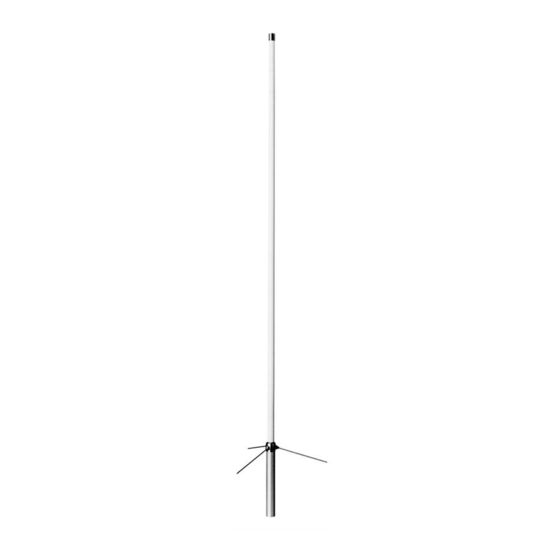
2m/70cm Dual Band High Performance Gain Base Station Antenna
Description
1. High
performance
structures.
2. Direct element joint structure with
two interconnected FRP outer-
shells. Enables the antenna to
maintain the same strength as one
with one piece structure. The ring
gasket makes the antenna water-
proof, and therefore maintains
performance even in rainy weather.
When required, the antenna can be
easily assembled or disassembled
by adjusting the joint bracket
accordingly.
3. Professional quality maximum
wind resistance is achieved by the
rugged structure. Superior water-
proofing
eliminates
VSWR that might otherwise
happen in climatic weather. This
antenna may also be used in seaside
or contaminated air environments
as it is rust and corrosion free.
4. Both of the bands, 2m and 70cm,
can be operated simultaneously by
using optional antenna duplexer.
5. DC ground structure, which
escapes high voltage caused by
lightning, protects your radio and
equipment.
Adjustment
All X-Series antennas are completely
adjustment free. If VSWR of an anten-
na is extraordinarily high, see if each
connecting part is well contacted. It is
most likely due to bad contact in the
coaxial cable and/or connector connec-
tion, or soldering problem. Be sure to
use 50ohm coaxial cable to feed the
antenna.
C-Load
FREQUENCY: 144-148 MHz
GAIN:
POWER:
IMPEDANCE: 50 Ohms
VSWR:
MAX WIND
RESISTANCE: 60m/sec (135 MPH)
MAST DIAMETER
ACCEPTED:
LENGTH:
WEIGHT:
CONNECTOR: UHF Female
WARRANTY: 1 Year against
unstable
DIAMOND ANTENNA Products are distributed by RF PARTS COMPANY
435 S. Pacific Street • San Marcos, CA 92078 • (760) 744-0900
www.diamondantenna.net
X50A
Specifications
435-450 MHz
4.5 dB
7.2 dB
200 Watts
less than 1.5:1
30-62mm
(1-1/5" to 2-2/5")
1.7m (67")
0.9 kg (2.3 lbs.)
defects in material
or workmanship.
VSWR Charts
Assembly
1. Attach three radial elements to the
feedpoint section, which is a one piece
structure with FRP element outer shell.
Radial Element
Feedpoint Section
Lock Nut
Radial Element
2. Fix two mast brackets to support
pipe. Then connect coaxial cable to the
feedpoint section through support
pipe. Fix support pipe to the feedpoint
section with a lock screw by aligning
the holes at the bottom of the section
and top of the pipe.
Lock
Washer
Feedpoint section
Support Pipe
Align the
holes and fix
Fig. B
3. Attach assem-
bled antenna to a
mast
whole balance into
account and fix it
firmly as shown in
Fig. C.
Mast
Fig. C
Fig. A
Mast
Brackets
by
taking
Advertisement

Related Manuals for Diamond X50A


Summary of Contents for Diamond X50A
-
Page 1: Specifications
Be sure to Fig. C. use 50ohm coaxial cable to feed the Mast antenna. Fig. C DIAMOND ANTENNA Products are distributed by RF PARTS COMPANY 435 S. Pacific Street • San Marcos, CA 92078 • (760) 744-0900 www.diamondantenna.net... - Page 2 For Your Safety Antenna Installation Precautions To determine antenna installation location, there are several factors to be taken into account. First thing is anten- Please read the following safety precautions na propagation direction to specific target stations. As to before antenna assembly. whether there are any obstacles such as tall buildings on the line of sight.
Need help?
Do you have a question about the X50A and is the answer not in the manual?
Questions and answers
I have the x50 mounted to a 17ft painted steel pole. Do I need to run a separate ground wire? If so, where would the best attachment be?