Table of Contents
Advertisement
Advertisement
Table of Contents

Summary of Contents for Bavaria Yachts 301
- Page 1 Instruction Manual for Operating Panel 301 and 302 Edition: 12/2006...
- Page 2 Edition: 12/2006...
-
Page 3: Table Of Contents
Rear View of Panel 301 ........ - Page 4 Edition: 12/2006...
-
Page 5: Introduction And Overview
Introduction and Overview Two panels are available for the operation and power supply. Panel 301 is designed for central monitoring and control of all electrical functions on board the yacht. Panel 302 supplies the 230V devices with power when there is a land connection. -
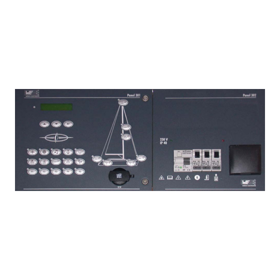
Page 6: Panel 301 Controls
Panel 301 Controls Fig. 2 Overview of panel 301 (1) Display (2) Scroll and acknowledgment buttons (3) Function buttons (4) Socket 12V/20A (5) Lighting buttons The current status of the function and lighting buttons is shown by the respective LED. -
Page 7: Function Buttons
1.1.1 Function Buttons Button Description/Function Compass Switches the compass on and off. The button status is saved when the power supply has been switched off and is kept until the power is switched back on again. Navigation Switches the navigation device on and off. The button status is saved when the power supply has been switched off and is kept until the power is switched back on again. - Page 8 Button Description/Function Waste water Switches the waste water pump on and off. The button status is saved when the power supply has been switched off and is kept until the power is switched back on again. CAUTION: Do not dry run the waste water pump! Panel Switches the background lighting of the panel and display on.
-
Page 9: Lighting Buttons
1.1.2 Lighting Buttons These buttons are used to switch the various lighting sources on and off. The button status is saved when the power supply has been switched off and is kept until the power is switched back on again. Fig. -
Page 10: Menu Structure
Alarms will be shown when triggered. See also section 1.2.2. After activating the main switch, you will see the following start screen on the display: BAVARIA YACHTS With the help of the scroll buttons and the acknowledgment button, you can select and view the various information and menus. -
Page 11: Menu
øøåÆÆÆÆÆÆÆ 12.0V consumer battery . Change the alarm value for the Possible values: consumer battery (BV). 11.5 V to 13.5 V Scroll buttons BAVARIA YACHTS Acknowledgement button Sern Fig. 4 Panel 301 menu Introduction and Overview Edition: 12/2006... -
Page 12: Alarms
To acknowledge the alarm, press the acknowledgment button for 2 seconds. Acknowledgement button freshwater AC BAVARIA YACHTS øøøøøøøøøø 100% Alarm Press for 2 secs. If "Alarm" appears on the display , this means that an alarm has been acknowledged but the cause of the alarm has not yet been fixed . - Page 13 Fig. 6 Overview of panel 302 (1) Installation point for radio (optional) (2) LED (green) for residual current circuit breaker (3) Residual current circuit breaker FI / (4) Observe warning symbols (5) Automatic circuit breaker - kitchen (6) Automatic circuit breaker - shower (16A) (16A) (7) Automatic circuit breaker - boiler (16A) (8) Socket 220V (9) LED (red) for boiler on...
-
Page 14: Warning Symbols On Panel 302
Warning against dangerous voltages. – Potentially lethal voltages are still present at some parts on the rear of panels 301/302 - even when the panels have been switched off at the main switch. Introduction and Overview... -
Page 15: Electrical Connections
– Potentially lethal voltages are therefore still present at some parts on the rear of this panel (in- put B16/FI) - even when the panel has been switched off at the residual current circuit breaker. – Measurement and service work to panels 301/302 may only be performed by specially quali- fied personnel. - Page 16 Fig. 7 Rear view of the panel 301 - terminal assignment (1) Monitoring of fresh water tank 2 (bow) (2) Monitoring of waste tank 2 (3) Monitoring of fresh water tank 1 (AC) (4) Monitoring of waste tank 1 (5) Monitoring of charger...
-
Page 17: Terminal Assignment
2.2.1 Terminal Assignment Connector [1] Monitoring fresh water tank 2 (bow) Cable Fresh water tank 2 4/4, wt Fresh water tank 2 3/4, br Fresh water tank 2 2/4, gr Fresh water tank 2 1/4, ye Fresh water tank 2 COM/GND Connector [2] + [4] Monitoring waste tank... - Page 18 Connector [7] Bow cable (only for Match series) Cable Top light - not used Steam light - not used Sailing light - not used Fresh water pump - not used [8] Stern cable, plus option Connectio Connector cable Cable Description Stern light Function monitoring 10W/2A...
- Page 19 Connectio Connector [12] Socket Cable Description Socket 12V No function monitoring 192W/16A NOT switched [14] Reserved for function Connectio Connector buttons F1-F5 Cable Description Reserve button 1 No function monitoring 60W/5A Button Reserve button 2 No function monitoring 60W/5A Button Reserve button 3 No function monitoring 60W/5A...
- Page 20 Connectio Connector [16] Light cable Cable Description Heating No function monitoring 60W/5A Button Control line for thermostat Radio (optional) Function monitoring 120W/10A Button CB radio (optional) Function monitoring Button [17] Sower suction extractor Connectio Connector pump Cable Description Shower suction extractor pump 13+13a+ No function monitoring 270W/30A...
- Page 21 Fig. 8 Rear view of the panel 301 - micro-fuses (1) Water pump (10A) (2) Cooling unit (30A) (3) Shower pump (30A) (4) Inside lighting cabin 1 (20A) (5) Inside lighting cabin 2 (20A) (6) Navigation (20A) (7) Reserve button (20A)
-
Page 22: Rear View Of Panel 302
Rear View of Panel 302 DANGER Panel 302 is supplied with 230 V~ ± 5 %, 50/60 Hz line voltage. – Observe the safety instructions in section „Safety Instructions“ on page 15. 2.3.1 Terminal Assignment Fig. 9 Rear view of the panel 302 - terminal assignment (1) 1 x Boiler (2) 3 x Shower (3) 3 x Kitchen... -
Page 23: Circuit Diagram
Circuit Diagram Fig. 10 Circuit diagram Electrical Connections Edition: 12/2006... - Page 24 Electrical Connections Edition: 12/2006...
Need help?
Do you have a question about the 301 and is the answer not in the manual?
Questions and answers