
Related Manuals for HUSTLER FasTrak SDX


Summary of Contents for HUSTLER FasTrak SDX
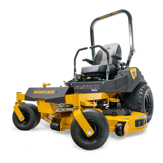
- Page 1 Hustler FasTrak ® ® General Service Manual 200 South Ridge Road Hesston, Kansas 67062 121878 REV C...
- Page 2 WARNING The engine exhaust from this product contains chemicals known to the state of California to cause cancer, birth defects or other reproductive harm. NOTICE OF REQUIREMENT OF SPARK ARRESTER MUFFLER This equipment may create sparks that can start fires around dry vegetation. California Public Resources Code Section 4442.6 provides that it is unlawful to use or operate an internal combustion engine on any forest-covered, brush-covered, or grass-covered land unless the engine is equipped with a spark arrester maintained in effective working order.
-
Page 3: Table Of Contents
General Information ........1-1 ® Hustler Service Program ......1-1 Maintenance Introduction . - Page 4 Deck Belt Installation ........6-4 Belt Routing and Tensioning ......6-5 Side Discharge Deck Belt Routing.
-
Page 5: General Information
Service Program ® in the engine compartment and under the seat platform areas; minute dust particles are abrasive to close-tolerance This manual is part of a service package for the Hustler ® engine and hydraulic assemblies. FasTrak SDX mowers. Use of this manual in conjunction ®... - Page 6 REV C 121878...
-
Page 7: Safety
SAFETY • Do not smoke while refueling. Extinguish all cigarettes, cigars, pipes and other sources of ignition. • Do not remove fuel cap or fill tank with engine running or while engine is hot. Clean up any This safety alert symbol is used to call attention to a gasoline spills. -
Page 8: Operation Precautions
Understand Machine Operation Never leave machine unattended with ignition key in switch, especially with children present. Only qualified and trained personnel should operate Follow daily and weekly checklists, making sure hoses the equipment. are tightly secured and bolts are tightened. ... -
Page 9: Maintenance Precautions
• Hydrogen gas forms inside the battery. This gas them. is both toxic and flammable and may cause an Use original Hustler replacement parts or parts that ® explosion if exposed to flame. Always disconnect are equivalent in overall performance. - Page 10 • Prevent the battery terminals from touching any If you spill acid on yourself: metal mower parts when removing or installing • Flush your skin with water. the battery. • Apply baking soda or lime to help neutralize the • Do not allow metal tools to short between the acid.
-
Page 11: Torque
TORQUE Standard Torques The following chart lists the standard torque values for the threaded fasteners found in this manual. Torque all cap screws, nuts and set screws to these values unless a different torque is shown in the Special Torques section. Size ft-lbs N•m... - Page 12 REV C 121878...
-
Page 13: Power Unit Maintenance
POWER UNIT MAINTENANCE Steering Adjustments Untrained maintenance personnel should never Steering Control Lever Neutral Adjustment attempt to make any adjustments or repairs to the mower’s drive system while the engine is running. The mower’s steering has been factory adjusted to The following procedures should be performed by eliminate creeping when the steering control levers are in the trained maintenance personnel only. - Page 14 • Place the steering control lever in the park brake position. If neutral is set properly, you should not Shown with steering control levers in the park brake position hear the transmission whine. Shown with steering control levers in the neutral position A.
-
Page 15: Park Brake Spring Adjustment
Park Brake Spring Adjustment 10. IMPORTANT: Unbolt the seat platform from the mower frame. Occasionally check the park brake spring adjustment using • Disconnect the two female spade connectors the following method: from each other (from step #3). 1. This procedure does not require engine power, •... -
Page 16: Steering Control Lever Stops
Steering Control Lever Stops This procedure will require that the unit to be raised to allow the drive wheel to rotate. • Block the mower up off of the ground using only appropriate vehicle stands (minimum weight rating of 2000 pound)s. Use in pairs only. -
Page 17: Belts
Use SAE 20W50 motor oil, 15W50 synthetic oil, very short time. or 20W50 synthetic oil when changing the system oil and filter. Hydraulic Pump Belt Adjustment Hustler Full Synthetic 20W50 Hydrostatic Transmission Oil is ® recommended. The transmission drive belt tension remains constant by When the hydraulic system oil is cold, the fluid level should means of a tension idler and spring. - Page 18 • Remove the ignition switch key. standard oil filter wrench is used to change filter. The • Disconnect the negative battery cable. threads are right handed. Use a Hustler approved filter ® 2. Remove the three 1/4” filter guard screws and filter element only.
- Page 19 13. Re-install the expansion tank cap by hand. Be careful 1. Raise the rear of the mower and block with certified not to overtighten. jack stands. The rear wheels need to be able to rotate freely and clear of all obstructions. 14.
- Page 20 7. With the bypass valve closed and the engine running, slowly move the steering control lever in both forward and reverse directions (5 or 6 times). Check the oil level, and add oil as required after stopping the engine. 8. It may be necessary to repeat Steps 6 and 7 until all the air is completely purged from the system.
-
Page 21: Tires
Drive wheels ....8–12 psi (55–83 KPa) Front wheels ....8–12 psi (55–83 KPa) If you wish to use non-pneumatic tires on your Hustler ®... - Page 22 REV C 4-10 121878...
-
Page 23: Engine Maintenance
Check the engine oil daily and after every 4 hours of operation. The mower must be level when checking the oil. A. Oil drain valve Refer to the Engine Owner’s Manual and maintenance schedule for oil recommendation and capacities. Hustler ® Figure 5-1 Motor Oil is recommended. -
Page 24: Engine Air Filter
Engine Air Filter Kawasaki engine Perform engine air filter maintenance per the Maintenance Schedule shown elsewhere in this manual. A specially designed dry filter is standard equipment on these mowers and supplies clean combustion air to the engine. Figure 5-3 & Figure 5-5 Some of these mowers are equipped with a safety filter. - Page 25 Kohler engine shown Kohler engine shown A. Safety filter A. Air cleaner canister C. Clamp Figure 5-6 B. Dust cap Figure 5-8 Kawasaki engine shown Do not clean the element, but replace with a new element only. Cleaning used air filter elements, through improper cleaning procedures, can get dust on the inside of the filter causing dirt ingestion and engine failure.
-
Page 26: Fuel Evaporation System Filter
The fuel hose is connected to the fuel tank as shown. It Fuel Evaporation System Filter connects the fuel tank to the engine’s fuel pump. Figure 5-12 & Figure 5-13 Hustler FasTrak SDX mowers have a fuel evaporation ® ®... - Page 27 Kohler engine shown Kawasaki engine shown A. Fuel tank B. Fuel line A. Fuel tank C. Fuel evaporation B. Vapor lines system filter Figure 5-13 D. Carbon canister The vapor lines are connected to the fuel tank as shown. Figure 5-15 They connect the fuel tank to the engine’s vapor port.
-
Page 28: Engine Rpm Settings
Engine RPM Settings The engine rpm’s are set at the factory for maximum mowing efficiency. Occasionally it may be necessary to check and adjust the settings. The idle speeds should be set as follows: Kawasaki FX691 / FX730 ENGINE SPEEDS MODEL NO. -
Page 29: Deck Adjustments
DECK ADJUSTMENTS Deck Leveling Side Discharge Deck Shown Leveling the deck must be done in the following manner and order: 1. Check tire pressures to make certain they are properly inflated before starting level deck. recommended pressures are as follows: Drive wheels tire pressure . -
Page 30: Blades
Blades Mower Blade Maintenance IMPORTANT: Refer to the Safety section of this manual for blade handling safety information. Refer to the Mower Blade Replacement section for blade removal and installation. Mower blades are sharp and can cut. Wrap the blade(s) or wear gloves and use extra caution when servicing them. - Page 31 Comparison of Warped and Straight Blades A 15/16" wrench is required to remove the 5/8" cap screw holding the blade to the spindle shaft. NOTE: A blade holding tool (P/N 381442) is available from Hustler Turf Equipment. ® It is designed to prevent the blades from rotating when they are being removed or installed on the spindle.
-
Page 32: Belts
When mounting blades, rotate them after installation to 1. Route the belt around all the pulleys except the left ensure blade tips do not touch each other or sides of the deck spindle. mower. 2. Grasp the belt at the two locations shown and pull the belt over the left spindle pulley. -
Page 33: Belt Routing And Tensioning
Belt Routing and Tensioning The following notes are the same for the different decks that are available. 1. There is no tension adjustment of this belt. 2. Route belt as shown. Side Discharge Deck Belt Routing Figure 6-11 121878 REV C... -
Page 34: Rear Discharge Deck Belt Routing
Rear Discharge Deck Belt Routing Figure 6-12 REV C 121878... -
Page 35: Electrical
ELECTRICAL Main Electrical Harness Schematic — Kawasaki 121878 REV C... -
Page 36: Main Electrical Harness Schematic - Kohler
Main Electrical Harness Schematic — Kohler WHT/RED (20) GRN/WHT (20) BLK (20) REV C 121878... -
Page 37: Main Harness To Fuel Gauge Voltage Converter Schematic
Main Harness to Fuel Gauge Voltage Converter Schematic BLK (20) ORG (20) PIN 1 PIN 1 BLK (20) PIN 2 PIN 2 ORG (20) PIN 3 PIN 3 GRN (20) PIN 4 PIN 4 PIN 5 PIN 5 PIN 6 PIN 6 PIN 7 PIN 7... - Page 38 REV C 121878...
-
Page 39: Maintenance
Initial transaxle system oil and filter change must be after the first 75 hours of use or 1 year whichever comes first. Thereafter, replace filter and oil in each transaxle every 2 years or 200 hours, whichever comes first. Hustler ®... -
Page 40: Maintenance Locator Chart
Inspect ROPS after the first 20 hours of operation and then after every 300 hours of operation or yearly whichever comes first. 10. Refer to engine owner’s manual for engine service information. NOTE: * After completing maintenance cycle (300 hours), repeat cycle. Maintenance Locator Chart Kawasaki 1. - Page 41 1. Engine Oil Fill & Dipstick 2. Fuel Filter 3. Engine Air Cleaner 4. Engine Oil Drain Valve 5. Battery 6. Fuel Tank 7. Engine Oil Filter 8. Deck Lift Pivot Zerks (4) 9. Park Brake Switch (2) 10. Drive Tire 11.
- Page 42 1. Engine Oil Fill & Dipstick 2. Fuel Filter 3. Engine Air Cleaner 4. Engine Oil Drain Valve 5. Battery 6. Fuel Tank 7. Engine Oil Filter 8. Deck Lift Pivot Zerks (4) 9. Park Brake Switch (2) 10. Drive Tire 11.
-
Page 43: Troubleshooting
TROUBLESHOOTING SUGGESTED SYMPTOMS PROBABLE CAUSES REMEDIES SUGGESTED SYMPTOMS PROBABLE CAUSES REMEDIES Mower creeps when Steering linkage needs Adjust linkage steering control levers are adjustment Starting motor does not Steering control levers not Place steering control in neutral crank in park brake position or levers in park brake switch not adjusted position or re-adjust switch... - Page 44 REV C 121878...
- Page 45 INDEX PAGE PAGE Avoid Acid Burns .............2-4 Maintenance Schedule .......... 8-1 Avoid Fire Hazards ..........2-2 Mower Blade Maintenance ........6-2 Belts ..............4-5 Mower Blade Removal ........... 6-3 Blades ..............6-2 Operate Machine Safely ........2-2 Carbon Canister ............5-3 Operation Precautions ........... 2-2 Deck Belt Adjustment ..........6-4 Park Brake Spring Adjustment ......
Need help?
Do you have a question about the FasTrak SDX and is the answer not in the manual?
Questions and answers