
Subscribe to Our Youtube Channel
Summary of Contents for Engel CC300
- Page 1 » User Guide « CC300 Operator Panel User Guide (Preliminary Version 0.2) P/N: XXXX-XXXX...
-
Page 3: Table Of Contents
7.1.2................................20 7.1.3. RFID Read/Write Zone ........................20 7.1.4. Emergency Stop Switch ........................21 7.1.5. Buttons for Tilting the CC300 Operator Panel ................... 21 7.1.6. Touch Display ............................. 22 7.1.7. Touch Display Care and Cleaning ....................... 22 7.1.8. Traversing Buttons ..........................23 7.1.9. - Page 4 7.3.1. USB Ports ............................29 7.4. Top and Bottom View ..........................30 7.5. Accessing internal Components ........................ 31 7.5.1. Opening the CC300 Operator Panel ....................31 7.5.2. Closing the CC300 Operator Panel ..................... 34 8. Maintenance and Prevention ......................35 8.1.
-
Page 5: Table Of Figures
Fig. 29: Removong the lithium battery from the battery holder ..............35 Fig. 30: Dimensioned view of the CC300 glass front (print side - reversed image) ........42 Fig. 31: Dimensioned rear and side view of the CC300 operator panel ............43... -
Page 6: Introduction
2. Introduction CC300 Operator Panel – User Guide 2. Introduction Kontron Europe GmbH would like to point out that the information contained in this manual may be subject to technical alteration, particularly as a result of the constant upgrading of Kontron Europe GmbH products. -
Page 7: Symbols Used In This User Guide
2. Introduction CC300 Operator Panel – User Guide 2.1. Symbols used in this User Guide Symbol Meaning This symbol indicates the danger of injury to the user or the risk of damage to the product if the corresponding warning notices are not observed. -
Page 8: Important Instructions
3. Important Instructions CC300 Operator Panel – User Guide 3. Important Instructions This chapter contains instructions which must be observed when using the CC300 Operator Panel. The manufacturer’s instructions provide useful information on your device. 3.1. Note on the Warranty Due to their limited service life, parts which by their nature are subject to a particularly high degree of wear (wearing parts) are excluded from the warranty beyond that provided by law. -
Page 9: General Safety Instructions For It Equipment
Only approved original accessories (optional parts) approved by Kontron Europe GmbH may be used. The DC-input must fulfill SELV requirements of EN60950-1 standard. The chassis of the CC300 Operator Panel must be protective earthed by establishing a large-area contact between the grounding cable and an appropriate grounding connection point. - Page 10 4. General Safety Instructions for IT Equipment CC300 Operator Panel – User Guide It must be assumed that safe operation is no longer possible, • if the device has visible damage or • if the device no longer functions.
-
Page 11: Electrostatic Discharge (Esd)
4. General Safety Instructions for IT Equipment CC300 Operator Panel – User Guide 4.1. Electrostatic Discharge (ESD) A sudden discharge of electrostatic electricity can destroy static-sensitive devices or micro-circuitry. Therefore proper packaging and grounding techniques are necessary precautions to prevent damage. -
Page 12: Instructions For The Lithium Battery
4. General Safety Instructions for IT Equipment CC300 Operator Panel – User Guide 4.2. Instructions for the Lithium Battery The installed mainboard is equipped with a lithium battery. For the replacing of this battery please observe the instructions described in the “Replacing the Lithium Battery”... -
Page 13: Electromagnetic Compatibility
5. Electromagnetic Compatibility CC300 Operator Panel – User Guide 5. Electromagnetic Compatibility 5.1. Electromagnetic Compatibility (EU) This product is intended only for use in industrial areas. The most recent version of the EMC guidelines (EMC Directive 2004/108/EC) and/or the German EMC laws apply. If the user modifies and/or adds to the equipment (e.g. -
Page 14: Nameplate Of The Cc300 Operator Panel
5. Electromagnetic Compatibility CC300 Operator Panel – User Guide 5.3. Nameplate of the CC300 Operator Panel The nameplate is located at the bottom rear side of the cabinet (see also Fig. 17, Pos. 8) Fig. 1: CC300 Operator Panel - Nameplate... -
Page 15: Scope Of Delivery And Optional Parts
6. Scope of Delivery and optional Parts CC300 Operator Panel – User Guide 6. Scope of Delivery and optional Parts Scope of Delivery: CC300 Operator Panel Optional Parts: DP cable Blind panel Add-on panel Expansion panel ... -
Page 16: Product Description
The CC300 operator panel provides two external LAN ports. Thus, it can be connected simultaneously e.g. to the corporate LAN and to a stored program control (SPC). Via the RFID read/write zone at the glass front of the CC300 operator panel e.g. smart cards can be read or written contactless. - Page 17 The CC300 operator panel complies with IP54 protection class. The CC300 operator panel is a fanless system. The cooling of the unit is performed by the surface and the cooling fins of the aluminum cover on the rear side of the chassis.
-
Page 18: Fig. 2: Bottom View
Fig. 3: Right view Fig. 4: Front view Fig. 5: Rear view Fig. 6: Left view Fig. 7: Top view Views of the CC300 operator panel (Fig. 2 to Fig. 7) with cable gland, without tilting mechanism. Preliminary Version 0.2... -
Page 19: Front Side View
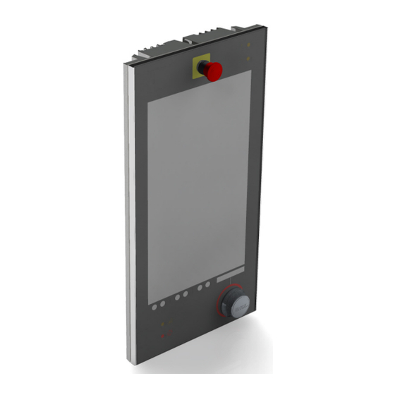
7. Product Description CC300 Operator Panel – User Guide 7.1. Front Side View Fig. 8: Front view of the CC300 operator panel Legend for Fig. 8: 1 On/Off button 7 Program interrupt button 2 RFID read/write zone 8 Rotary/push button (backlit) 3 21.5"... -
Page 20: On/Off Button
RFID antenna is mounted to the rear side of the front glass. RFID-equipped objects (e.g. ID cards, smart cards, RFID labels) can be read or written by the CC300 operator panel, when held against the front glass within the read/write zone. The RFID data will be processed by the installed software (e.g. user login with different authorizations for different user accounts). -
Page 21: Emergency Stop Switch
45 degrees by a linear actuator. By pressing the “Tilt out” button, the CC300 operator panel tilts outwards (with the lower edge ahead) until the button is released. When the maximum tilt angle of 45 degrees is reached, the tilt-out process will also be stopped. -
Page 22: Touch Display
CC300 Operator Panel – User Guide By pressing the “Tilt in” button, the CC300 operator panel tilts back (with the lower edge ahead) in the direction of the vertical mounting position until the button is released. When the vertical mounting position is reached, the tilt-in process will also be stopped. -
Page 23: Traversing Buttons
7. Product Description CC300 Operator Panel – User Guide 7.1.8. Traversing Buttons Fig. 13: Traversing buttons below the touch display Directly below the touch display, arranged in pairs, six traversing buttons are located, (see also Fig. 8, Pos. 4), which are processed by the capacitive touch of the display. The function of the buttons may be changed by the software;... -
Page 24: Rotary/Push Button With Display
7. Product Description CC300 Operator Panel – User Guide By pressing the capacitive program interrupt button (error acknowledgement button), all upcoming error messages will be acknowledged an a running automatic cycle will be interrupted. In idle mode, the program interrupt button and its related symbol are backlit white. The backlight changes to orange when the program interrupt button is pressed. -
Page 25: Rear View
7. Product Description CC300 Operator Panel – User Guide 7.2. Rear View Fig. 17: Rear side of the CC300 operator panel Legend for Fig. 17 : 1 Screws that secure the rear cover at the front 7 2x USB 2.0 ports... -
Page 26: Harting Connector
Power Supply via the Harting Connector 7.2.1.1. The power supply of the CC300 operator panel will be provided via pin 7 (24 Volts; cable No. 6) and pin 19 (0 Volts; cable No. 5) of the Harting connector. Control and Signal Lines 7.2.1.2. -
Page 27: Grounding Cable (Pe)
Grounding cable (yellow/green) Fig. 19: Grounding cable The CC300 operator panel must be grounded by establishing a large-area contact between the grounding cable (see also Fig. 17, Pos. 11) and an appropriate grounding contact. The cross section of the grounding cable is 6 mm 7.2.4. -
Page 28: Left And Right Side View
7. Product Description CC300 Operator Panel – User Guide 7.3. Left and Right Side View Fig. 21: Right side of the CC300 operator panel Fig. 22: Left side of the CC300 operator panel Legend for Fig. 21 and Fig. 22:... -
Page 29: Usb Ports
In a cavity at the left side of the aluminum cover, two USB 2.0 ports (see also Fig. 22, Pos. 7) are located. The cavity is deep enough that plugged-in USB sticks will not restrain the tilting mechanism of the CC300 operator panel. -
Page 30: Top And Bottom View
7. Product Description CC300 Operator Panel – User Guide 7.4. Top and Bottom View Fig. 24: Top view of the CC300 operator panel Fig. 25: Bottom view of the CC300 operator panel Legend for Fig. 23 and Fig.24: 1 Cable gland... -
Page 31: Accessing Internal Components
Before removing the cover of the CC300 operator panel in order to gain access to the internal components, the system must be powered down and the power cord has to be disconnected from the power source. -
Page 32: Fig. 26: Carefully Open The Cc300 A Few Inches
Front plate Soft underlayment Fig. 26: Carefully open the CC300 a few inches Attention: The device can only be opened fully after the auxiliary switch block (of the emergency stop switch) has been removed! (It is recommended that the rear cover is held by a second person while the auxiliary switch block is removed!) 4. -
Page 33: Fig. 28: Cc300 Operator Panel, Fully Opened
7. Product Description CC300 Operator Panel – User Guide 5. Now the CC300 operator panel can be folded apart carefully. Fig. 28: CC300 operator panel, fully opened Legend for Fig. 27: Circuit area above the display Position of the lithium battery on the CPU... -
Page 34: Closing The Cc300 Operator Panel
4. Fix the rear cover to the front plate with the 10x screws (M5 x 10) and bonded seals removed in chapter 7.5.1 “Opening the CC300 Operator Panel”, step 2 (see Fig. 17, Pos. 1). Do not exceed the maximum torque of x Nm when fastening the cabinet screws! (Value not yet defined!) Preliminary Version 0.2... -
Page 35: Maintenance And Prevention
1. Open the CC300 operator panel, as described in chapter 7.5.1 “Opening the CC300 Operator Panel”. 2. The lithium CMOS battery is located in a holder on the CPU board (mainboard) of the CC300 operator panel (see Fig. 28, Pos. 8 and Fig. 29). -
Page 36: Replacing The Emergency Stop Switch
Kontron Europe GmbH. The type of the lithium battery must be UL listed. 7. Close the CC300 operator panel as described in chapter 7.5.2 “Closing the CC300 Operator Panel”. Do not dispose of lithium batteries in general trash collection. Dispose of the battery according to the local regulations dealing with the disposal of these special materials, (e.g. -
Page 37: Firmware Updates
8. Maintenance and Prevention CC300 Operator Panel – User Guide 8.6. Firmware Updates 8.6.1. System BIOS Update Procedure To update the System BIOS the BIOS ROM File and the update tools shall be copied onto a bootable DOS USB Stick (no EMM386 or himem driver installed). -
Page 38: Technical Data
9. Technical Data CC300 Operator Panel – User Guide 9. Technical Data CC300 Operator Panel Technical Data System Customer-specific HMI panel PC with glass front Operating System ENGEL LINUX x86 64bit Cooling Concept Fanless system Cabinet Front: glass front with aluminum frame, Rear: die cast aluminum cover... -
Page 39: External Connectors And Interfaces
9. Technical Data CC300 Operator Panel – User Guide 9.1. External Connectors and Interfaces Interface Amount Position Data Type: 10/100/1000 Mbit LAN cable external Connector: RJ45 Source: CPU board DP cable Type: Display port external Connector:... -
Page 40: Electrical Specifications
9. Technical Data CC300 Operator Panel – User Guide 9.2. Electrical Specifications CC300 Operator Panel Electrical Data Power Supply 24VDC (+/- 20%), 3.5A max. Component Theoretical Value (Measured Value) CPU Board B754 (including CPU 847E) LCD Panel 23 (16) SSD 2x 3... -
Page 41: Environmental Specifications
9. Technical Data CC300 Operator Panel – User Guide 9.3. Environmental Specifications Thermal Management Passive Cooling (CPU and entire system) Operating Temperature +5 °C to +50 °C (41 °F to 122 °F) Storage/Transit Temperature -30 °C to +80 °C (-22 °F to 176 °F) Operating Rel. -
Page 42: Fig. 30: Dimensioned View Of The Cc300 Glass Front (Print Side - Reversed Image)
9. Technical Data CC300 Operator Panel – User Guide Fig. 30: Dimensioned view of the CC300 glass front (print side - reversed image) Preliminary Version 0.2... -
Page 43: Fig. 31: Dimensioned Rear And Side View Of The Cc300 Operator Panel
9. Technical Data CC300 Operator Panel – User Guide CC300 – Rear side Fig. 31: Dimensioned rear and side view of the CC300 operator panel Preliminary Version 0.2... -
Page 44: International Compliance, Approvals And Certificates
9. Technical Data CC300 Operator Panel – User Guide 9.5. International Compliance, Approvals and Certificates CE Directives Low Voltage Directive (Electrical Safety) 2006/95/EC EMC Directive 2004/108/EC RoHS II Directives 2011/65/EU Electrical Safety Standards EUROPE EN 60950-1 UL 60950-1 CB Scheme... -
Page 45: Interfaces - Pin Assignments
10. Interfaces – Pin Assignments CC300 Operator Panel – User Guide 10. Interfaces – Pin Assignments Low-active signals are indicated by a minus sign. 10.1.1. Harting Connector 24-pole Harting connector (Type Harting HAN 24 E, wire cross section: AWG 18) -
Page 46: Lan 0 Cable
10. Interfaces – Pin Assignments CC300 Operator Panel – User Guide 10.1.2. LAN 0 cable Pin Signal Name Standard Modular Plug (RJ45) MDI0+ MDI0- MDI1+ MDI2+ MDI2- MDI1- MDI33+ MDI3- (The LAN cable is connected to the LAN 0 port of the mainboard and led out of the cabinet.) 10.1.3. -
Page 47: Rs485 Cable
10. Interfaces – Pin Assignments CC300 Operator Panel – User Guide 10.1.4. RS485 Cable This cable is required for connecting an expansion panel. Pin Signal Name Direction 9-pin D-SUB Connector (female) IDENT# Out- RxD+ (Receive Data) TxD+ (Transmit Data++) NUM_IDENT#... -
Page 48: Dp Connector (Standard: Displayport 1.2)
10. Interfaces – Pin Assignments CC300 Operator Panel – User Guide 10.1.6. DP Connector (Standard: DisplayPort 1.2) Pin Signal Name 20-pin DP Connector ML LANE 0+ GND (ML LANE 0) ML LANE 0- ML LANE 1+ GND (ML LANE 1) -
Page 49: Usb Ports
10. Interfaces – Pin Assignments CC300 Operator Panel – User Guide 10.1.7. USB Ports Pin Signal Name 4-pin USB Connector Type A Version 2.0 +5V USB-A output (500mA max.) USB-A Data - USB-A Data + Ground The two externally accessible USB 2.0 ports are connected to the mainboard via cable. The 5V outputs are separately, electronically fused to 500mA each.
Need help?
Do you have a question about the CC300 and is the answer not in the manual?
Questions and answers
calibration screen