
Summary of Contents for Chattanooga Group ERGOSTYLE FX 5820
- Page 1 SERVICE MANUAL Model 5820- Manual Drops Model 5822- Auto Drops Applies to Serial numbers 1000 and above ISO 13485 Certifi ed © 2006 Encore Medical, L.P.
-
Page 2: Table Of Contents
TABLE OF CONTENTS Ergostyle ™ FX Tables FOREWORD ..........1 1 SAFETY PRECAUTIONS ......2 1.1 PRECAUTIONARY DEFINITIONS .. -
Page 3: Foreword
©2006 Encore Medical Corporation or its affiliates, Austin, Texas, USA. Any use of editorial, pictorial, or layout composition of this publication without express written consent from the Chattanooga Group of Encore Medical, L.P. is strictly prohibited. This publication was written, illustrated, and prepared for print by the Chattanooga Group of... -
Page 4: 1 Safety Precautions
Chattanooga Group Service Department for help. • The unit should be routinely checked before each use to determine all controls function normally. - Page 5 ErgoStyle FX table. Do not use from the outlet, and consult the dealer for repair accessories manufactured by other companies service. on the ErgoStyle FX. Chattanooga Group is not responsible for any consequence resulting • Do not use sharp objects such as a pencil point...
- Page 6 1 SAFETY PRECAUTIONS Ergostyle ™ FX Tables 1.2 PRECAUTIONARY INSTRUCTIONS (continued) C. Dangers • DO NOT connect the unit to an electrical supply without first verifying that the power supply is the correct voltage. Incorrect voltage may cause unit damage, malfunction, electrical shock, fire, or personal injury.
-
Page 7: 2 Nomenclature
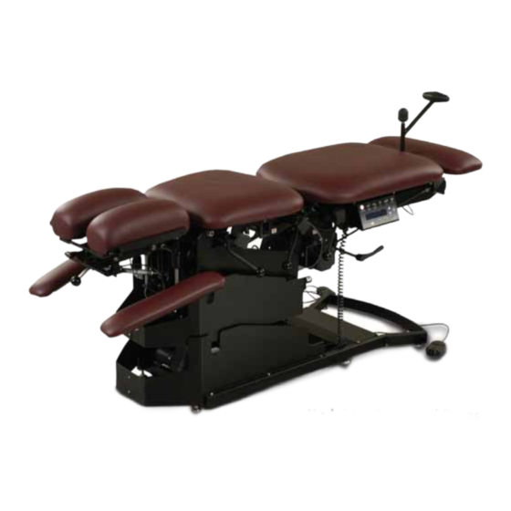
2 NOMENCLATURE Ergostyle ™ FX Tables 2.1 ERGOSTYLE FX TABLE EXTERNAL COMPONENTS The nomenclature graphics below, Figure 2.1, indicate Know the components and their functions before the general locations of the major components of the performing any operation of or service to the Ergostyle FX Table. -
Page 8: 3 Specifications
Air Compressor** (Not Provided) ............. 100 psi Minimum Operating Capacity Meets Directives: 93 /42 /EEC * Basic Table (Without Auto Flexion or Any Drops) IEC/UL/EN: 60601-1 ** Not available through Chattanooga Group. EN 60601-1-2 0 4 1 3... -
Page 9: 4 Troubleshooting
PC Boards. recommended nor will information or parts • Digital Inclinometer be supplied by Chattanooga Group. Any PC board component level troubleshooting performed will be at the sole risk and liability of the Service Technician performing such •... -
Page 10: Visual Inspection
4 TROUBLESHOOTING Ergostyle ™ FX Tables 4.2 VISUAL INSPECTION 4.4 LEAKAGE TESTS A. General Visually inspect the unit. A visual inspection can, to an experienced Technician, UNIT FAILING DIELECTRIC WITHSTAND AND/OR indicate possible abuse of the unit and LEAKAGE TESTS COULD INDICATE SERIOUS internal problems. -
Page 11: Power On/Off Test
Cord from the grounded power source. D. Test Result 1. If unit turns Off and On, unit passed test. 2. If unit does not turn Off and On, unit failed test. Contact Chattanooga Group to obtain Factory Service. 4.6 PATIENT INTERRUPT SWITCH TEST A. Specification Table stops when Patient Interrupt Switch is depressed. -
Page 12: 5 Removal And Replacement
5 REMOVAL & REPLACEMENT Ergostyle ™ FX Tables 5.1 POWER SUPPLY REMOVAL AND REPLACEMENT Unplug the unit from the power source before attempting removal or replacement procedures to prevent electrical shock. • Power Supplies retain High Voltage! POWER SUPPLY COVER A. - Page 13 5 REMOVAL & REPLACEMENT Ergostyle ™ FX Tables 5.1 POWER SUPPLY REMOVAL AND REPLACEMENT continued) Unplug the unit from the power source before attempting removal or replacement procedures to prevent electrical shock. • Power Supplies retain High Voltage! 3. Tilt the table so that access to the Power Supply Mounting Screws can be obtained.
-
Page 14: Daughter Board Removal And Replacement Manual Table Only
5 REMOVAL & REPLACEMENT Ergostyle ™ FX Tables 5.2 DAUGHTER BOARD REMOVAL AND REPLACEMENT MANUAL TABLE ONLY Unplug the unit from the power source before attempting removal or replacement procedures to prevent electrical shock. A. Part Numbers Daughter Board ..... . .58543 B. -
Page 15: Driver Board Removal And Replacement
5 REMOVAL & REPLACEMENT Ergostyle ™ FX Tables 5.3 DRIVER BOARD REMOVAL AND REPLACEMENT Unplug the unit from the power source before attempting removal or replacement procedures to prevent electrical shock. A. Part Numbers Driver Board ......58432 B. -
Page 16: Control Board Assembly Removal And Replacement Auto Flexion Only
5 REMOVAL & REPLACEMENT Ergostyle ™ FX Tables 5.4 CONTROL BOARD ASSEMBLY REMOVAL AND REPLACEMENT AUTO FLEXION ONLY Unplug the unit from the power source before attempting removal or replacement procedures to prevent electrical shock. A. Part Numbers Control Board Assembly ....58554 B. -
Page 17: Motor Removal And Replacement
5 REMOVAL & REPLACEMENT Ergostyle ™ FX Tables 5.5 MOTOR REMOVAL AND REPLACEMENT Unplug the unit from the power source before attempting removal or replacement procedures to prevent electrical shock. A. Part Numbers Motor ........58366 B. - Page 18 5 REMOVAL & REPLACEMENT Ergostyle ™ FX Tables 5.5 MOTOR REMOVAL AND REPLACEMENT continued) 6. Remove the Motor Mounting Hardware from the Motor Base and Rod. See Figure 5.14. MOTOR MOUNTING D. Motor Replacement HARDWARE Replace Motor in reverse order of removal.
-
Page 19: Drop Assembly Removal And Replacement
5 REMOVAL & REPLACEMENT Ergostyle ™ FX Tables 5.6 DROP ASSEMBLY REMOVAL AND REPLACEMENT REMOVE APPROPRIATE CUSHION Unplug the unit from the power source before attempting removal or replacement procedures to prevent electrical shock. A. Part Numbers Appropriate Drop . . .Refer to Section 7- Parts B. -
Page 20: 6- Calibration
6 CALIBRATION Ergostyle ™ FX Tables 6.1 FLEXION CALIBRATION AUTO FLEXION TABLES ONLY A. Specification Inclinometer dependent B. Equipment Required Calibrated Digital Inclinometer with an accuracy of ±0.50°. C. Calibration Procedure NOTE: Two people are required to perform this procedure. 1. -
Page 21: 7 Parts
7 PARTS Ergostyle ™ FX Tables 7.1 CONTROL BOARD ASSEMBLY ITEM PART DESCRIPTION 58554 Control Board Assembly... -
Page 22: Drops
7 PARTS Ergostyle ™ FX Tables 7.2 DROPS ITEM PART DESCRIPTION 95544 Lumbar and Pelvic Drop Assembly 95524 Thoracic Drop Assembly... -
Page 23: Head Piece Assembly
7 PARTS Ergostyle ™ FX Tables 7.3 HEAD PIECE ASSEMBLY NOTE: Cushions must be replaced in pairs. ITEM PART DESCRIPTION 58474 Head Piece- Tilt, ±20°, Fixed Cushions (Standard) 58476 Head Piece- Tilt, ±20°, Adjustable Cushions 58475 Head Piece- Tilt, ±20°, Forward and Toggle Drop, Adjustable Cushions 58473 Head Piece- Tilt, ±20°, 9"... -
Page 24: 8- Schematics
Ergostyle ™ FX Tables 8 SCHEMATICS Block Diagram 1 of 1... - Page 25 Ergostyle ™ FX Tables 8 SCHEMATICS Pneumatic 1 of 1...
- Page 26 Ergostyle ™ FX Tables 8 SCHEMATICS Driver Board- 58432 1 of 1...
- Page 27 Ergostyle ™ FX Tables 8 SCHEMATICS Control Board-58433 1 of 1...
- Page 28 Ergostyle ™ FX Tables 8 SCHEMATICS Daughter Board- 58543 1 of 1...
-
Page 29: 9 Warranty
UNITED STATES OF AMERICA, CANADA AND PUERTO RICO Chattanooga Group (“Company”) warrants that the ErgoStyle FX Table (“Product”) is free of defects in material and workmanship. This warranty shall remain in effect for one year (12 months) from the date of original consumer purchase. - Page 30 Ergostyle ™ FX Tables INTERNATIONAL Chattanooga Group (“Company”) warrants that the ErgoStyle FX Table (“Product”) is free of defects in material and workmanship. This warranty shall remain in effect for two years (24 months) from the date of original consumer purchase.
- Page 31 ISO 13485 Certifi ed 4717 Adams Road P.O. Box 489 Hixson, TN 37343 U.S.A. 1-423-870-2281 1-800-592-7329 U.S.A. 1-800-361-6661 CANADA +1-423-870-7200 OUTSIDE U.S.A +1 423-870-2046 OUTSIDE U.S.A. FAX chattgroup.com Medical Device Safety Service (MDSS) Burckhardtstr. 1 D-30163 Hannover Germany Telephone: +49-5103-939430 58558A ©...
Need help?
Do you have a question about the ERGOSTYLE FX 5820 and is the answer not in the manual?
Questions and answers