Table of Contents
Advertisement
10/09 AWB1230-1605
Operation and maintenance of
IZM low voltage air circuit breakers
IZM40
Purpose
This instruction leaflet is expressly intended to
cover the installation, operation, and maintenance
of IZM air circuit breakers. These circuit breakers
may be supplied as part of complete switchboard
assemblies or as separate components. This
manual applies only to the circuit breaker and (if
drawout) its mating cassette. IZM circuit breakers
may also be supplied as fixed-mounted devices. In
the case of fixed versions of IZM circuit breakers,
certain sections of this leaflet, referring to such
items as position interlocks and the drawout
mechanism, will not apply.
Trip units associated with IZM air circuit breakers
will be addressed in a general manner in this
leaflet. Specific trip unit details and time-current
characteristic curves are covered in separate
documents specific to the trip units.
IZM circuit breaker accessory items are discussed
briefly in this leaflet. Field installation instructions
for such items, however, are covered in individual
instruction leaflets specific to the accessory. This
information is also available from the Moeller Web
site at www.moeller.net/de/support.
For application information, consult Moeller or see
applicable Product Guides, Technical Documents,
Application Publications, and/or Industry Standards.
Effective October 2009
IZM97, IZM32, IZME40
Safety
All safety codes, safety standards, and/or
regulations must be strictly observed in the
installation, operation, and maintenance of
this equipment.
THE WarningS anD CaUTiOnS inCLUDED aS
ParT OF THE PrOCEDUraL STEPS in THiS LEaFLET
arE FOr PErSOnnEL SaFETY anD PrOTECTiOn
OF EQUiPMEnT FrOM DaMagE. an EXaMPLE OF
a TYPiCaL Warning LaBEL HEaDing iS SHOWn
aBOVE TO FaMiLiariZE PErSOnnEL WiTH THE STYLE
OF PrESEnTaTiOn. THiS WiLL HELP TO EnSUrE THaT
PErSOnnEL arE aLErT TO WarningS. in aDDiTiOn,
CaUTiOnS arE aLL UPPErCaSE anD BOLDFaCE.
All possible contingencies that may arise
during installation operation or maintenance,
and all details and variations of this equipment do
not purport to be covered by these instructions.
If further information is desired by purchaser
regarding particular installation, operation, or
maintenance of particular equipment, contact
the local Moeller representative.
IZM93, IZM20
Warning
Advertisement
Table of Contents

Subscribe to Our Youtube Channel
Related Manuals for Eaton IZM40


Summary of Contents for Eaton IZM40
-
Page 1: Purpose
10/09 AWB1230-1605 Effective October 2009 Operation and maintenance of IZM low voltage air circuit breakers IZM93, IZM20 IZM40 IZM97, IZM32, IZME40 Purpose Safety All safety codes, safety standards, and/or This instruction leaflet is expressly intended to cover the installation, operation, and maintenance regulations must be strictly observed in the of IZM air circuit breakers. -
Page 2: Table Of Contents
10/09 AWB1230-1605 Operation and maintenance of IZM low voltage air circuit breakers Effective October 2009 Contents Description Page Description Page Purpose ..........1 Section 4: Drawout circuit breaker and cassette . -
Page 3: List Of Figures
Operation and maintenance of 10/09 AWB1230-1605 IZM low voltage air circuit breakers Effective October 2009 List of figures Description Page Figure 1. Family of IZM Low Voltage Air Fixed and Drawout Circuit Breakers (800–6300A) ........6 Figure 2. - Page 4 10/09 AWB1230-1605 Operation and maintenance of IZM low voltage air circuit breakers Effective October 2009 List of figures (continued) Description Page Figure 50. Mechanical Trip Indicator with Associated Overcurrent Trip Switch ..........36 Figure 51.
-
Page 5: List Of Tables
Operation and maintenance of 10/09 AWB1230-1605 IZM low voltage air circuit breakers Effective October 2009 List of tables Description Page Table 1. IZM Circuit Breaker Ratings ................. 7 Table 2. -
Page 6: Section 1: Introduction
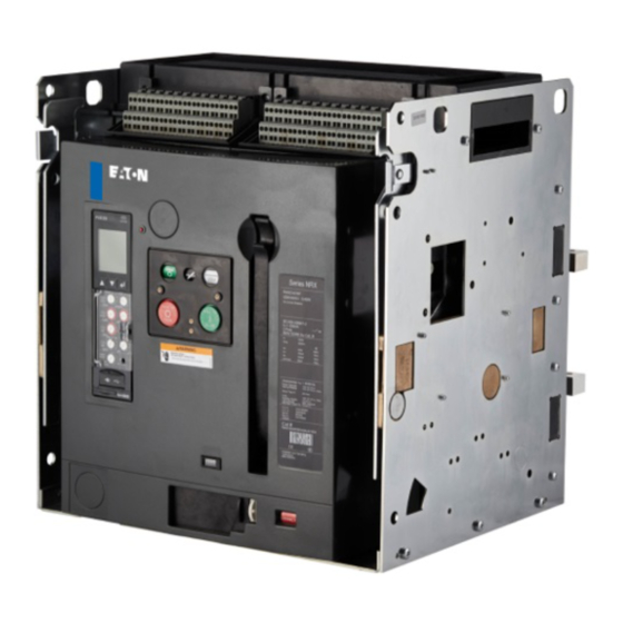
(REMOVE). The operating provide proper operating sequences. mechanism is a two-step stored energy mechanism, either manually or electrically operated. IZM93, IZM20 IZM40 IZM97, IZM32, IZME40 Figure 1. Family of IZM Low Voltage Air Fixed and Drawout Circuit Breakers (800–6300A) MOELLER www.moeller.net/de/support... -
Page 7: Safe Practices
Operation and maintenance of 10/09 AWB1230-1605 IZM low voltage air circuit breakers Effective October 2009 Table 1. IZM Circuit Breaker Ratings Maximum amperes Breaker Designation (ka) 1s/3s (ka) IZM93, IZM20 50/NA IZM93, IZM20 65/40 IZM97, IZM32 40/NA IZM97, IZM32 65/50 IZM97, IZM32 85/65 IZM97, IZM32... -
Page 8: Qualified Personnel
10/09 AWB1230-1605 Operation and maintenance of IZM low voltage air circuit breakers Effective October 2009 Qualified personnel Other publications and documentation For the purpose of operating and maintaining low voltage air In addition to this instruction manual, other printed information circuit breakers, a person should not be considered qualified if the and documentation is available and supplied as appropriate. -
Page 9: Section 2: Receiving, Handling, And Installation
Operation and maintenance of 10/09 AWB1230-1605 IZM low voltage air circuit breakers Effective October 2009 Section 2: Receiving, handling, and installation General information IZM air circuit breakers, when supplied as part of an assembly, may be shipped already installed in their respective breaker compartments. -
Page 10: Figure 4. Rear View Showing Current Sensor Rating Through Viewing Window
10/09 AWB1230-1605 Operation and maintenance of IZM low voltage air circuit breakers Effective October 2009 Table 2. Basic Circuit Breaker Weights Basic Circuit Breaker Weights (continued) Weights (kg) Weights (kg) Fixed Drawout Fixed Drawout iZM Product Typecoding 3-Pole 4-Pole 3-Pole 4-Pole iZM Product Typecoding 3-Pole... -
Page 11: Adapting Cassette
Operation and maintenance of 10/09 AWB1230-1605 IZM low voltage air circuit breakers Effective October 2009 Before attempting to push the circuit breaker into the DISCONNECT Molded Rail Supports position, compare the positioning of rejection interlock pins in the cassette with Table 3 and Figure 6 and the information supplied on the circuit breaker’s nameplate. -
Page 12: Figure 7. Remove Position
The outer (recessed) portion of the circuit breaker faceplate IZM99, IZM63 should align with the GREEN target line (labelled DISC) on the inside IZM99, IZM63, IZM40 top-left wall of the cassette (Figure 11). IZM99, IZM63 IZM99, IZM63, IZM40... -
Page 13: Figure 8. Disconnect Position
Operation and maintenance of 10/09 AWB1230-1605 IZM low voltage air circuit breakers Effective October 2009 Secondary Connection Not Made Rear of Compartment Compartment Front Door Circuit Primary Breaker Connections Side View Not Made Only Ground Connection Made • Breaker Still Behind Door •... -
Page 14: Fixed Circuit Breaker
10/09 AWB1230-1605 Operation and maintenance of IZM low voltage air circuit breakers Effective October 2009 CaUTiOn CONNECT CONNECT MakE CErTain THaT THE CirCUiT BrEakEr iS FULLY inSErTED inTO iTS COMParTMEnT BEFOrE anY aTTEMPT iS MaDE TO LEVEr THE CirCUiT TEST TEST BrEakEr. -
Page 15: Circuit Breaker Operation
Operation and maintenance of 10/09 AWB1230-1605 IZM low voltage air circuit breakers Effective October 2009 nOTiCE rEFEr TO THE CirCUiT BrEakEr WEigHTS in TABLE 2 TO EnSUrE THaT THE PanEL On WHiCH a FiXED CirCUiT BrEakEr iS TO BE MOUnTED iS CaPaBLE OF SUPPOrTing THE WEigHT. -
Page 16: Section 3: Circuit Breaker Description And Operation
10/09 AWB1230-1605 Operation and maintenance of IZM low voltage air circuit breakers Effective October 2009 Section 3: Circuit breaker description and operation Introduction IZM circuit breakers are available in physical frame sizes and in both IZM99 and IZM63 frame circuit breakers utilize six (or eight) sets drawout and fixed mounting configurations (Figure 14 and Figure of rear primary connections;... -
Page 17: Figure 15. Typical Fixed Circuit Breaker Features (Front And Rear Views)
Operation and maintenance of 10/09 AWB1230-1605 IZM low voltage air circuit breakers Effective October 2009 1–Baffled Arc Chute Cover 2–Secondary Disconnect 3–Faceplate (front cover) 4–Integral Lifting Handle 5–Fixed Horizontal Primary Terminal 6–Fixed Primary Terminal (with optional vertical adapter) 7–Arc Chamber 8–Sensor Rating Viewing Window 9–Mounting Foot 10–Circuit Breaker Nameplate... -
Page 18: Figure 16. Typical Izm63 And Izm99 Standard Frame Fixed Circuit Breaker Features (Front And Rear Views)
10/09 AWB1230-1605 Operation and maintenance of IZM low voltage air circuit breakers Effective October 2009 1–Baffled Arc Chute Cover 2–Secondary Contact Connector 3–Faceplate (front cover) 4–Integral Lifting Handle 5–Fixed Vertical Primary Terminals (with optional vertical adapter) 6–Arc Chamber 7–Mounting Foot 8–Circuit Breaker Nameplate 9–Phase Identification Labels 10–Tripper Bar... -
Page 19: Figure 17. Typical Izm Drawout Circuit Breaker Front Cover
Operation and maintenance of 10/09 AWB1230-1605 IZM low voltage air circuit breakers Effective October 2009 (Red) CLOSED (Green) OPEN (Yellow) CHARGED (White) DISCHARGED PUSH ON (Green) PUSH OFF (Red) CONNECT CONNECT TEST TEST DISCONNECT DISCONNECT Red = CONNECT Yellow = TEST Green = DISCONNECT 1–Trip Flag (pop-out indicator) 2–Three Accessory Windows... -
Page 20: Basic Circuit Breaker Assembly
10/09 AWB1230-1605 Operation and maintenance of IZM low voltage air circuit breakers Effective October 2009 Basic circuit breaker assembly The single contact finger performs both the main and arcing contact functions on different parts of the same finger (Figure 19). A highly IZM circuit breakers use a rigid frame housing construction of conductive alloy pad is part of the contact finger and functions as engineered thermoset composite resins. -
Page 21: Operating Mechanism
Operation and maintenance of 10/09 AWB1230-1605 IZM low voltage air circuit breakers Effective October 2009 Operating mechanism The IZM operating mechanism is based on the proven cam and spring design. It is easily accessed by removing four cover screws and the front cover (Figure 23). The mechanism is a two-step stored energy mechanism. -
Page 22: Arc Chambers
10/09 AWB1230-1605 Operation and maintenance of IZM low voltage air circuit breakers Effective October 2009 Anti-pump feature Electrically operated optional devices are available to automatically close or trip a manually operated circuit breaker. An electrical spring The IZM circuit breaker has both mechanical and electrical anti-pump release is available to close a manually operated circuit breaker. -
Page 23: Electronic Tripping System
Operation and maintenance of 10/09 AWB1230-1605 IZM low voltage air circuit breakers Effective October 2009 Integral Runner “V”-Shaped Plates Figure 26. Integral Arc Runner Viewed From Top of Arc Chamber (Arc Chute Removed, Circuit Breaker Closed) Arc chute The IZM arc chute mounts down over the arcing contact. Alternating V-shaped arc chute plates attract the arc and interrupt it. -
Page 24: Figure 28. Pictorial Diagram Of Typical Current Sensing, Processing, And Tripping System
10/09 AWB1230-1605 Operation and maintenance of IZM low voltage air circuit breakers Effective October 2009 Toroidal Current Sensor Rating Plug Trip Actuator Trip Unit Typical IZM Circuit Breaker Sensors otee: Alternate ground locations may be required to meet installation requirements. Figure 28. -
Page 25: Figure 29. Digitrip Rms 1150 Programmable Trip Unit Installed In Izm Circuit Breaker
Operation and maintenance of 10/09 AWB1230-1605 IZM low voltage air circuit breakers Effective October 2009 3. When it is required that the maximum ground fault pickup value not exceed 1200 amperes, a properly matched rating plug Pop-Out Trip Flag accomplishes this requirement for higher ampere sensors by incorporating circuitry to identify that level by sensor rating. -
Page 26: Secondary Contacts And Connection Diagrams
10/09 AWB1230-1605 Operation and maintenance of IZM low voltage air circuit breakers Effective October 2009 Trip actuator The trip actuator is a small cylindrically shaped electromagnetic device that acts mechanically to trip the circuit breaker in response to a signal from the trip unit. In general, it is comprised of a permanent magnet, a spring-loaded rod to produce the mechanical tripping, and a lever for resetting the actuator after tripping occurs. -
Page 27: Figure 33. Top View Secondary Connectors
Operation and maintenance of 10/09 AWB1230-1605 IZM low voltage air circuit breakers Effective October 2009 Fixed type circuit breakers—There are two secondary Secondary Connector Labels connection options: 1. Without terminal block—If a terminal block for customer use is not required, the circuit breaker is supplied with both plug-in connectors (male and female) just described in the two previous paragraphs. -
Page 28: Figure 37. Connection Diagram For Izm93 And Izm20, And Izm97 And Izm32 Frame With Digitrip 220/520/520M/520Mc
10/09 AWB1230-1605 Operation and maintenance of IZM low voltage air circuit breakers Effective October 2009 Figure 37. Connection Diagram for IZM93 and IZM20, and IZM97 and IZM32 Frame with Digitrip 220/520/520M/520MC (Type A, V, U Trip Units) MOELLER www.moeller.net/de/support... -
Page 29: Figure 38. Connection Diagram For Izm97 And Izm32 Frame With Digitrip 1150 (Type P Trip Unit)
Operation and maintenance of 10/09 AWB1230-1605 IZM low voltage air circuit breakers Effective October 2009 Figure 38. Connection Diagram for IZM97 and IZM32 Frame with Digitrip 1150 (Type P Trip Unit) MOELLER www.moeller.net/de/support... -
Page 30: Figure 39. Connection Diagram For Izm99 And Izm63 Frame With Digitrip 520/520M/520Mc With Abcabc Configuration
10/09 AWB1230-1605 Operation and maintenance of IZM low voltage air circuit breakers Effective October 2009 Figure 39. Connection Diagram for IZM99 and IZM63 Frame with Digitrip 520/520M/520MC with ABCABC Configuration (Type A, V, U Trip Units) MOELLER www.moeller.net/de/support... -
Page 31: Figure 40. Connection Diagram For Izm99 And Izm63 Frame With Digitrip 520/520M/520Mc With Aabbcc Configuration
Operation and maintenance of 10/09 AWB1230-1605 IZM low voltage air circuit breakers Effective October 2009 Figure 40. Connection Diagram for IZM99 and IZM63 Frame with Digitrip 520/520M/520MC with AABBCC Configuration (Type A, V, U Trip Units) MOELLER www.moeller.net/de/support... -
Page 32: Figure 41. Connection Diagram For Izm99 And Izm63 Frame With Digitrip 1150 With Abcabc Configuration (Type P Trip Unit)
10/09 AWB1230-1605 Operation and maintenance of IZM low voltage air circuit breakers Effective October 2009 Figure 41. Connection Diagram for IZM99 and IZM63 Frame with Digitrip 1150 with ABCABC Configuration (Type P Trip Unit) MOELLER www.moeller.net/de/support... -
Page 33: Figure 42. Connection Diagram For Izm99 And Izm63 Frame With Digitrip 1150 With Aabbcc Configuration (Type P Trip Unit)
Operation and maintenance of 10/09 AWB1230-1605 IZM low voltage air circuit breakers Effective October 2009 Figure 42. Connection Diagram for IZM99 and IZM63 Frame with Digitrip 1150 with AABBCC Configuration (Type P Trip Unit) MOELLER www.moeller.net/de/support... -
Page 34: Accessory Devices
10/09 AWB1230-1605 Operation and maintenance of IZM low voltage air circuit breakers Effective October 2009 Accessory devices A variety of accessory devices are available for use with IZM circuit breakers. Unless otherwise stated, they are all considered optional devices in the sense that they are not provided as standard on a manually operated circuit breaker. -
Page 35: Figure 46. Spring Release With Optional Latch Switch
Operation and maintenance of 10/09 AWB1230-1605 IZM low voltage air circuit breakers Effective October 2009 Table 7. Spring Release Ratings Table 8. Undervoltage Release Control Operational Voltage inrush Power Closing Operational Dropout inrush/Continuous Opening Voltages range 80–110% Consumption Time (ms) Control Voltage range Volts... -
Page 36: Figure 48. Shunt Trip, Spring Release, And Undervoltage Release Installed
10/09 AWB1230-1605 Operation and maintenance of IZM low voltage air circuit breakers Effective October 2009 Overcurrent Trip Switches Mechanical Trip Indicator Figure 48. Shunt Trip, Spring Release, and Undervoltage Figure 50. Mechanical Trip Indicator with Associated Overcurrent Trip Switch Release Installed Motor operator—A Motor operator is an electric motor assembly internally mounted in the circuit breaker (Figure 51 and Figure 52). -
Page 37: Figure 52. Motor Operator Installed In Izm93 An Izm20 Frame Circuit Breaker
Operation and maintenance of 10/09 AWB1230-1605 IZM low voltage air circuit breakers Effective October 2009 Operations Counter Lock Figure 53. Cover-Mounted Key Lock and Operations Counter Figure 52. Motor Operator Installed in IZM93 an IZM20 Frame Circuit Breaker Cassette lock—A cassette-mounted lock can be used in conjunction with different interlocking schemes (such as main- Mechanical accessories... -
Page 38: Figure 55. On-Off Pushbutton Lockable Cover Plate
10/09 AWB1230-1605 Operation and maintenance of IZM low voltage air circuit breakers Effective October 2009 Pushbutton cover—A padlockable cover is available to limit access to the ON and OFF pushbuttons (Figure 55). It can be installed with either or both pushbutton covers in place. Figure 57. -
Page 39: Figure 60. Door Escutcheon And Gasket
Operation and maintenance of 10/09 AWB1230-1605 IZM low voltage air circuit breakers Effective October 2009 Door escutcheon—The door escutcheon is a molded frame used Mechanical (pop-out) trip indicator—A red, pop-out mechanical to seal the space between the circuit breaker and the compartment trip indicator is an IZM feature. -
Page 40: Section 4: Drawout Circuit Breaker And Cassette
10/09 AWB1230-1605 Operation and maintenance of IZM low voltage air circuit breakers Effective October 2009 Section 4: Drawout circuit breaker and cassette General Section 3 discussed topics and features common to all IZM circuit breakers, no matter what the mounting configuration. In this section, features unique to the drawout configuration not covered elsewhere, including the drawout cassette, are covered. -
Page 41: Figure 64. Drawout Cassette Features (Front And Rear Views)
Operation and maintenance of 10/09 AWB1230-1605 IZM low voltage air circuit breakers Effective October 2009 Front View 1. Extension Rails 2. Extension Rail Cutout 3. Secondary Plug-in Connectors 4. Secondary Terminal Blocks 5. Arc Hood 6. Optional Cell (TOC) Switch 7. -
Page 42: Section 5: Fixed Circuit Breaker
10/09 AWB1230-1605 Operation and maintenance of IZM low voltage air circuit breakers Effective October 2009 Section 5: Fixed circuit breaker Horizontal Connection Optional Vertical Adapter General Section 3 discussed topics and features common to all IZM circuit breakers, no matter what the mounting configuration. In this section, features unique to the fixed configuration not covered elsewhere are covered. -
Page 43: Section 6: Inspection And Maintenance
Operation and maintenance of 10/09 AWB1230-1605 IZM low voltage air circuit breakers Effective October 2009 Section 6: Inspection and maintenance When to inspect Do not wait for specific scheduled periods to visually inspect the General equipment, if there are earlier opportunities. If possible, make a visual inspection each time a circuit breaker compartment door is ... -
Page 44: Figure 66. Izm Nameplate Information
10/09 AWB1230-1605 Operation and maintenance of IZM low voltage air circuit breakers Effective October 2009 Trip unit overload functional test This test uses the Digitrip 1150 self test function, the Digitrip Test Kit, or the hand-held IZM Functional Test Kit. Review test kit instructions for the trip unit. -
Page 45: Figure 68. Bottom View Of Arc Chute
Operation and maintenance of 10/09 AWB1230-1605 IZM low voltage air circuit breakers Effective October 2009 Arcing Contact (Toe) Integral Arc Runner Stationary Main Contact Moving Main Contact Alternating V-Shaped Plates Side View Figure 68. Bottom View of Arc Chute Figure 70. Contact Inspection Area with Circuit Breaker Open A contact wear indicator is provided for each primary contact and ... -
Page 46: Circuit Breaker Modifications And Changes
10/09 AWB1230-1605 Operation and maintenance of IZM low voltage air circuit breakers Effective October 2009 Contact Wear Indicator— Contact Wear Indicator— Contacts Closed and in Good Condition Contacts Closed and Wear is Indicated Side-to-Side Side-to-Side Ledge Ledge Contact Wear Inspection Area Contact Wear Inspection Area (ledge not visible under contacts) (ledge now becoming visible under contacts) -
Page 47: Figure 73. Current Sensor Cover In Place Over Sensors
Operation and maintenance of 10/09 AWB1230-1605 IZM low voltage air circuit breakers Effective October 2009 If the circuit breaker is a drawout configuration, the lower primary CaUTiOn disconnect finger clusters and the vertical adapters must first be TO PrEVEnT DaMagE TO THE raTing PLUg, DO nOT FOrCE iT inTO THE removed from frame sizes up to 2500A. -
Page 48: Section 7: Troubleshooting
10/09 AWB1230-1605 Operation and maintenance of IZM low voltage air circuit breakers Effective October 2009 Section 7: Troubleshooting Introduction Table 12 will help to determine the probable causes of simple companion publication, Moeller AWB1230-1609. If the problem cannot be resolved with the aid of one or both of these guides, circuit breaker problems and possible corrective actions. -
Page 49: Section 8: Renewal Parts
Operation and maintenance of 10/09 AWB1230-1605 IZM low voltage air circuit breakers Effective October 2009 Section 8: Renewal parts General All renewal parts and/or spare parts recommendations for IZM circuit breakers are supplied in the Moeller catalogue, not this instruction manual. -
Page 50: Izm Low Voltage Air Circuit Breakers Effective October
10/09 AWB1230-1605 Operation and maintenance of IZM low voltage air circuit breakers Effective October 2009 MOELLER www.moeller.net/de/support... - Page 51 Operation and maintenance of 10/09 AWB1230-1605 IZM low voltage air circuit breakers Effective October 2009 MOELLER www.moeller.net/de/support...
- Page 52 10/09 AWB1230-1605 Operation and maintenance of IZM low voltage air circuit breakers Effective October 2009 Moeller GmbH Industrieautomation ©2009 by Moeller GmbH Änderungen vorbehalten Subject to alterations 10/09 AWB1230-1605EN / Z8700 Moon/Doku/Heng Printed in USA (10/09)
Need help?
Do you have a question about the IZM40 and is the answer not in the manual?
Questions and answers