Table of Contents
Advertisement
Advertisement
Table of Contents

Summary of Contents for EURONOM ExoTrol MULTI C
- Page 1 Installation and user guide for ExoTrol MULTI C 1306-123EN Draft 1.0 ...
-
Page 2: Table Of Contents
Page | 2 Tabel of contents Introduction.................3 Exotrol Multi C ................3 System overview................4 Installation...................5 Hydralic system..................5 Heat pumps ........................5 Electrical installation ................5 High voltage connections ....................5 Low voltage connections ....................7 The display ................12 Menu system ..................13 Settings .........................14 Customer settings ..............................15 System configuration .............................. -
Page 3: Introduction
Page | 3 Introduction This manual is intended for Euronoms control unit Exotrol Multi C. Observe that this is only a draft manual with the most important information in order to get a function system. A complete manual will be released during October 2013 Exotrol Multi C Exotrol Multi is an advanced control system developed for use in bigger facilities and/or commercial buildings. The system is capable of controlling up to 8 heat pumps, 3 heating system, hot water recirculation, external power sources, solar panels etc and can also be added with integtrated energy measurements for both heat pumps and/or heating system/domestic hot water. From version 1.0 available from june 2013 maximum of connected heat pump is set to 3. Also from version 1.0 it’s only possible to control 1 type of tank solution, called 2‐tank system, with mixing valves. During 2013 different system solutions will be added. ... -
Page 4: System Overview
Page | 4 System overview Basic idea The system solution available from june 2013 can be explained schematic with below picture. One or more heat pumps operate to either of tank 1 or tank 2. This is controlled by the changing valve between the tanks. Energy is transferred to the heating system through 1 or more 4‐way mixing valves controlled by the control unit. Domestic hot water is provided by curled copper pipes, cold water preheated in tank 1 and after heated in tank 2. If necessary also a electric boiler can be connected in series with the tanks hot water supply. Tank 1 Tank 1 is the primary energy storage and supplier of heat to the heating system. As heating systems demands different temperatures depending on ambient conditions the temperature in tank 1 will be of a floating nature, i.e. temperature demand will be different depending on the conditions. This floating behavior is realized by using a heating curve that adapts to ambient conditions, mostly outdoor temperature. For each of the 3 heating system controls available, it’s possible to set a unique heating curve. Heat pumps will operate to the demanded temperature plus a set temperature difference. Tank 2 Tank 2 primary task is to provide enough temperature of the domestic hot water. As domestic hot water must be available independent of ambient conditions the temperature in this tank will be at a constant state, set condensation. Tank 2 is also used as a storage for any external energy sources connected, like electric heater, oil boilers etc. As 4‐way mixing valve is used also the heating system can use energy from tank 2 if the energy demand to heating system from tank 1 exceeds energy supply from the heat pumps. Heat pumps The heat pumps operate in a special way in order to supply correct temperature to the tanks at all times. This is called the VFC‐technology and means that the heat carrier flow is controlled by controlling a variable speed circulation pump. By controlling the flow also the flow temperature can be controlled and unlike standard systems, high temperature water can be supplied also with low return temperatures to the heat pumps. Tank 1 Tank 2 Heat pumps floating condensation condensation (Heating) (DHW) -
Page 5: Installation
Page | 5 Installation Hydralic system Regarding the hydraulic system (pipe dimension, valves etc.) please refer to the suppliers drawings. Heat pumps Refer to the manual shipped with the heat pump. Observe especially the chapter regarding setting the heat pump in Exotrol Multi mode. The setting “b” must be set to “3”. Also make sure that the setting CAN‐id is set unique for each heat pump, setting “C”. Heat pump 1‐> C=0 (CanID 0) Heat pump 2‐> C=1 (CanID 1) Heat pump 3‐> C=2 (CanID 2) Electrical installation High voltage connections Power supply 230V N PE, max 10A Number 1/2 – Radiator pump 1 Block used for the radiator pump to heating system 1. If a 3‐phase 400V pump is used this signal can be used as a maneuver signal to a contactor. ... - Page 6 Page | 6 Number 3/4/5- Mixing valve motor 1 Block used for the mixing valve motor to heating system 1. Number 6/7- Radiator pump 2 Block used for the radiator pump to heating system 2. If a 3‐phase 400V pump is used this signal can be used as a maneuver signal to a contactor. Number 8/9/10 – Mixing valve motor 2 Block used for the mixing valve motor to heating system 2. Number 11/12 – Radiator pump 3 Block used for the radiator pump to heating system 3. If a 3‐phase 400V pump is used this signal can be used as a maneuver signal to a contactor. Number 13/14/15 – Mixing valve motor 3 Block used for the mixing valve motor to heating system 3. ...
-
Page 7: Low Voltage Connections
Page | 7 Low voltage connections Number 1/2 – CAN communication The CAN cable should be connected in series with the heat pumps. Observe the termination jumpers on the circuit board in the heat pumps. Only the last in the series should have termination jumpers mounted. The CAN‐cable also have a shield that should be connected on all points, both heat pumps and in the Exotrol Multi . No other cable than approved CAN‐BUS cable is allowed. No termination No termination No termination Termination Multi‐ LogiQ Heatpump 1 Heatpump 2 Heatpump 3 Not terminated Terminated Number 3/4 –... - Page 8 Page | 8 Number 9/10 /11/12– Room sensor 2 Room sensor 2 is arbitrary to install. If installed it can adjust the set heating curve for heating system 2 and thereby improve system efficiency. However, it demands a central place in the building in order to function well. Number 13/14 – Temp sensor tank 1 Temp sensor tank 1 should be installed in tank 1. Placing is of great importance as the heat pumps will operate according to this temperature. Installation in a pocket is recommended; avoid mounting on the tank shell. Mount the sensor somewhere between 1/2 to 1/3 from the bottom, see picture below. Number 15/16 – Temp sensor tank 2 Temp sensor tank 2 should be installed in tank 2. Placing is of great importance as both the heat pumps and external power sources will operate according to this temperature. Installation in a pocket is recommended; avoid mounting on the tank shell. If electric heaters are installed the sensor must be placed above them. Mount the sensor somewhere between 1/2 to 2/3 from the bottom, see picture below. Tank 1 Tank 2 ...
- Page 9 Page | 9 Number 23/24 – Temp sensor hot water recirculation There are different ways to control hot water recirculation directly from Exotrol Multi . One way is to measure the temperature on the domestic hot water pipe and thereby decide when the circulation pump needs to operate. If using this method the sensor must be installed. Place the sensor on the hot water recirculation return pipe at least 1m from tank 2 (or electric boiler). Insulate well. Number 25/26 – Temp sensor solar panel system 1 Not implemented Number 27/28 – Temp sensor solar panel system 2 Not implemented Number 29/30 – Temp sensor extra 1 Not used ...
- Page 10 Page | 10 Number 42/43/44/45 – Current transformers Not implemented Number 46/47 – Limit switch mixing valve motor 1 If the mixing valve motor is equipped with a limit switch it’s possible to set a time delay before the mixing valve get permission to collect energy from tank 2 and thereby improve system efficiency. It’s recommended but not necessary to install in order to get the system running. Number 48/49 – Limit switch mixing valve motor 2 If the mixing valve motor is equipped with a limit switch it’s possible to set a time delay before the mixing valve get permission to collect energy from tank 2 and thereby improve system efficiency. It’s recommended but not necessary to install in order to get the system running. Number 50/51– Limit switch mixing valve motor 3 If the mixing valve motor is equipped with a limit switch it’s possible to set a time delay before the ...
- Page 11 Page | 11 Number 64/65– Solid state output Not implemented Number 66/67– Analog in 1 Not implemented Number 68/69– Analog in 2 Not implemented Number 70/71– Analog out 1 Not implemented Number 72/73/74 – Flow meter heating system 1 Not implemented Number 75/76/77 – Flow meter heating system 2 Not implemented ...
-
Page 12: The Display
Page | 12 The display The display contains 4 buttons and has different functionality depending on what page in the menu system that is active. Above every button symbols describe what function the button has in the present view. In general the first button (from left) is used to enter menus, to escape/go back in the different views. A short push for enter menus and a long push in order to go back. Buttons in the middle (up/down) is used to choice where to enter or when setting values Button to the right is used to confirm settings. There are 2 modes for the display: Graphical system overview This mode is shown when no menu is entered. The system will show actual values and settings in the system. Menu system This mode is entered by pushing the left button short. First show is the main menu described in next chapter ... -
Page 13: Menu System
Page | 13 Menu system Main menu have the following head texts: > Settings History Manual Control Language SystemInfo Settings In this entry all possible settings of the system, both customer, installer and service, is adjusted. History History contains all information that the system collects during operation, for example operation times, energy consumption etc. Manual Control This entrance is protected by code and should only be used of service technicians or educated installers ... -
Page 14: Settings
Page | 14 Settings Settings menu have the following sub menus > Customer settings System configuration Advanced settings Display Factory reset Clear times Reset errors Customer settings In this entry settings for the customer is available. For example adjusting the heating curves. System configuration System configuration must be entered by the installer in order to start the system. In this menu the system will be informed what components that are installed and how it’s configured. For example how many heating system that will be controlled. ... -
Page 15: Customer Settings
Page | 15 Customer settings Customer settings have the following sub menus. > Heating system 1 Heating system 2 Heating system 3 Hot water settings Heating system 1 Settings for heating system 1 Heating system 2 Settings for heating system 2 Heating system 3 Settings for heating system 3 Hot water settings ... - Page 16 Page | 16 Heat curve point A There are 3 basic settings for the heating curve, points A, B and C. With these 3 points, you can adjust the gradient and vertical position. The aim is always to set the curve as low as possible. Point A describes the temperature of the water to be sent to the heating system if the outdoor temperature is ‐15°C. The factory default setting for this item is 55°C. In other words, when it is ‐15°C outside, the mixing valve open in order to transmit 55°C hot water to the heating system. When you adjust this point, you change the angle of the entire heating curve. The biggest changes occur when outdoor temperatures are cold ‐ see the graph below. Adjusting point A on the heating curve. (The factory default setting 55° C is marked with a cross) ‐30 ‐25 ‐20 ‐15 ‐10 ‐5 Outdoor temperature ...
- Page 17 Page | 17 Heat curve point B Adjusting point B means that the entire heating curve moves upwards or downwards (parallel movement). In other words, you don't adjust the gradient for any particular outdoor temperature, rather you adjust the curve for the entire outdoor temperature range. The factory default setting is 0°C, i.e. no movement at all. If you increase this value, the curve moves upwards, i.e. becomes warmer, and if you reduce this value, the temperature drops. Adjusting point B on the heating curve. ‐30 ‐25 ‐20 ‐15 ‐10 ‐5 Outdoor temperature ...
- Page 18 Page | 18 Heat curve point C Point C has 2 meanings. On the one hand, it is used to adjust the gradient of the heating curve during warmer outdoor temperatures, but it is also used as a "shutoff temperature" for the heat to the heating system. When the outdoor temperature reaches this temperature and stays there for at least 8 hours, the mixing valve closes fully and the radiator pump is set off, i.e. no heat is sent to the heating system. During summer time when heat is in off‐mode both circulation pump and mixing valve, which determines the temperature to the heating system, will be run periodically in order to prevent sticking. Adjusting point C on the heating curve. (The factory default value of +17°C is marked with a cross). ‐30 ‐25 ‐20 ‐15 ‐10 ‐5 Heating system ...
- Page 19 Page | 19 Cracking of heat curve When the outdoor temperature is around 0°C and it is very windy, slightly warmer water may sometimes need to be sent to the heating system. We call this adjustment, when the outdoor temperature is 0°C, cracking the curve. If you feel that there isn't enough heating when it is around 0°C outside, but it is otherwise sufficient, you can increase this setting somewhat. Adjusting the cracking point. (The factory default value is 0) ‐10 ‐9 ‐8 ‐7 ‐6 ‐5 ‐4 ‐3 ‐2 ‐1 Outdoor temperature ...
- Page 20 Page | 20 Max temp heating system Points A, B and C are all used to set the curve in different positions. There are also settings for the max and min temperature that will be sent to the heating system. These settings do not affect the gradient or the position of the heating curve. Instead, they restrict the curve and allow you to set a minimum and maximum temperature that is sent to the heating system. Max temperature is mainly used to prevent too hot water to enter an under floor heating system This setting limits the heating curve and sets the maximum temperature at which water can be sent to the heating system, regardless of how cold it is outside. ‐30 ‐25 ‐20 ‐15 ‐10 ‐5 Outdoor temperature ...
- Page 21 Page | 21 Min temp heating system The min temperature setting allows you to cancel the function described in point C, "heat off", which means that the mixing valve stops sending energy to your heating system. If you activate basement heating, Exotrol Master will continue to send water at the temperature you set, even if the outdoor temperature is above the set point. The function is activated if the set temperature is above 10C. ‐30 ‐25 ‐20 ‐15 ‐10 ‐5 Outdoor temperature ...
- Page 22 Page | 22 Hot water settings This menu gives possibility to set temperatures in the tanks that affect the hot water comfort. Max tank temperature This setting decides the set temp that tank 2 will hold at all conditions. Observe that higher values will decrease system efficiency and possibly make it impossible for the heat pumps to charge the tank. Always start at default setting (53C) and increase later if higher domestic hot water temperatures is needed. Min tank temperature This setting decides the lowest allowed temperature in tank 1. As tank 1 operates according to the heating curve the temperature will differ dependent on ambient conditions. At summer time there’s no or small heating need and therefore no meaning to keep a high temperature for the heating system. However, tank 1 is also used for pre heating of the domestic hot water. This setting set the lowest temperature that tank 1 will have at all conditions, despite the heating curve. ‐30 ‐25 ‐20 ‐15 ‐10 ‐5 Outdoor temperature ...
-
Page 23: System Configuration
Page | 23 System configuration System configuration must be entered by the installer in order to start the system. In this menu the installed system will configured. The menu is code protected. Code: 3 5 5 0 The configuration menu has 4 submenus: > Heat pumps Heating system Solar system Communication Heat pumps ... - Page 24 Page | 24 Heating system There are 13 settings available in this menu: Number of heating system Set the number of installed heating systems (mixing valves). External power sources Set the number of installed external power sources that should be controlled by Exotrol Multi Current sensors installed Not used Room sensor heating system 1 Set to “1” if room sensor for heating system 1 is installed in the system Room sensor heating system 2 Set to “1” if room sensor for heating system 2 is installed in the system Floor heating only in heating system 1 If heating system 1 has floor heating only this setting should be set to “1”. It will change default settings for maximum temperature to the heating system. Floor heating only in heating system 2 If heating system 2 has floor heating only this setting should be set to “1”. It will change default settings for maximum temperature to the heating system. Floor heating only in heating system 3 If heating system 3 has floor heating only this setting should be set to “1”. It will change default settings for maximum temperature to the heating system. Number of solar systems ...
-
Page 25: Advanced Settings
Page | 25 Allow external power source 3 If at least 3 external power sources are installed (in previous settings) this setting will be activated. Here it’s possible to allow or block operation of the installed source. Advanced settings The advance settings menu is code protected and should be used only by installer and/or service technician. Depending on the choices in the system configuration menu different views will be available. Code: 7 9 0 2 Available sub menus: > Heat pumps Accumulator tanks Heating system Hot water recirculation External power sources Solar system Calibration (not heat pumps) ... - Page 26 Page | 26 Heat pumps First choice when entering this menu is a list with all installed heat pumps. Choose the heat pump where the settings should be changed. > Heat pump 1 (Exotic 17) Heat pump 2 (Exotic 10) Heat pump 3 (Polaris 20) Heat pump 4 Heat pump 5 Heat pump 6 Heat pump 7 Heat pump 8 ...
- Page 27 Page | 27 Calibration of flow temperature sensor Calibration of sensor Calibration of return temperature sensor Calibration of sensor Calibration of hot gas temperature sensor Calibration of sensor Calibration of defrost temperature sensor (A/W heat pumps only) Calibration of sensor Calibration of brine out temperature sensor (B/W heat pumps only) Calibration of sensor Calibration of brine in temperature sensor (B/W heat pumps only) Calibration of sensor Calibration of current sensor (B/W heat pumps only) Calibration of current sensor (electronic motor protector) Freezing alarm temperature for brine fluid (B/W heat pumps only) This setting makes it possible to set the lowest permitted temperature on the brine fluid. If the temperature (measured on brine out) gets below this temperature the heat pump will stop and warn for too low brine temperature Max temperature difference brine in/out (B/W heat pumps only) Setting for controlling that the flow on brine side isn’t too poor. If the difference between brine in and out sensor exceeds set value the heat pump will stop and warn for poor flow on brine side. Autorun brine circulation pump for 48 hours (B/W heat pumps only) After installation this setting can be used in order to help air venting the brine circuit. When activated brine circulation pump will run for 48 hours independent on if the compressor is running or not. PI‐regulator settings for charge pump The charge pump operates with variable speed dependent on requested flow temperature. The control is achieved with a software PI‐regulator. It might in some cases be necessary to adjust the parameters of the regulator depending on the hydraulic installation. There are 3 different settings available, see below. Contact the reseller before changing any of these parameters PGain for PI‐regulator to pwm charge pump Gain for the regulator. Increased values will fasten the control but can result in overshooting and possible high pressure cut out. ...
- Page 28 Page | 28 IGain for PI‐regulator to pwm charge pump Integral part for the regulator. This part will increase the regulator signal every 15 seconds as long as the set value isn’t reached. If increased to much overshooting will be the result. Minimum allowed flow for pwm charge pump The charge pump has, dependent on the hydraulic installation, a minimum flow that can be achieved. Long pipe installations and bows will increase the pressure drop and thereby the minimum flow might be necessary to increase. (Observe that the setting is only a estimation of the flow) Accumulator tanks Following settings is available > Restart hysteresis tank 1 Restart hysteresis tank 2 Tempdiff between heat pumps Step time between heat pump Max temp diff tank 1/heat pump Max temp diff tank 2/heat pump Max operation time tank 1 Max operation time tank 2 ...
- Page 29 Page | 29 Nominal value tank Restart hysteresis Start heat pump 1 Step time Start heat pump 2 Step time Start heat pump 3 Step time Start heat pump 4 Temp diff Step time between heat Start heat pump 5 pumps Step time Start heat pump 6 Step time Start heat pump 7 Step time Start heat pump 8 Max temp diff tank 1/heat pump Before any heat pump is started a control is done in order to check if it’s possible for the heat pump to operate to any of the tanks. This check is done by comparing the actual value on the tank sensor and the maximum temperature that the heat pump can provide at the given point. The setting gives the minimum temperature difference between the tank temperature and the heat pumps max flow temperature. If for example the max allowed flow temperature for the heat pump is 59C and the set value is 8C it gives that the maximum allowed temperature in the tank can be 59‐8C=51C in order for the heat pump to start. The same control is done when the system is switching between charging tank 1 and tank 2. Max temp diff tank 1/heat pump Same analogy as max temp diff tank 1/heat pump ...
- Page 30 Page | 30 Max heat pump temp Start/changing Max tempdiff not possible Start/changing possible Max operation time tank 1 If there’s a heating need in both tank 1 and tank 2 the latter will be charged first. However it’s possible to set a maximum time for charging any of the tanks if there’s a need in the other on. When the time has passed the system will switch to the other tank and operate until the need is fulfilled or until the max operation time has passed. Max operation time tank 2 Same analogy as max operation time tank 1 ...
- Page 31 Page | 31 Heating system Following settings are available in this menu > Time delay mixing valve 1 Time delay mixing valve 2 Time delay mixing valve 3 Temp diff heating curves&tank1 Time delay mixing valve 1 If a mixing valve motor with a limit switch is installed it’s possible to set a time delay before the mixing valve gets permission to open to tank 2. This function gives the heat pumps longer time to fulfill the energy need to the heating system instead of opening to the more expensive energy in tank2. Time delay mixing valve 2 Same analogy as time delay mixing valve 1 ...
- Page 32 Page | 32 Hot water recirculation Following settings are available in this menu > Function choice Temperature control Time control – cycle time Time control – period time Function choice In this setting there are 4 different choices: 1. Recirc off Hot water recirculation pump inactivated 2. Always on Hot water recirculation pump is always on 3.
- Page 33 Page | 33 External power sources Following settings are available in this menu > External power source 1 External power source 2 External power source 3 Delay time power source 1 Step time between source 1&2 Step time between source 2&3 Main fuse Step model External power source 1,2,3 Following settings are available in this submenu (same for source 1, 2, 3) > Type of source ...
- Page 34 Page | 34 Delay time power source 1 It’s possible to set a time delay that delays the start of power source 1 even if the restart hysteresis is fulfilled. Step time between source 1&2 This setting provides a possibility to start power source 2 even if the hysteresis isn’t fulfilled. When source 1 starts the time starts to count. When the time has passed source 2 will be activated Step time between source 2&3 Same analogy as step time between source 1&2 Main fuse Not used Step time between source 2&3 Same analogy as step time between source 1&2 Step model There are 2 different models for the control of external power sources. Model A and model B. See figure below. Nominal value tank 2 Restart hysteresis source 1 Source 1 STEPMODEL A Restart hysteresis Source 1 Source 2 source 2 Restart hysteresis source 3 Source 1 Source 2 Source 3 ________________________________________________________________________________ ...
- Page 35 Page | 35 Calibration This menu contains calibration of all sensors used in the heating system (not heat pump sensors). Depending on how the system is configured different view will be available. Following sensors can be calibrated in this version: ‐ Tank sensor tank 1 ‐ Tank sensor tank 2 ‐ Flow temp sensor heating system 1 ‐ Flow temp sensor heating system 2 ‐ Flow temp sensor heating system 3 ‐ Room sensor heating system 1 ‐ Room sensor heating system 2 ...
-
Page 36: History
Page | 36 History The history menu have 3 submenus > Operation heat pumps Operation ext power sources Alarm history heat pumps Operation heat pumps Following sub menus are available > ... -
Page 37: Operation Ext Power Sources
Page | 37 Operation ext power sources Following sub menus are available > Total energy consumption Average power Energy consumption last 24h Average power last 24h Total energy consumption Total energy consumption is shown for each of the power sources. The calculation is based from the set value of the estimated power of each source. The view also shows the total operation time for the external sources ... - Page 38 Page | 38 Energy consumption last 24h Same analogy as for total energy consumption but calculated for the last 24h. Also operation times last 24h is shown Time last 24h source 1 7h54min Energy source 1 (el.heat) 154kWh Time last 24h source2 2h15min Energy source 2 (el.heat) 83kWh Time last 24h source 3 1h04min Energy source 3 (oil) 45kWh Average power last 24h Same analogy as for total average power but calculated for the last 24h. Energy source 1 (el.heat) 7,2kW Energy source 2 (el.heat) 6,8kW Energy source 1 (oil) 2,1kW ...
-
Page 39: Alarm History Heat Pumps
Page | 39 Alarm history heat pumps When entering this menu an overview with all installed heat pumps and number of logged errors. Alarms > Heat pump 1 (Exotic 17) 5 Heat pump 2 (Exotic 10) 4 Heat pump 3 (Polaris 20) 2 Heat pump 4 Heat pump 5 Heat pump 6 Heat pump 7 ... -
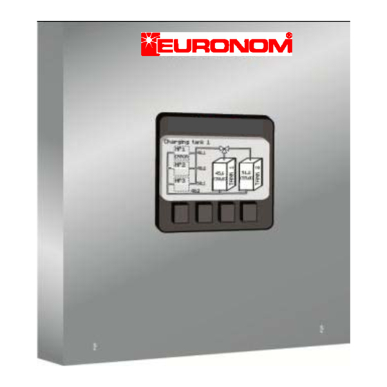
Page 40: Graphical System Overview
Page | 40 Graphical system overview This chapter handle all the graphical pages that shows the different system parameters and the actual values in the system. To scroll between the shows use the up/down buttons. Charging tanks This page shows the heat pump operation to tank 1 or tank 2. When charging is running the flow will be simulated to the tank which is charged. If an error is present in a heat pump the text “ERROR” will be shown inside the heat pump box. Information text Flow temperature Tank temp heat pumps Nominal value tank Return temp heat pumps... -
Page 41: Heating System Operation
Page | 41 Heating system operation This page is available for each of the heating systems (max 3) and shows temperatures sent to the heating system and the mixing valve behavior etc. The flow from the tanks through the mixing valve will be simulated. Information text Primary flow temperature Nominal value flow temp Tank temp Nominal value tank Limit switch mixing valve activated or not. Out door temp Time left before opening mixing valve to tank 2... -
Page 42: Tank Charge Control
Page | 42 Tank charge control This page provides information of the different settings controlling the charging of the tank. These parameters have been explained in the settings menu chapter. ... -
Page 43: Heating Curve
Page | 43 Heating curve This page provides information of the settings of the heating curve and is available for all of theheating systems (max 3). A majority of these settings is done in customer menu, please see chapter “Customer settings”. ... -
Page 44: External Power Sources
Page | 44 External power sources This page provides information on the status for external power sources if installed. Both settings and actual values are shown. ... -
Page 45: Heat Pumps
Page | 45 Heat pumps Every installed heat pump has its own page where all parameters and current status is shown. Depending on heat pump model the pages differ. ExoAir Model SerialNr Compressor current Heat pump 1 – ExoAir 10,5 – S/N:134623214 Max compressor current Hot gas temp Fan status Flow temp H=High, L=Low Max flow temp Outdoor temp PWM charge Temp for pump flow activetion of ... -
Page 46: Exotic
Page | 46 Exotic Compressor Model SerialNr current Max compressor Heat pump 1 – Polaris 14 – S/N : 264623214 current Hot gas temp Brine out temp Flow temp Brine freeze alarm Max flow temp PWM brine PWM charge pump flow pump flow Return temp... -
Page 47: R/T Tables Sensors
Page | 47 R/T tables sensors Temperature sensor Hot gas sensor (only for heat pump) Temp Temp Temp Temp R (kΩ) R (kΩ) R (kΩ) R (kΩ) (°C) (°C) (°C) (°C) ‐15 11,50 21 2,34 0 163.4 72 8.2 ‐14 10,94 22 2,25 2 147.6 ... - Page 48 Page | 48 Visiting and delivery address: Franska vägen 12 393 56 KALMAR • SWEDEN Telephon +46(0)480 221 20 Telefax +46(0)480 870 17 www.euronom.se info@euronom.se ...
Need help?
Do you have a question about the ExoTrol MULTI C and is the answer not in the manual?
Questions and answers