Advertisement
Quick Links
Advertisement

Related Manuals for Ashton AWM250

Summary of Contents for Ashton AWM250
- Page 1 User Manual...
- Page 2 Care Instructions ................................3 Product Specifications ..............................4 Instructions For Use ..............................5 Troubleshooting ................................6 Specific Product Features: AWM250 ........................... 7 Specific Product Features: AWM350 ........................... 9 Specific Product Features: Handheld Transmitter ......................11 Specific Product Features: Bodypack Transmitter ......................12...
- Page 3 Improper installations of this type create the possibility of fire and a general safety hazard. IMPORTANT NOTE: To reduce the risk related to the correct and normal use of the product, all Ashton products are accurately tested in a safety laboratory. Do not modify the present unit, the safety standard and the instrument’s performance could be compromised, and as a further consequence the warranty will be revoked.
- Page 4 85mm (H) x 65mm (W) x 24mm (D) >55dB WEIGhT DIMENSIONS 87 grams (without batteries) AWM250: 44mm (H) x 410mm (W) x 180mm (D) AWM350: 45mm (H) x 482mm (W) x 160mm (D) POWER REqUIREMENTS 2 x AA” size alkaline or rechargeable batteries WEIGhT...
- Page 5 INSTRUCTIONS FOR USE 1. Take transmitter out of box. Screw the antenna into A and B Jacks. Plug audio cable into channel XLR output socket and connect other end into desired speaker or other output source. Place all applicable batteries into receivers. 2.
-
Page 6: Troubleshooting
TROUBLEShOOTING PROBLEM LED STATUS SOLUTION The LED of the transmitter is off Slide the transmitter’s power switch to ON. Make No sound or faint sure battery terminals match transmitter terminals. sound The LED of the receiver is off Make sure to attach the power adaptor to the DC input in the back of the receiver and attach the other end to a wall power socket. - Page 7 3. 1/4 inch mix output socket 6. Antenna jack A AWM250 FREqUENCy SELECTION AWM250 PRODUCT USE TIPS Many regions have strict management on the • Maintain a line of sight between the transmitter and frequency of the radio. This system provides receiver.
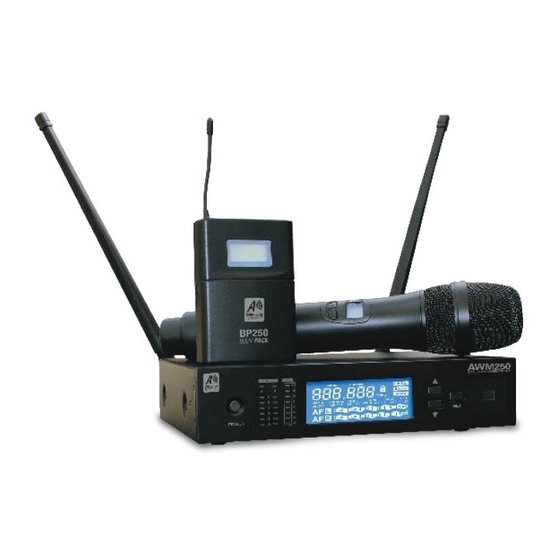
- Page 8 AWM250 SySTEM COMPONENTS The AWM250 system components include: Guitar System includes: 1. Receiver 1. Bodypack transmitter 2. AA batteries 2. 1/4’ connector and 3. Audio cable mini 3-plug in 4. Power adaptor 5. Antenna handheld Transmitter: Bodypack Transmitter: 1. Transmitter 2.
- Page 9 AWM350 PANEL FRONT PHONES POWER 1. Power Switch 6. Channel 1 AF LED 11. Signal send button 2. Channel A receiving 7. Channel 1 LCD 12. Infrared (IR) window - 3. Channel A RB LED 8. Menu up select button sends the IR signal 4.
- Page 10 AWM350 SySTEM COMPONENTS The AWM350 system components include: Guitar System includes: 1. Receiver 1. Bodypack transmitter 2. AA batteries 2. 1/4’ connector and 3. Audio cable mini 3-plug in 4. Power adaptor 5. Antenna PHONES POWER handheld Transmitter: Bodypack Transmitter: 1.
- Page 11 hANDhELD TRANSMITTER SPECIFICATIONS FUNCTIONS 1. Grill 2. LCD display 3. Power switch Power ON / OFF the transmitter. 4. MUTE button Touch to change between MUTE active status. 5. IR Port Match the frequency between this product and the receiver to match levels. Each product will occupy one infrared port when multi-system is in use.
- Page 12 BODyPACK TRANSMITTER SPECIFICATIONS FUNCTIONS 1. Antenna 2. LCD display 3. Power Hold to change power ON / OFF 4. POWER / IR indicator Green: Active Flashing Red: IR transmitting enabled Solid Red: Low battery power 5. Mic in 6. Channel selection button 7.
Need help?
Do you have a question about the AWM250 and is the answer not in the manual?
Questions and answers