Table of Contents
Advertisement
Quick Links
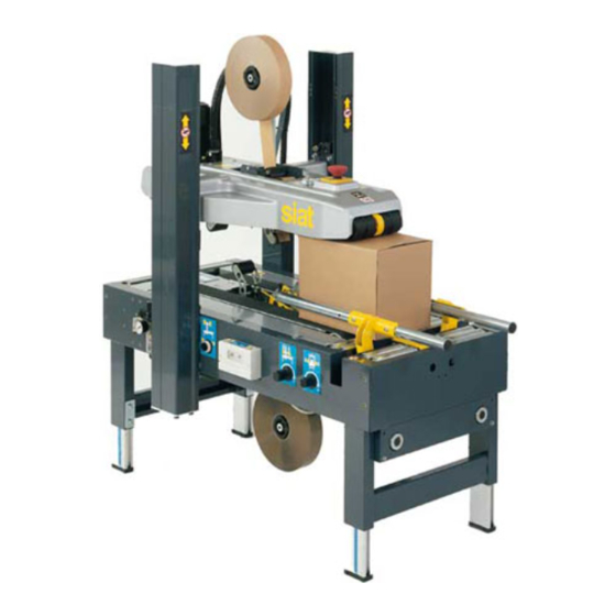
SR4-S
NASTRATRICE AUTOMATICA
AUTOMATIC CASE SEALING MACHINE
MACHINE ENRUBANNEUSE AUTOMATIQUE
AUTOMATISCHE KARTONVERSCHLIESSMASCHINE
PRECINTADORA AUTOMATICA
MANUALE DI ISTRUZIONI E PARTI DI RICAMBIO
INSTRUCTIONS MANUAL AND SPARE PARTS LIST
MANUAL D'INSTRUCTIONS ET PIECES DETACHEES
BEDIENUNGSANLEITUNG UND ERSTAZTEILLISTE
MANUAL DE INSTRUCCIONES Y RECAMBIOS
A
Type
Publication code: SMB00051K.2
Advertisement
Table of Contents

Related Manuals for siat SR4-S Type A

Summary of Contents for siat SR4-S Type A
- Page 1 SR4-S Type NASTRATRICE AUTOMATICA AUTOMATIC CASE SEALING MACHINE MACHINE ENRUBANNEUSE AUTOMATIQUE AUTOMATISCHE KARTONVERSCHLIESSMASCHINE PRECINTADORA AUTOMATICA MANUALE DI ISTRUZIONI E PARTI DI RICAMBIO INSTRUCTIONS MANUAL AND SPARE PARTS LIST MANUAL D’INSTRUCTIONS ET PIECES DETACHEES BEDIENUNGSANLEITUNG UND ERSTAZTEILLISTE MANUAL DE INSTRUCCIONES Y RECAMBIOS Publication code: SMB00051K.2...
-
Page 2: Safety
Tel. 02-964951 - Fax. 02-9689727 Edition September 2013 The reproduction of this manual is strictly forbidden. All rights reserved © Siat S.p.A. 2013. The manufacturer reserves the right to modify the product at any time without notice. Publication n. SMB00051K.2... -
Page 3: Table Of Contents
Set-up and adjustments PTFE = Polytetrafluorethylene Tape replacement 11.1-11.2 = Polyvinylchloride Operation Ref. = reference mark Cleaning 12.5 SIAT SPA = Società Internazionale Applicazioni Trouble shooting 12.8 Tecniche (Società per Azioni) Maintenance Tav. = Illustration Lubrication 13.5 Blade replacement 13.9 Belt replacement 13.10-13.11... - Page 4 INTRODUCTION MANUFACTURING SPECIFICATIONS The automatic case sealing machine Mod. SR4-S has been designed and manufactured compling with the legal requirements in force at the date of its manufacture. THE REFERENCE DOCUMENTS ARE: Machines guidelines 2006/42/CE Standards applied UNI EN 415-7 EN 415-9:2009 Guidelines EMC 2004/108/CE Standards applied...
- Page 5 Ampere Model Serial Number Hertz Type Volt Phase FOR AFTER-SALE SERVICE AND SPARE PARTS PLEASE APPLY TO: AGENT/DISTRIBUTOR OR LOCAL AFTER SALE SERVICE: Via Puecher, 22 22078 TURATE (CO) - ITALY Tel. 02-964951 Fax. 02-9682239 E-mail siat@siat.com February 2007 ENGLISH...
- Page 6 Buyer shall indemnify and hold Seller harmless against any claim by third parties resulting from failure to comply with the aforesaid laws and standards. SIAT S.p.A. Via Puecher, 22 - 22078 TURATE (CO) ITALY - Tel. 02964951 - Fax 029689727 - http://www.siat.com - Email: siat@siat.com...
- Page 7 3-SAFETY GENERAL SAFETY INFORMATION Read all the instructions carefully before starting the work with the machine; please pay particular attention to sections marked by the symbol The machine is provided with a LOCKABLE EMERGENCY STOP BUTTON placed on the upper head of the machine; when this button is pressed, it stops the ma- chine at any point in the working cycle without cutting the pneumatic circuit.
- Page 8 3-SAFETY SKILL 2 MECHANICAL MAINTENANCE TECHNICIAN This operator is trained to use the machine as the MACHINE OPERATOR and in addition is able to work with the safety protection disconnected, to check and adjust mechanical parts, to carry out maintenance operations and repair the machine.
- Page 9 3-SAFETY NUMBER OF THE OPERATORS The operations described hereinafter have been analized by the manufacturer; the number of operators shown for each operation is suitable to perform it in the best way. A smaller or larger number of operators could be unsafe. OPERATORS’...
- Page 10 3-SAFETY RESIDUAL HAZARDS The case sealer SR4-S has been designed following the CE 392 direc- tives, and incorporates various safety protections which should never be removed or disabled. Notwithstanding the safety precautions conceived by the designers of the machine, it is essential that the operator and service personnel be warned that the following uneliminable residual hazards exis WARNING! Tape cutting blades.
- Page 11 - Do not modify the machine or any part of it. The manufacturer will not be responsible for any modifications. - We advise to apply directly to Siat for modifications. - Follow carefully the installation instructions of this manual. The manufacturer will notbe responsible for dama ges caused by improper installation.
- Page 12 3-SAFETY 3.11 TABLE OF WARNINGS, LABELS, PLATES AND DRAWINGS TO BE FOUND ON THE MACHINE COLOURS SYMBOLS DANGER AND PARTS IN MOVEMENT YELLOW COLOUR COMPULSORY ACTIONS/PROHIBITION RED COLOUR CONTROLS AND INFORMATION LIGHT BLUE COLOUR Warns the operator that the adjustable upper head cylinder stop must not be released if compressed air is OFF.
- Page 13 3-SAFETY CAUTION: DISCONNECT PLUG BEFORE SERVICING ATTENTION: DETACHER LA FICHE AVANT L’ENTRETIEN ATENCIÓN: DESCONECTE EL ENCHUFE DE ALIMENTACIÓN ANTES LA MANUTEN- Before starting any maintenance operations the electrical CIÓN ACHTUNG: VOR DER WARTUNG, DEN- power must be disconnected. STECKER ABSCHALTEN ATTENZIONE: STACCARE LA SPINA PRIMA DELLA MANUTENZIONE Label code: 3.0.01050.96A...
- Page 14 3-SAFETY Tape threading path for bottom taping unit and position of the sharp knife. 3.0.01024.96A LAbel code: Show the running direction of the belts. 3.0.01040.96A Label code: Show that airs is in the circuit (red indicator is up). 3.0.01035.96A Label code: Warns the operator not to touch the lever that actuates the closing/opening of the box side guides.
- Page 15 3-SAFETY Warns the operator to keep hands away from the pneumatic cylinder housed inside the columns. 3.0.01041.96A LAbel code: Shows the danger of the upper drive belts when run ning. 3.0.01030.96A Label code: Show the danger of the bottom drive belts when running. 3.0.01031.96A Label code: Show the start/stop control and that inside thwe circuit brea...
- Page 16 Boxes with a lower ratio should be test run to ensure perfect performance, which depends upon various factors such as box weight and rigidity. Some special modifications are available from the manufacturer in order to seal box formats smaller or larger than the standard sizes described herein. If interested, please contact your Siat Service Dealer February 2007 ENGLISH...
- Page 17 4-PRELIMINARY INFORMATION ON THE MACHINE DIMENSIONS MACHINE OVERALL DIMENSIONS = length 1240 mm w = width 740 mm = height 1275÷2025 mm ol = overall length including centering bars: 1390 mm cbh= conveyor bed height: section 4.7 CONVEYOR BED HEIGHT The case sealer SR4-S allows for a wide range of conveyor bed height.
- Page 18 4-PRELIMINARY INFORMATION ON THE MACHINE WITH STANDARD LEGS OVERALL DIMENSIONS CONVEYOR BED HEIGHT 1275 2025 1390 1390 WITH AS77 CASTERS (OPTIONAL) OVERALL DIMENSIONS CONVEYOR BED HEIGHT 1375 2125 1390 1390 WITH AS80 LEGS (OPTIONAL) OVERALL DIMENSIONS CONVEYOR BED HEIGHT 1435 2335 1390 1390...
- Page 19 4-PRELIMINARY INFORMATION ON THE MACHINE MAIN COMPONENTS The machine is composed of: N. 1 frame N. 4 adjustable legs N. 2 columns N. 2 taping units N. 1 top head support N. 1 top drive belts assembly N. 1 bottom drive belts assembly N.
- Page 20 5-SHIPPING-HANDLING-PACKAGE SHIPMENT AND HANDLING OF THE PACKED MACHINE The machine is fixed on the pallet with four bolts and can be uplifted by using a forktruck. The packaging is suitable to travel by land and by air. Optional sea- freight packaging available. PACKAGING OVERALL DIMENSIONS l = length 1300 mm w = width...
-
Page 21: Unpacking
6-UNPACKING The envelope attached to the external side of the packing case con- tains the instructions concerning the unpacking of the machine. Machine layout inside the packing. Cut the polypropylene straps. Use a cutter to remove the part of the case stapled to the pallet around the entire perimeter of the case. - Page 22 6-UNPACKING Use a forktruck to carry the machine to its working location. (Weight of machine + pallet = Kg. 173) Unscrew the nuts and remove the brackets which fix the machine to the pallet. Uplift the machine by using belts or ropes. Pay attention to place the belts in the points shown in Picture and remove the wooden pallet (Machine weight 155,5 kg).
-
Page 23: Installation
7-INSTALLATION SAFETY MEASURES (Read section 3 carefully). ENVIRONMENTAL CONDITIONS REQUIRED -Min. temperature = 5 °C; Max. temperature = 40 °C -Min. humidity 30%; Max. humidity 80% -Dust-free environment SPACE REQUIRED FOR OPERATION AND MAINTENANCE Min. distance from the wall: A = 1000 mm. B = 700 mm. - Page 24 7-INSTALLATION POSITIONING OF COLUMNS GUARDS Install the columns guards as shown on Picture. POSITIONING OF THE TAPE HOLDER Take away the screws that hold the core holder bracket to the ma- chine. Position the bracket as shown on Picture and lock the screws previously removed.
- Page 25 7-INSTALLATION PNEUMATIC CONNECTION Connect a 8 mm diameter hose to the plug and fix it by the supplied clamp. Activate the pneumatic circuit by turning counterclock-wise knob 1 and raise the upper head by turning clockwise selector 2. Remove the po- lystyrene blocks.
- Page 26 7-INSTALLATION 7.12 MACHINE CONNECTION TO THE MAINS AND CHECK-OUT Power supply = 0,240 kW Maximum breaking power of the main switch = 6 kA (230/400 V) For technical features of the main switch: see section 15-ENCLOSURES. -Push the LOCKABLE EMERGENCY STOP BUTTON -The magnetothermic main switch is normally turned OFF.
-
Page 27: Theory Of Operation
8-THEORY OF OPERATION DESCRIPTION OF THE WORKING CYCLE Fold manually the four lower flaps of the box. Position the box, keeping the lower flaps folded, on the centering unit. Keeping the box with the hands, make it advance until it presses the lever. -
Page 28: Controls
9-CONTROLS IN BRIEF START/STOP BUTTON (2) It starts/stops the box drive belts. EMERGENCY STOP BUTTON (1) It stops the machine cycle. SIDE GUIDE PRESSURE ADJUSTMENT KNOB It adjusts the pressure of side guides against the box. FEEDING VALVE FOR THE PNEUMATIC CIRCUIT (1) Activates/desactivates the pneumatic installation. - Page 29 9-CONTROLS IN BRIEF UP/DOWN SELECTOR Raises or lowers the upper head assembly. UPPER HEAD HEIGHT BLOCK Is used to lock the upper head assembly according to the minimum box height. UPPER HEAD PRESSURE ADJUSTMENT KNOB Increases / decreases the weight of the upper head assembly on the box.
-
Page 30: Safety Devices
10-SAFETY DEVICES OF THE MACHINE 10.1 BLADE GUARDS Both the top and bottom taping units have a blade guard. 10.2 EMERGENCY STOP BUTTON The lockable emergency stop button is placed in handy position. 10.3 METAL SAFETY GUARD Safety guard of the top driving belts. 10.4 ELECTRIC SYSTEM The electric system is protected by a ground wire whose continuity has been factory- tested during the electrical test. -
Page 31: Set-Up And Adjustments
11-SET-UP AND ADJUSTMENTS 11.0 SAFETY All the set-up operations and adjustments must be carried out when the machine is stopped and the EMERGENCY STOP BUTTON is loc- ked. 11.1 TAPE LOADING ON THE TOP UNIT Turn the knob 1 to activate the pneumatic circuit and raise the upper head assembly by turning clockwise the selector 2. - Page 32 11-SET-UP AND ADJUSTMENTS Follow the path through the unit as shown on Picture and make sure that the adhesive side is placed on the correct side. Pull and cut off the tape in excess. 11.2 TAPE LOADING ON THE BOTTOM UNIT Turn the knob 1 to activate the pneumatic circuit and raise the upper head assembly by turning clockwise the selector 2.
- Page 33 11-SET-UP AND ADJUSTMENTS Remove the bottom taping unit from its housing and put it on a working bench. Put a tape roll on the drum. WARNING! Very sharp blade. It may cause serious injuries. Attach the tape leg to the threading tool (supplied with the tools kit). Insert the plastic threading leader through the taping unit.
- Page 34 11-SET-UP AND ADJUSTMENTS 11.3 TAPE DRUM ALIGNMENT Check the centering of the tape on the rollers of the taping unit. If needed, unlock bolt 1 and adjust screw 2. 11.4 TAPE DRUM FRICTION BRAKE ADJUSTMENT Check the tape tension: - with PVC tape the drum must be free - with OPP tape the drum must be slightly frictioned 11.5 ADJUSTMENT OF TAPING UNITS ACCORDING TO THE TYPE OF BOXES...
- Page 35 11-SET-UP AND ADJUSTMENTS 11.8 UPPER HEAD PRESSURE Press OFF on the main switch. Turm the valve selector onto position 1 using a flat screwdriver. Adjust the pressure of the upper taping unit on the box. Decrease or increase the air pressure according to the box weight. ENGLISH September 2013...
- Page 36 11-SET-UP AND ADJUSTMENTS 11.9 ADJUSTMENT OF THE UPPER HEAD DESCENT SPEED In normal working conditions the upper had comes down up to the mi- nimum height of 110 mm at the end of each sealing cycle. It is possible to set a limit for the descent when: a) boxes of different size have to be sealed and the minimum height is known.
- Page 37 11-SET-UP AND ADJUSTMENTS SPECIAL ADJUSTMENTS 11.10 CHANGE OF THE TAPE LEG LENGTH The tape leg length can vary from 70 to 50 to 30 mm. To adjust the tape leg length refer to the manual of the K12 taping unit, supplied with the machine. 11.11 OUTER COLUMNS IN HIGH POSITION To seal boxes higher than 50 mm it is necessary to raise the outer columns as follows:...
- Page 38 11-SET-UP AND ADJUSTMENTS Keep the outer column with one hand and remove the four screws A with the other hand; push the column up until it reaches the holes B. Reassemble and tighten the four screws. Put the pneumatic installation back into work. 11.12 AS77 CASTERS (OPTIONAL) (code nr.
- Page 39 12-OPERATION 12.1 OPERATOR’S CORRECT WORKING POSITION 12.2 STARTING THE MACHINE Push the main switch ON. 12.3 STARTING PRODUCION After having adjusted the machine according to the box dimensions (height-width), let the machine idle for a while and check its safety devices (see section 12.8). Then start the working cycle. 12.4 TAPE REPLACEMENT Be careful with the blades ! Skill 1 operator...
- Page 40 12-OPERATION 12.6 TABLE OF ADJUSTMENTS OPERATIONS OPERATOR'S SKILL SECTIONS Tape loading 11.1 - 11.2 Tape alignment 11.3 Checkout of the safety devices 12.7 Adjustment of tape drum friction brake 11.4 Adjustment of the upper head descent speed 11.9 Adjustment of tape applying spring 11.5 Conveyor bed height adjustment Air pressure...
- Page 41 13-MAINTENANCE AND REPAIRS 13.0 SAFETY MEASURES (see section 3) Carrying out maintenance and repairs may imply the necessity to work in dangerous situations. This machine has been designed making reference to the standards EN292 NOV. 92/6.1.2 and EN292/2 NOV. 92/5.3. 13.1 SPARE PARTS SUPPLIED WITH THE MACHINE 1 N.1 blade (spare blade for taping unit, cod.
- Page 42 13-MAINTENANCE AND REPAIR 13.6 SUGGESTED PRODUCTS FOR LUBRICATION GREASE TYPE: METAL/METAL: B.C.190 HEAVY DUTY (otherwise grease for chains and bearings) METAL/PLASTIC: PLATE MASTER M+L (molybdenum grease and PTFE for plastic and metallic materials) OIL TYPE: regular lubricating oil or general purpose spray lubricant. 13.7 LUBRICATION OF THE TAPING UNIT Lubricate monthly with oil the points shown on Picture.
- Page 43 13-MAINTENANCE AND REPAIRS 13.10 BOTTOM DRIVE BELTS REPLACEMENT Skill 2 operator - Remove screws. - Take the protection cover away. -Take the two caps away. Loosen the locking nut. Loosen the tensioning screw. - Cut the worn belt. - Position the new belt. - Insert between the lace a nylon hinge.
- Page 44 13-MAINTENANCE AND REPAIRS 13.11 TOP DRIVE BELTS REPLACEMENT Skill 2 operator Remove the ten screws that hold the car- ter and take it out. Remove the four screws that hold the EMERGENCY STOP support and put it near the taping unit. Loosen the locking nut.
- Page 45 13-MAINTENANCE AND REPAIRS 13.12 ADJUSTMENT OF THE BELTS TENSION Check the tension of the belt by pulling it outwards in the middle. A force of 3,5 kg should produce a gap of 25 mm (1 inch) betwen the belt and the frame 25 mm IMPORTANT! Each time condensation accumulates in the filter, remove it by slightly pres-...
- Page 46 13-MAINTENANCE AND REPAIRS LIST OF THE MAINTENANCE IOPERATIONS CARRIED OUT ON THE MACHINE Date Decsription of operation February 2007 ENGLISH...
- Page 47 14-ADDITIONAL INSTRUCTIONS 14.1 INSTRUCTIONS FOR SCRAPPING AND DISPOSAL OF THE MACHINE The machine is made of the following materials: - steel frame - nylon conveyor rollers - PVC drive belts - nylon pulleys In order to dispose of the above materials please comply with the law in force in your country. 14.2 INSTRUCTIONS ON EMERGENCY SITUATIONS ISTRUZIONI PER SITUAZIONI DI EMERGENZA In case of danger/fire:...
- Page 48 15-ENCLOSURES 15.1 STATEMENT OF CONFORMITY to the Directives on Machinery EEC 98/37, 91/368, 93/44 and 93/68. 15.2 SAFETY LABELS The safety labels are important for the correct use of the machine. In case any label is damaged or removed, it is responsibily of the user to replace it immediately. To order replacement labels, please refer to the article codes shown on Figure 5709 in the spare parts catalogue.
- Page 49 16-DRAWINGS AND SCHEMATICS February 2007 ENGLISH...
- Page 50 16-DRAWINGS AND SCHEMATICS February 2007 ENGLISH...
- Page 51 16-DRAWINGS AND SCHEMATICS February 2007 ENGLISH...
- Page 52 16-DRAWINGS AND SCHEMATICS Gennaio 2007 ITALIANO...
- Page 53 CATALOGO PEZZI DI RICAMBIO COME ORDINARE Per ordinare i pezzi di ricambio si prega di indicare nell’ordine: MODELLO ESATTO DELLA MACCHINA/NUMERO DI MATRICOLA DELLA MACCHINA/NUMERO DELLA FIGURA DEL CATALOGO RICAMBI IN CUI COMPARE IL PEZZO RICHIESTO/NUMERO DI POSIZIONE DEL PEZZO RICHIESTO NELLA FIGURA/NUMERO DI CODICE DEL PEZZO/DESCRIZIONE DEL PEZZO/QUANTITÁ...
- Page 54 10136 Fig. 10137 Fig. 15109 Fig. 10134 Fig. 15110 Fig. 10138 Fig. 10133 Fig. 15111 Fig. 7585 15002 Fig. SR4-S SEB0000145 Cod. prod.: Gen. 2008 Ott. 2010...
- Page 55 Fig. 7585 INTERRUTTORE SEB0000145 SR4-S NASTRATRICE Pos. Codice Descrizione U.M. Quantità S471135500A INTERRUTTORE ASS.200V/260V 50/60HZ H63 SA2-SR4 “AEG” S471135700A INTERRUTTORE ASS.380/440 50HZ H63 SA2-SR4 “AEG” S4711358.00A INTERRUTTORE ASS.100/115V 50/60HZ MH63 SA2-SR4 “AEG” S471135900A INTERRUTTORE ASS.220/240 50HZ MH63 SA2-SR4 “AEG” S471136600A INTERR.ASS.200V/220V 50/60HZ H63 SA2-SR4 “ALLEN BRADLEY”...
- Page 56 1-2-3-4-33 ALLEN 5-6-7-8-35-36-37 BRADLEY SIEMENS 40-41-42-43-44 28-29 28-29 50-51-52-53 28-29 47-48-49 60-61 SR4-S 7585 Fig. Ott. 2010...
- Page 57 1,0000 3.4.00021.93 S340002193Z VITE TE M6X12 ZINCATA 1,0000 3.4.00033.93 S340003393Z RONDELLA TRIPLA X VITE M6 ZINC 1,0000 7.8.04337.00B S780433700B AS77 SET RUOTE /80 SIAT 2000 4,0000 3.4.01501 S3401501ZZZ RUOTA /80 POLIDERNYL 1,0000 7.8.04413.00A S780441300A AS80-SET GAMBE SPECIALI 4,0000 3.0.01051.96A S300105196A ETICHETTA RIGHELLA MILLIMET.
- Page 58 SR4-S 10133/ Fig. Feb. 2007...
- Page 59 1,0000 3.4.00021.93 S340002193Z VITE TE M6X12 ZINCATA 1,0000 3.4.00033.93 S340003393Z RONDELLA TRIPLA X VITE M6 ZINC 1,0000 7.8.04337.00B S780433700B AS77 SET RUOTE /80 SIAT 2000 4,0000 3.4.01501 S3401501ZZZ RUOTA /80 POLIDERNYL 1,0000 7.8.04413.00A S780441300A AS80-SET GAMBE SPECIALI 4,0000 3.0.01051.96A S300105196A ETICHETTA RIGHELLA MILLIMET.
- Page 60 SR4-S 10133/ Fig. Feb. 2007...
- Page 61 PATTINO X PROTEZIONE COLONNE 8,0000 3.4.00984 S3400984ZZZ RIVETTO /4 16,000 3.2.05673.96 S320567396Z PIASTRINA FISSAGGIO CUSCINETTO 24,000 3.4.02623 S3402623ZZZ CUSCINETTO A SFERE SIAT 2000 16,000 3.3.13486.93 S331348693Z VITE PER CUSCINETTO SIAT-2000 8,0000 3.3.13488.93 S331348893Z RONDELLA SIAT 2000 ZIN. 8,0000 3.3.13489.93 S331348993Z RONDELLA /18X8 SP.1 SA2/SR4...
- Page 62 SR4-S 10134 Fig. Mar. 2015...
- Page 63 Fig. 10136 CANALINA SEB0000145 SR4-S NASTRATRICE Pos. Q.tà Codice NuovoCodice Descrizione 1,0000 4.2.04224 S4204224ZZZ CANALINA CON GUARNIZIONE 4,0000 3.4.00577.93 S340057793Z VITE TCEI M6X16 ZINCATA 4,0000 3.4.00175.93 S340017593Z RONDELLA PIANA X VITE M6 ZINC. 2,0000 3.8.01216 S3801216ZZZ PASSACAVO GOMMA PER FORO /16.5 1,0000 3.2.05938.47B S320593847B...
- Page 64 SR4-S 10136 Fig. Feb. 2007...
- Page 65 Fig. 10137 MOTORI ELETTRICI SEB0000145 SR4-S NASTRATRICE Pos. Q.tà Codice NuovoCodice Descrizione 2,0000 3.8.03442 S3803442ZZZ MOTORE H63 A4 B5 KW0.13 200V 50/60HZ 22 2,0000 3.8.03440 S3803440ZZZ MOTORE H63 A4 B5 220/240V-380/415V 50HZ 2,0000 3.8.03446 S3803446ZZZ MOTORE MULTITENSIONE MH63 C4 KW0,12 B5 2,0000 3.8.03449 S3803449ZZZ...
- Page 66 SR4-S 10137 Fig. Feb. 2007...
- Page 67 Fig. 10138 CENTRATORE SEB0000145 SR4-S NASTRATRICE Pos. Q.tà Codice NuovoCodice Descrizione 1,0000 SBA0000469 CENTRATORE LEVE ASS. SR4 1,0000 SBA0000468 CASSONETTO CENTRATORE CON INSE 4,0000 3.4.00156 S3400156A CUSCINETTO 6005-2RS1 2,0000 3.3.09582.92 S330958292Z ALBERO PER LEVE CENTRATORE BR.AS24 2,0000 3.4.00238 S3400238ZZZ LINGUETTA 6X6X20 2,0000 3.3.16117.93A S331611793A...
- Page 68 SR4-S 10138 Fig. Feb. 2007...
- Page 69 Fig. 15002 IMPIANTO PNEUMATICO BANCALE SEB0000145 SR4-S NASTRATRICE Pos. Q.tà Codice Descrizione 1.0000 SBA0005338 RIDUTTORE PRESSIONE CENTRATORE ASS. 1.0000 SBA0005339 RIDUTTORE PRESSIONE DISCESA TEST. ASS. 1.0000 SBA0005341 VALVOLA SALITA/DISCESA ASSEMBLATA 1.0000 SCB0000363 Gr. comando pneumatico 220V-AC / SR46 1.0000 SBA0005343 VALVOLA SELETTRICE ASSEMBLATA 4.0000 S340006193Z...
- Page 70 10-11-23 SR4-S 15002 Fig. Mar. 2015...
- Page 71 Fig. 15109 MOTORIZZAZIONE SUPERIORE SEB0000145 SR4-S NASTRATRICE Pos. Q.tà Codice NuovoCodice Descrizione 1,0000 SBA0000113 Mot.Sup. SR4 220/240V 50HZ 380 50/60HZ 3F 1,0000 4.5.05191.47 S450519147Z STRUTTURA MOTORIZZAZIONE SUP. C/INSERTI 2,0000 3.4.00012.93 S340001293Z VITE TCBCR M4X10 ZINCATA 4,0000 3.4.00001.93 S340000193Z DADO M4 ZINCATO 1,0000 3.8.03594 S3803594ZZZ...
- Page 72 ALLEN BRADLEY SIEMENS SR4-S 15109/ Fig. Aprile 2015...
- Page 73 Fig. 15109 MOTORIZZAZIONE SUPERIORE SEB0000145 SR4-S NASTRATRICE Pos. Q.tà Codice NuovoCodice Descrizione 1,0000 SCC0003186 Pulsante d'emergenza monolitico 40MM1NC 1,0000 3.8.02139 S3802139ZZZ BOCCHETTONE SKINTOP ST11 1,0000 3.8.02143 S3802143ZZZ CONTRODADO GMP11 1,0000 3.4.00390.93 S340039093Z VITE TCEI M4X12 ZINC. 2,0000 3.4.01830.92 S340183092Z RONDELLA DENTELLATA X VITE M4 2,0000 3.4.00043.93 S340004393Z...
- Page 74 SR4-S 15109/ Fig. Gen. 2008...
- Page 75 Fig. 15110 MOTORIZZAZIONE INFERIORE SEB0000145 SR4-S NASTRATRICE Pos. Q.tà Codice NuovoCodice Descrizione 1,0000 SBA0000783 MOT_INF_SR4-S_380/415V_60HZ_3F 1,0000 SBA0000470 MOTORIZZAZIONE INF. CON INSERTI 1,0000 3.8.03594 S3803594ZZZ RIDUTT. NMRS041 1:20 ALBERO CORTO SM 3,0000 3.4.00371.93 S340037193Z VITE TE M5X12 ZINCATA 3,0000 3.4.00329.93 S340032993Z VITE TE M5X16 ZINCATA 15,000 3.4.00061.93...
- Page 76 1-63-64-65-66-67-68 10137 SR4-S 15110/ Fig. Gen. 2008...
- Page 77 Fig. 15110 MOTORIZZAZIONE INFERIORE SEB0000145 SR4-S NASTRATRICE Pos. Q.tà Codice NuovoCodice Descrizione 2,0000 3.4.00160.93 S340016093Z VITE TCEI M6X20 ZINCATA 1,0000 3.2.05912.40A S320591240A CARTER PER LEVE INF.SA2-SR4 2,0000 3.3.15372.93B S331537293B RONDELLA PER FISSAGGIO CARTER LEV 2,0000 3.4.00053.93 S340005393Z VITE TSVEI M6X16 ZINCATA 4,0000 3.5.01794.93 S350179493Z...
- Page 78 SR4-S 15110/ Fig. Gen. 2008...
Need help?
Do you have a question about the SR4-S Type A and is the answer not in the manual?
Questions and answers