Advertisement
Quick Links
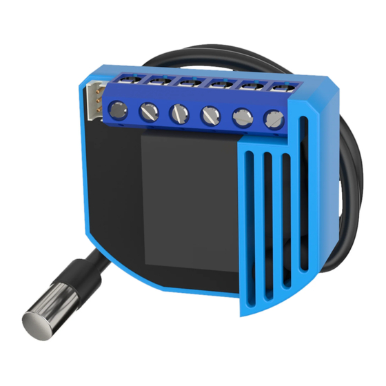
Qubino
The INNOVATIVE and SMALLEST
Flush heat & cool thermostat
ORDERING CODE
Z-WAVE FREQUENCY
ZMNHKA2
868,4 MHz
ZMNHKA3
921,4 MHz
ZMNHKA4
908,4 MHz
ZMNHKA5
869,0 MHz
ZMNHKA6
916,0 MHz
This Z-Wave module is used to regulate temperature in heating and
cooling mode. The module can be controlled either through Z-wave
network or through the wall switch.
The module is designed to be mounted inside a "flush mounting box"
and is hidden behind a traditional wall switch. Module measures power
consumption of connected device. It is designed to act as repeater in
order to improve range and stability of Z-wave network.
Supported switches
Module supports mono-stable switches (push button) and bi-stable
switches. The module is factory set to operate with bi-stable switches.
Installation
Before the installation disconnect power supply.
Connect the module according to electrical diagram.
Locate the antenna far from metal elements (as far as possible).
Do not shorten the antenna.
Danger of electrocution!
Module installation requires a great degree of skill and may be
performed only by a qualified and licensed electrician.
Even when the module is turned off, voltage may be present on its
terminals. Any works on configuration changes related to
connection mode or load must be always performed by
disconnected power supply (disable the fuse).
Note!
Do not connect the module to loads exceeding recommended values.
Connect the module only in accordance to the below diagrams.
Improper connections may be dangerous.
Package contents
Flush heat and cool thermostat module + Temperature sensor
Electrical diagram 230VAC
Notes for the diagram:
N
Neutral lead
L
Live lead
Q1
Output for Heating valve
Q2
Output for Cooling valve
I2
Input for switch (configurable) *
I1
Input for switch (configurable) *
TS
Terminal for digital temperature sensor (only for Flush heat
and cool thermostat module compatible digital temperature
sensor).
*
For details please check parameter 11 and 12 description
Electrical diagram 24VDC
Notes for the diagram:
N
+ VDC
L
- VDC
Q1
Output for Heating valve
Q2
Output for Cooling valve
I2
Input for switch (configurable) *
I1
Input for switch (configurable) *
TS
Terminal for digital temperature sensor (only for Flush
heat and cool thermostat module compatible digital
temperature sensor).
*
For details please check parameter 11 and 12 description
S
Service button (used to add or
remove module from the Z-Wave
network).
Durability of the module relay depends on applied load. For resistive
load (light bulbs, etc.) and 4A current consumption of each individual
electrical device, the durability exceeds 70.000 switches of each
individual electrical device.
Module Inclusion (Adding to Z-wave network)
Connect module to power supply (with temperature sensor
connected),
bring module within max. 1 meter (3 feet) of the main controller
enable add/remove mode on main controller
auto-inclusion (30 minutes after connected to power supply) or
press service button S for more than 2 second or
press push button I1 three times within 3s (3 times change switch
state within 3 seconds)
Module Exclusion/Reset (Removing from Z-Wave
network)
Connect module to power supply,
bring module within max. 1 meter (3 feet) of the main controller,
enable add/remove mode on main controller
press service button S for more than 6 second or
press push button I1 five times within 3s (5 times change switch
state within 3 seconds) in the first 60 seconds after the module is
connected to the power supply.
By this function all parameters of the module are set to default values
and own ID is deleted. If service button S is pressed more than 2 and
less than 6 second module is excluded, but configuration parameters
are not set to default values.
Association
Association enables Flush heat and cool thermostat module to transfer
commands inside Z-Wave network directly (without main controller) to
other Z-Wave modules.
Associated Groups:
Group 1: basic on/off (triggered at change of the output Q1 state and
reflecting its state) up to 16 nodes.
Group 2: basic on/off (triggered at change of the output Q2 state and
reflecting its state) up to 16 nodes.
Group 3: basic on/off (triggered at change of thermostat mode Off/Auto
and reflecting its state) up to 16 nodes.
Group 4: basic on/off (triggered by Too high temperature limit, it send FF)
up to 16 nodes.
Group 5: basic on/off (triggered by Too low temperature limit, it send FF)
up to 16 nodes.
Group 6: default reporting group (reserved for the main controller).
Configuration parameters
Parameter no. 1 – Input 1 switch type
Available configuration parameters (data type is 1 Byte DEC):
default value 1
0 mono-stable switch type (push button)
1 bi-stable switch type
Parameter no. 2 – Input 2 switch type
Available configuration parameters (data type is 1 Byte DEC):
default value 1
0 mono-stable switch type (push button)
1 bi-stable switch type
Parameter no. 3 – Input 1 contact type
Available configuration parameters (data type is 1 Byte DEC):
default value 0
0 NO (normally open) input type
1 NC (normally close) input type
Parameter no.4 – Input 2 contact type
Available configuration parameters (data type is 1 Byte DEC):
default value 0
0 NO (normally open) input type
1 NC (normally close) input type
Parameter no. 5 – Input 1 status on delay
Available configuration parameters (data type is 2 Byte DEC):
default value 0
1 – 32000 seconds
If the value of parameter is different to 0, means that the status of the
digital input (parameter 11 must be set to 2 – window sensor) will switch
to tripped after the inserted time has expired.
Parameter no. 6 – Input 1 status off delay
Available configuration parameters (data type is 2 Byte DEC):
default value 0
1 – 32000 seconds
If the value of parameter is different to 0, means that the status of the
digital input (parameter 11 must be set to 2 – window sensor) will switch
from tripped to untripped after the inserted time has expired.
Parameter no. 7 – Input 2 status on delay
Available configuration parameters (data type is 2 Byte DEC):
default value 0
1 – 32000 seconds
If the value of parameter is different to 0, means that the status of the
digital input (parameter 12 must be set to 2000 – condense sensor) will
switch to tripped after the inserted time has expired.
Parameter no.8 – Input 2 status off delay
Available configuration parameters (data type is 2 Byte DEC):
default value 0
1 – 32000 seconds
If the value of parameter is different to 0, means that the status of the
digital input (parameter 12 must be set to 2000 – condense sensor) will
switch from tripped to untripped after the inserted time (seconds) has
expired.
Parameter no. 10 - Activate / deactivate functions ALL ON/ALL OFF
Available configuration parameters (data type is 1 Byte DEC):
default value 255
255 - ALL ON active, ALL OFF active.
0 - ALL ON is not active ALL OFF is not active
1 - ALL ON is not active ALL OFF active
2 - ALL ON active ALL OFF is not active
Flush heat and cool thermostat module responds to commands ALL ON
/ ALL OFF that may be sent by the main controller or by other controller
belonging to the system.
Parameter no. 11- I1 Functionality selection
Available configuration parameters (data type is 2 Byte DEC):
default value 1
65535 – input I1 does not influence on the heat/ cool process
1 – input I1 changes the mode of the thermostat between Off and
Auto. In this case function on window sensor is disabled
2 – input I1 influences on cooling and heating valves according to
status of window sensor. In this case function of Off and Auto
selection by I1 is disabled
Parameter no. 12 – I2 Functionality selection
Available configuration parameters (data type is 2 Byte DEC):
default value 65535
65535 – input I2 does not influence on the heat/ cool process
From 0 to 990 – Temperature set point from 0.0 °C to 99.0 °C.
When I2 is pressed, it is automatically set temperature setpoint
according to value defined here. In this case function of condense
sensor is disabled
From 1001 to 1150 – Temperature set point from -0.1 °C to -15.0
°C
When I2 is pressed, it is automatically set temperature
setpoint according to value defined here. In this case function of
condense sensor is disabled
Advertisement

Subscribe to Our Youtube Channel
Related Manuals for QUBINO Flush

Summary of Contents for QUBINO Flush
- Page 1 1 – 32000 seconds Group 1: basic on/off (triggered at change of the output Q1 state and The module is designed to be mounted inside a “flush mounting box” reflecting its state) up to 16 nodes. If the value of parameter is different to 0, means that the status of the and is hidden behind a traditional wall switch.
- Page 2 (push) only when actual power in Watts in real time changes for Output circuit power of AC output The Flush heat & cool thermostat supports the following modes: Parameter no. 64 – Q1 Switch selection 2 X 920W (230VAC) ...
Need help?
Do you have a question about the Flush and is the answer not in the manual?
Questions and answers