Table of Contents
Advertisement
Advertisement
Table of Contents

Summary of Contents for Forbes Marshall Aquacon 4000
- Page 1 Instruction Manual Aquacon 4000 Conductivity Controller / Transmitter 01/2004...
- Page 2 Preface This manual serves to explain the use of the Aquacon 4000 Series. The manual functions in two ways, firstly as a step by step guide to help the user operate the instrument, and secondly as a handy reference guide. This instruction manual is written to cover as many anticipated applications of the Aquacon 4000 as possible.
- Page 3 Safety Information The Forbes Marshall Controller/ Transmitter shall be installed and operated only in the manner specified in the Instruction manual. Only skilled, trained or authorized person should carry out installation, setup and operation of the instrument. Before powering up the unit, make sure that power source it is connected to, is as specified in the top label.
-
Page 4: Table Of Contents
TABLE OF CONTENTS INTRODUCTION ............................1 ......................... 1 T THE VERY BEGINNING ............................1 NTENDED USE ..........................2 AFETY INTSRUCTIONS ..............2 UTTING OUT OF SERVICE ORRECT DISPOSAL OF THE UNIT PRODUCT DESCRIPTION.......................... 3 ..........................3 ESCRIPTION OF UNIT ....................4 EASUREMENT AND CONTROL SYSTEM ............................ - Page 5 10.1 ............................43 ARRANTY 10.2 ......................43 ACKAGING COPE OF DELIVERY 10.3 ..........................43 ETURN OF GOODS 10.4 ..................43 UIDELINES FOR RETURNING UNIT FOR REPAIR 10.5 ......................44 AINTENANCE AND LEANING APPENDICES ............................... 45 11.1 1 – U .................. 45 PPENDIX NIT FUSE AND JUMPER SETTINGS 11.2...
-
Page 6: Introduction
Aquacon 4000. If you have questions, which are not or insufficiently answered in this instruction manual, please contact your nearest office of Forbes Marshall Pvt. Ltd. Our engineers will be glad to assist you. Intended use Forbes Marshall Pvt. -
Page 7: Safety Intsructions
(see section 8). The Aquacon 4000 must not be repaired by the customer. The Aquacon 4000 must only be opened to replace the unit fuse or to set the jumper for Pt100/Pt1000 temperature sensor. This work must be carried out only by personnel familiar with the transmitter and who are qualified for such work. -
Page 8: Product Description
PRODUCT DESCRIPTION Description of unit The Forbes Marshall Aquacon 4000 is used for measuring conductivity and temperature values. The conductivity values can be measured using limit or P/PI control. The transmitter is available in two versions, one for panel mounting and one for wall mounting in a enclosure. -
Page 9: Measurement And Control System
• An appropriate measurement cable • An immersion, flow or process assembly • A final control element such as pump or valve • A chart recorder Aquacon 4000 Transmitter Chart Recorder 0/4 - 20 mA Power Mains (80 - 250 VAC) -
Page 10: Unit Overview
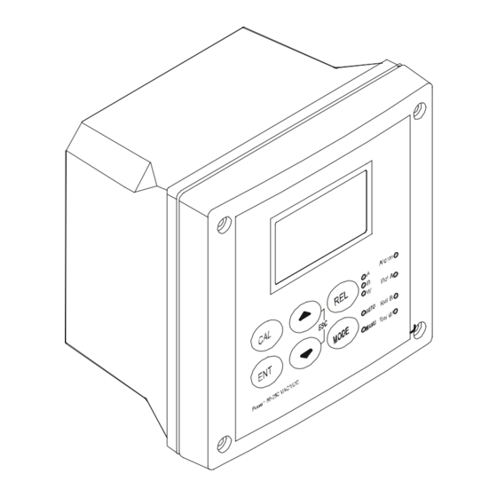
Instruction Manual Aquacon 4000 Unit overview Wall mounting version Panel mounting version... - Page 11 Instruction Manual Aquacon 4000...
-
Page 12: Display Overview
Instruction Manual Aquacon 4000 2.3.1 Display Overview The LC display shows two alpha-numerical fields for parameters and measured values as well as various mode and status indicators. Mode indicators: MEAS SETUP MEAS: measurement mode HOLD SETUP: Set-up mode µS CAL: Calibration mode Status indicator: °C °F... -
Page 13: Led Indicators
Instruction Manual Aquacon 4000 2.3.3 LED indicators Relay indicators If REL key is pressed the LED (A, B or W) indicates to which Relay (A, B or Wash) the displayed limit values refer. Relay mode indicators Auto LED lights if relay operation is set to automatic mode. Manu LED lights if relay operation is set to manual mode. -
Page 14: Menu Overview
Instruction Manual Aquacon 4000 2.3.5 Menu overview MEAS µS °C CCD “000” = Check calibration parameters (View only mode) ENTER CCD “11” = Calibration mode SCD “000” = Check setup parameters (View only mode) SCD “22” = Setup mode ENTER... - Page 15 Instruction Manual Aquacon 4000...
-
Page 16: Assembly And Installation
Instruction Manual Aquacon 4000 ASSEMBLY AND INSTALLATION Mounting the unit Wall mounting version 111.50 [4.39] 144 [5.67] 27.5 [1.08] For Pg13.5 cable glands 24 [.94] 39 [1.54] Pg13.5 (3 pcs.) 78 [3.07] 57.8[2.28] 80 [3.15] Holes for post mounting (4X) - Page 17 Instruction Manual Aquacon 4000 Panel mounting version Flat gasket 1mm [.04] (to be inserted by customer) Panel cut out UNIT: MM [INCH] Transmitter housing for panel mounting: protection class IP 54 (front), IP 40 (housing)
-
Page 18: Connection Diagram
Instruction Manual Aquacon 4000 Connection Diagram Caution: Ensure electrical mains are disconnected before proceeding. Connections for wall mounting version R ELA RELB WASH R ELAY A LAR M RELAY GND+12V PT10 0/ Curre nt Curre nt HOLD PT10 00 OP 2... - Page 19 Instruction Manual Aquacon 4000 When using 2 Cell type Conductivity electrode, terminal 15 should be shorted to terminal 16 and terminal 18 should be shorted to terminal 17. NOTE: a) Switch or circuit breaker shall included in the building installation.
- Page 20 Instruction Manual Aquacon 4000 Connections for panel mounting version AC mains live wire 2 Cell type Conductivity Input AC mains neutral wire 4 Cell type Conductivity Input AC mains protective earth wire 12V Power supply Relay A (SP 1) 12V ground...
- Page 21 Instruction Manual Aquacon 4000 NOTE: 1) Switch or circuit breaker shall included in the building installation. 2) It shall be in close proximity to the equipment and within easy reach of the operator. 3) It shall be marked as the disconnecting device for the equipment.
-
Page 22: Normal Operation
Instruction Manual Aquacon 4000 NORMAL OPERATION Measurement mode When the transmitter is powered on, the display first shows all segments briefly, after which the transmitter automatically enters into the Measurement mode. Please note: To guarantee accurate readings the measuring system (transmitter and sensor) must be calibrated. -
Page 23: Calibration Mode
Instruction Manual Aquacon 4000 CALIBRATION MODE You can access the Calibration mode directly from the Measurement mode by pressing the CAL key and entering the Calibration security code “11”. Calibration mode may also be accessed via the Setup mode (see section 6.1). -
Page 24: Calibration
Instruction Manual Aquacon 4000 Calibration This transmitter features a one-point calibration. Note: The calibration is always carried out in the specific range selected. MEAS SETUP µs µs HO LD HO LD HOLD HO LD HO LD °C °C AT C HOLD 1. -
Page 25: View Actual Cell Constant And Calibration Factor
Instruction Manual Aquacon 4000 Note: When calibrating with manual temperature compensation, the transmitter automatically changes from the preset process temperature to the calibration temperature. After leaving the Calibration mode, the transmitter switches back to the process temperature (for setting the calibration temperature and the process temperature, see section 6.3). -
Page 26: Setup Mode
Instruction Manual Aquacon 4000 SETUP MODE Enter Setup mode In the Setup mode the transmitter can be configured to your individual requirements. 1. While in Measurement mode press the ENT key. MEAS µS °C 2. The display prompts you to enter the security code. Set the security code with ▲... - Page 27 Instruction Manual Aquacon 4000...
-
Page 28: Temperature Compensation (Tc) Sub-Function
Instruction Manual Aquacon 4000 Temperature compensation (TC) sub-function This sub-function allows you to select the correct temperature compensation for optimum operations. SETUP SETUP SETUP SETUP HO LD HO LD HO LD HO LD °C SETUP HOLD 1. Select the “TC” sub-function, then press the ENT key. -
Page 29: Setting Temperature (Set °C°F) Sub-Function
Instruction Manual Aquacon 4000 Setting temperature (Set °C°F) sub-function SETUP SETUP SETUP SETUP SETUP HOLD HOLD HOLD HOLD HOLD °C SETUP SETUP SETUP HO LD HOLD HOLD °F °C 1. Select the “SET °C°F” sub-function, then press the ENT key. -
Page 30: Control Relaya / Relayb (Sp1/Sp2) Sub - Function
Instruction Manual Aquacon 4000 Control Relay A / Relay B (SP1/SP2) sub-function The SP1 sub-function determines the operating parameters for Relay A; while SP2 defines the operating parameters for Relay B. Since these groups have the same set-up parameters, they are described together. - Page 31 Instruction Manual Aquacon 4000 5. Setting the on-delay time lag: press the ▲ or ▼ key to enter the on-delay time for set point 1 (set point 2). The controller will delay activation of the relay for the number of seconds (0 to 2000 seconds) you select.
-
Page 32: Controller (Cntr) Sub-Function
Instruction Manual Aquacon 4000 Controller (CNTR) sub-function The CNTR sub-function determines the controller’s parameters. SETUP SETUP HO LD HO LD SETUP SETUP HOLD HO LD SETUP HO LD SETUP SETUP SETUP HOLD HO LD HO LD SETUP HO LD SETUP... - Page 33 Instruction Manual Aquacon 4000 1. Select the “CNTR” subfunction, then press the ENT key. 2. Selecting the controller type: press the ▲ or ▼ key to select the suitable controller type: − OFF = controller off Use control Off to operate controller as a monitor only or to prevent relays from switching.
- Page 34 Instruction Manual Aquacon 4000 − If the proportional controller type is set to pulse frequency control (PFC): 9. Selecting the relay status under Non-Alarm condition: press the ▲ or ▼ key to choose the desired relay status (de-energized = “DEEN” or energized = “EN”). Press the ENT key to confirm your selection.
-
Page 35: Current Output 1 Sub-Function
Instruction Manual Aquacon 4000 Current Output 1 sub-function In this subfunction you set the current output range of the transmitter for conductivity values. SETUP SETUP SETUP SETUP SETUP HO LD HOLD µS HOLD µS HOLD HOLD SETUP SETUP SETUP SETUP... -
Page 36: Current Output 2 Sub-Function
Instruction Manual Aquacon 4000 Current Output 2 sub-function In this sub-function you set the current output range of the transmitter for temperature values. SETUP SETUP SETUP SETUP HO LD HOLD HOLD HOLD °C °C SETUP SETUP SETUP HOLD HOLD HOLD °C... -
Page 37: Wash Relay (Wash) Sub-Function
Instruction Manual Aquacon 4000 Wash relay (WASH) sub-function In this sub-function you set the parameters for the wash relay. SETUP SETUP SETUP SETUP SETUP HO LD HO LD HO LD HO LD HOLD SETUP SETUP HOLD HO LD 1. Select the “WASH” sub-function, then press the ENT key. -
Page 38: Measuring Range Selection (Rang) Sub-Function
Instruction Manual Aquacon 4000 Measuring range selection (RANG) sub-function In this sub-function you select the measuring SETUP SETUP range. HOLD HO LD µS SETUP HO LD µS SETUP HOLD µS SETUP HOLD µS SETUP HOLD SETUP HO LD 1. Select the “RANG” sub-function, then press the ENT key. -
Page 39: Configuration (Cnfg) Sub-Function
Instruction Manual Aquacon 4000 6.10 Configuration (CNFG) sub-function In this sub-function you configure the transmitter to suit your requirements. SETUP SETUP SETUP SETUP SETUP HO LD HO LD HO LD HO LD HOLD SETUP SETUP HOLD HO LD SETUP SETUP... -
Page 40: Calibration (Cal) Sub-Function
Instruction Manual Aquacon 4000 6. Selecting the alarm contact type: press the ▲ or ▼ key to select the alarm contact type: − “STDY” = steady contact − “FLET” = fleeting (single pulse) contact Press the ENT key to confirm your selection. -
Page 41: Relay Modes
Instruction Manual Aquacon 4000 RELAY MODES You can control devices connected to Relay A, Relay B or wash relay via the front panel of the transmitter. In Automatic mode, the transmitter’s set point values activate the relays. In Manual mode, you can manually turn “on” and “off” the control devices connected to the relays. -
Page 42: Manual Relay Mode
Instruction Manual Aquacon 4000 Manual relay mode In manual relay mode, you can manually turn “on” and “off” the control devices connected to Relay A, Relay B or Wash relay. 1. While in Measurement mode press the MODE key. 2. The display prompts you to enter the security code. Press the ▲ or ▼ key to set security code to “22”. -
Page 43: Technical Specifications
Instruction Manual Aquacon 4000 TECHNICAL SPECIFICATIONS General specifications Conductivity Measuring range No Measuring range Resolution 0.000 - 2.000 µS/cm 0.001 µS/cm 0.00 - 20.00 µS/cm 0.01 µS/cm 0.0 - 200.0 µS/cm 0.1 µS/cm 0- 2000 µS/cm 1 µS/cm 0.00 - 20.00 mS/cm 0.01 mS/cm... -
Page 44: Specifications For Wall Mount Version
Instruction Manual Aquacon 4000 Alarm Functions Function (switchable) Latching / pulse Pickup delay 0 to 2000 seconds Switching voltage Max. 250 VAC Switching current Max. 3A Switching power Max. 600 VA Display UV coat, backlit 14 segments display with symbols for... - Page 45 Instruction Manual Aquacon 4000...
-
Page 46: Specifications For Panel Mount Version
Instruction Manual Aquacon 4000 Mechanical Specifications Dimensions 144 x 144 x 111.5 mm (5.67 x 5.67 x 4.39 inch) Weight 950 g Material Insulation NEMA 4X, IP 65 Specifications for panel mount version Electrical Data and Connections Signal Output Two 0/4 to 20 mA outputs for conductivity and temperature, galvanically isolated. -
Page 47: Accessories
Instruction Manual Aquacon 4000 ACCESSORIES Replacement Unit Product Description Forbes Marshall Order Code Aquacon 4000 Aquacon 4000W Controller / Transmitter, wall mount version Aquacon 4000 Aquacon 4000P Controller / Transmitter, panel mount version... -
Page 48: General Information
Before returning goods for any reason whatsoever, Customer Service Dept. have to be informed in advanced. Items must be carefully packed to prevent damage during shipment, and insured against possible damage or loss. Forbes Marshall will not be responsible for any damage resulting from careless or insufficient packing. -
Page 49: Maintenance And Cleaning
10.5 Maintenance and Cleaning Maintenance The Aquacon 4000 contains no user repairable components. Please contact Forbes Marshall if there is any problems with the unit. Cleaning To remove dust, dirt and spots, the external surfaces of the transmitter may be wiped with a... -
Page 50: Appendices
Instruction Manual Aquacon 4000 APPENDICES 11.1 Appendix 1 – Unit fuse and jumper settings Caution! Before opening the unit to replace the unit fuse or to set the jumper for Pt 100 / Pt 1000 temperature sensor, make sure the mains cable is separated from the power supply. - Page 51 Instruction Manual Aquacon 4000 Panel mounting version (view from top)
-
Page 52: Appendix 2 - Conductivity Of Various Aqueous Solutions At 25 °C / 77 °F
Instruction Manual Aquacon 4000 11.2 Appendix 2 – Conductivity of various aqueous solutions at 25 °C / 77 °F Conductivity Resistivity Ultra-pure Water 0.055 µS/cm 18.18 MΩ-cm Power Plant Boiler Water 0.05 - 1 µS/cm 1 - 18 MΩ-cm Distilled Water 0.5 µS/cm... -
Page 53: Appendix 3 - Simple Explanation On The Function Of Hysteresis
Instruction Manual Aquacon 4000 11.3 Appendix 3 – Simple explanation on the function of hysteresis SP1 Set to LO SP2 Set to HI RELAY ON RELAY OFF 1880 1900 µS FORWARD DIRECTION HYSTERESIS BAND REVERSE DIRECTION The controller relay activates when the set-point is reached. In the reverse direction, it does not de-activate when the value reaches the set-point. -
Page 54: Appendix 4 - General Instructions Concerning Controller Setting
Instruction Manual Aquacon 4000 11.4 Appendix 4 – General instructions concerning Controller Setting 11.4.1 Control characteristic of Controllers used as limit value switch MIN function MAX function 100% SP 1 SP 2 Xp = 0 Xp = 0 11.4.2 Control characteristic of P-Controllers as proportional controller... -
Page 55: Control Signal Of Pulse Length Controllers
Instruction Manual Aquacon 4000 11.4.4 Control signal of Pulse length Controllers Relay Pulse Length T tOFF Time [s] The output relay of the pulse length controller is clock-timed. The switching period T remains constant. Depending on the divergence from the limit value, the switch on time tON is increased or decreased in accordance with the proportional range Xp. -
Page 56: Control Signal Of Pulse Frequency Controllers
Instruction Manual Aquacon 4000 11.4.5 Control signal of Pulse Frequency Controllers Relay Pulse Length T tOFF Time [s] The output relay of the pulse frequency controller is clock-timed. The pulse duration tON remains constant at 250 msec. Depending on the divergence from the limit value, the frequency (1/T) is increased or decreased in accordance with the proportional range Xp. -
Page 57: Appendix 5 - Abbreviations Used In Menu Displays
Instruction Manual Aquacon 4000 11.5 Appendix 5 – Abbreviations used in menu displays Abbreviation Meaning Abbreviation Meaning MEAS Measurement Relay Calibration Proportional band Enter T. PL Pulse length time C. CD Calibration security code F. PF Pulse frequency S. CD... - Page 59 For more information on Forbes Marshall products, visit our website listed below: Forbes Marshall Pvt. Ltd. Distributed by: A-34/35 MIDC Estate, ‘H’ Block, Pimpri, Pune 411 018. India. Tel: 91 (0) 20 27442020 Fax: 91 (0) 20 27442040 E-mail: analsales@forbesmarshall.com Web-site: www.forbesmarshall.com...
Need help?
Do you have a question about the Aquacon 4000 and is the answer not in the manual?
Questions and answers