Table of Contents
Advertisement
Advertisement
Table of Contents

Related Manuals for KUHN RPB

Summary of Contents for KUHN RPB
- Page 1 Complementary instructions GC003AGB D Control box - English - 08-2010 GC003AGB D...
-
Page 3: Dear Owner
Control box $Dear Owner In buying a Kuhn machine you have chosen wisely. Into it have gone years of thought, research and improvement. You will find, as have thousands of owners all over the world, that you have the best that engineering skill and actual field testing can produce. -
Page 4: Table Of Contents
Control box $Contents Dear Owner ........................1 Contents..........................2 Control box identification....................4 Front view............................4 Manufacturers' marking ........................5 Optional equipment..........................6 Safety..........................7 Description of symbols used in this document................7 Safety instructions ...........................8 General description......................10 Description and glossary.......................10 Technical specifications ........................11 Description of control elements....................12 Access and menu navigation ......................14 Menu tree structure ........................16 Assembly and fitting ....................17... - Page 5 Control box Configuration ....................... 20 Adjustments before first use......................21 Preliminary adjustments at work ....................24 Machine use ......................... 40 Tank ..............................40 Operating data ..........................42 Spraying start ..........................43 Information............................46 Unfolding/folding of the boom arms .................... 47 Application rate adjustment ......................
-
Page 6: Control Box Identification
Control box $Control box identification 1. Front view Control box identification... -
Page 7: Manufacturers' Marking
Control box 2. Manufacturers' marking Please note the serial number of your equipment. This information is to be indicated to the dealer for all spare parts orders. - Serial no. (1): When switched on, the control box displays the following information: - Control box version (1): Control box identification... -
Page 8: Optional Equipment
See machine corresponding to a specific configuration. Check with your authorized KUHN dealer the equipment compatibility with your machine. Prior to using optional equipment, it is necessary to define the parameters. See concerned section in the "Configuration"... -
Page 9: Safety
Control box $Safety 1. Description of symbols used in this document This symbol indicates a potentially hazardous situation that if not avoided, could result in serious bodily injury. This symbol is used to identify special instructions or procedures which, if not followed strictly, could result in machinery damage. -
Page 10: Safety Instructions
Never let anyone operate the machine who is not trained to do so. Should you have any difficulties in understanding certain parts in this manual, please contact your KUHN dealer. Precautions to take before using the control box Place the control box so that it cannot interfere with other tractor controls and be activated inadvertently. - Page 11 Control box Precautions to take when using the control Do not operate the control box while a person is carrying out work on the machine. Switch off control box before carrying out any maintenance or repair work on the machine. Precautions when driving Before transporting the machine on public roads, make sure no function of the control box or of the control...
-
Page 12: General Description
Control box $General description 1. Description and glossary Machine wiring harness 5-pin connector Control box mounting Keyboard with 8 function buttons and 1 On/Off button Screen Spraying opening and shut-off switches General description... -
Page 13: Technical Specifications
Control box 2. Technical specifications Dimensions: Length 125 mm (4.9 ’’) Width 110 mm (4.3 ’’) Depth 95 mm (3.7 ’’) Operating temperature from -20°C à +60°C Storage temperature up to +85°C Voltage input 12 V Screen 120x 64 pixels Connector Machine wiring harness 5-pin connector Wiring harness... -
Page 14: Description Of Control Elements
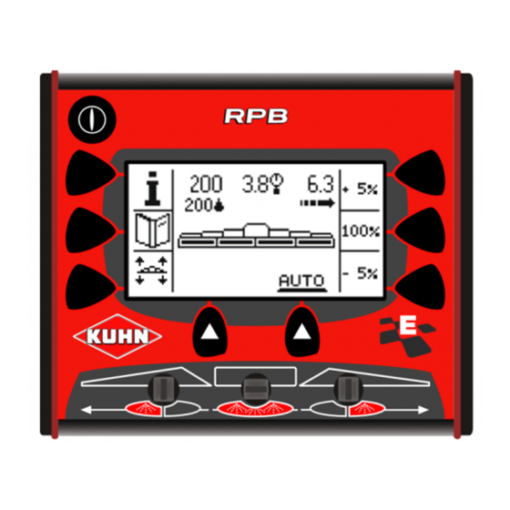
Control box 3. Description of control elements Description of the controls Start/Stop: Control box Screen Selection key Switch: Left sequential opening/closing of the spraying sections Switch: Main opening/closing of the spraying sections Switch: Right sequential opening/closing of the spraying sections General description... - Page 15 Control box Description of screen zones Menu and data display Selection key display Work screen description Programmed application rate Measured application rate Pressure Spraying sections Groundspeed General description...
-
Page 16: Access And Menu Navigation
To navigate in the menus,use the following keys: - Menu line change key (1). - Selection validation key (2). - Key to return to the previous menu (3). Menu display (1). The RPB control box features circular menus. General description... - Page 17 Control box Entry and modification of a value - Press keys (1) and (2) to select the parameter to modify: • Move the cursor upwards (1). • Move the cursor downwards (2). - Press key (3) to modify parameter. Numerical value: - Press keys (1) or (2) to modify the value: •...
-
Page 18: Menu Tree Structure
Control box 5. Menu tree structure Terminal Main menu Settings Alarms Nozzles Sprayer Optional equipment Tank Wheels Circulation Booms General description... -
Page 19: Assembly And Fitting
Control box $Assembly and fitting 1. Tractor requirements The tractor must supply a voltage comprised between 11 V and 14 V. 2. Description of the connection Never connect battery charger or perform welding tasks without having previously disconnected the control box. - Connect the machine 3-pin power plug (1). -
Page 20: Positioning And Parking
Control box 3. Positioning and parking The control box must be easily accessible from the tractor cab. The control box must be fitted in a dry place, safe from bad weather. Control box mounting The control box is placed in the tractor cabin on support (1) to mount. -
Page 21: Putting Into Service
- Press key (1) for 2 seconds to switch the control box off. 2. Standby mode The control box RPB switches to the standby mode when not used for a few minutes. - Press on a key to exit the standby mode. -
Page 22: Configuration
Control box $Configuration The configuration modification must be made by your KUHN authorized dealer. Main menu Settings Starting from the main menu: - Press key (1) to access the "Settings" menu. - Press key (1) to enter the password. Password: 7 - Press 7 time on key (1). -
Page 23: Adjustments Before First Use
Control box 1. Adjustments before first use Main menu Configuration Terminal As from the "Configuration" menu: - Press key (1) to access the "Terminal" menu. - Press on the button (2). Setting the language - Press key (1) to access the menu. - Press key (2) to change the language. - Page 24 Control box Setting contrast - Press key (1) to access the menu. - Press key (2) to modify the contrast. Setting back-lighting - Press key (1) to access the menu. - Press key (2) to switch from one mode to the other. No: White text on black background.
- Page 25 Control box System - Press key (1) to access the menu. - Press on the button (2). Speed simulator: The stimulator allows stationary spraying. - Press key (1) to modify parameter. Yes: Activated. No: Deactivated. When starting to move, the speed simulator is automatically deactivated.
-
Page 26: Preliminary Adjustments At Work
Control box 2. Preliminary adjustments at work Main menu Configuration Sprayer As from the "Configuration" menu: - Press key (1) to access "Sprayer" menu. - Press on the button (2). Wheel - Press on the button (1). The control box can save up to 5 different configurations. All configurations are factory preset. - Page 27 Control box Modifying a configuration: - Press key (1) to access the parameters to modify. Type: - Press key (2) to modify parameter. Number of pulses: - Press key (2) to modify parameter. Automatic calibration: When used for the first time, the equipment must be calibrated.
- Page 28 Control box Boom - Press on the button (1). The control box can save up to 5 different configurations. All configurations are factory preset. All configurations can be modified. Activate / deactivate a configuration: - Press key (1) to select a configuration. - Press key (2) to switch from one mode to the other.
- Page 29 Control box Spraying flowmeter When used for the first time, the equipment must be calibrated. Manual calibration: - Note the flowmeter coefficient (1) = A. - Switch to stationary spraying mode. - Go to manual mode. - Adjust pressure to 3 bars (44 psi). - Place a test tube underneath the nozzle.
- Page 30 Control box Circulation - Press on the button (1). Activate / deactivate a configuration: - Press key (1) to select a configuration. - 2-way standard circulation (N2). - 3-way standard circulation (N3). Refer to the machine operator's manual. - Press key (2) to switch from one mode to the other. No: Configuration deactivated.
- Page 31 Control box Tank - Press on the button (1). Body capacity: - Press key (1) to modify parameter. Density: - Press on the button (1). - Press key (1) to access the parameters to modify. - Press key (2) to modify parameter. Configuration...
- Page 32 Control box Regulation - Press on the button (1). - Press key (1) to access the parameters to modify. Pump coefficient: This parameter allows filtering the pump flow variations. The more the pump flow is varies, the more the coefficient must be high. The more the pump flow is stable, the more the coefficient must be low.
- Page 33 Control box Application rate adjustment: This parameter allows defining the application rate adjustment rate: • 5% or 10% or 15% or 20% or 25%. - Press key (2) to modify parameter. Management of the minimum pressure: Press key (2) to modify parameter. No: During work at low speed, the application rate adjustment is obtained by reducing the pressure.
- Page 34 Control box Nozzles - Press on the button (1). Always calibrate the nozzles using water. The control box can save up to 5 different configurations. All configurations are factory preset. All configurations can be modified. Activate / deactivate a configuration: - Press key (1) to select a configuration.
- Page 35 Control box Pressure sensor - Press key (1) to switch from one mode to the other. No: Sensor off. Yes: Sensor on. - Press on the button (2). We recommend not to modify the initial setting. Automatic calibration: The machine is calibrated at the factory. For models fitted with a DPI control box: - Turn off control box DPI.
- Page 36 Control box Hydraulics - Press key (1) to switch from one mode to the other. No: For models without 3-function electro- hydraulic valve For models fitted with a solenoid valve block. Yes: For models fitted with a 3-function electro- hydraulic selector. For models fitted with a solenoid valve block: The machine is fitted with a CH10 control box that groups the hydraulic functions.
- Page 37 Control box Alarms - Press on the button (1). Flow alarm This alarm indicates that the preset flow setting is not reached. - Press key (1) to switch from one mode to the other. No: Alarm deactivated. Beep: Alarm activated. Low noise. Buzzer: Alarm activated.
- Page 38 Control box Pressure alarm The alarm indicates the pressure is below/over the set limit. Refer to the nozzle configuration. - Press key (1) to switch from one mode to the other. No: Alarm deactivated. Beep: Alarm activated. Low noise. Buzzer: Alarm activated. Loud noise. - Press on the button (2).
- Page 39 Control box Tank low level prewarning alarm The alarm indicates that the tank level is below the set limit. - Press key (1) to switch from one mode to the other. No: Alarm deactivated. Beep: Alarm activated. Low noise. Buzzer: Alarm activated. Loud noise. - Press on the button (2).
- Page 40 Control box Tank low level alarm The alarm indicates that the tank level is below the set limit. - Press key (1) to switch from one mode to the other. No: Alarm deactivated. Beep: Alarm activated. Low noise. Buzzer: Alarm activated. Loud noise. - Press on the button (2).
- Page 41 Control box Optional equipment Do not activate optional equipment that is not installed. - Press on the button (1). Flashing light - Press key (1) to switch from one mode to the other. No: Equipment not installed. Yes: Equipment installed. Working headlights - Press key (1) to switch from one mode to the other.
-
Page 42: Machine Use
Control box $Machine use Refer to the machine operator's manual. 1. Tank Main menu Tank Starting from the main menu: - Press key (1) to access "Tank" menu. The control box displays the following information: - Tank rest. Density - Press key (1) to switch from one mode to the other. Machine use... - Page 43 Control box Filling - Fill the tank. - Press key (1) to modify parameter. Full filling: - Press on the button (1). Partial filling: - Pres on keys (2) and (3) to adjust the value. - Press the button (4) to confirm. Machine use...
-
Page 44: Operating Data
Control box 2. Operating data Main menu Operating data Starting from the main menu: - Press key (1) to access "Counters" menu. - Press on the button (2). The control box displays the following information: - Partial volume. - Partial area. - Partial distance. -
Page 45: Spraying Start
Control box 3. Spraying start Main menu Spraying start Starting from the main menu: - Press key (1) to access the "Spraying start" menu. - Press on the button (2). According to the configuration, the choices offered are different: - If several configurations are activated, the control box offers a list of choices. - Page 46 Control box Wheel: - Press key (1) to select a configuration. - Press the button (2) to confirm. Boom: - Press key (1) to select a configuration. - Press the button (2) to confirm. Circulation: - Press key (1) to select a configuration. - Press the button (2) to confirm.
- Page 47 Control box Operating data: - Press key (1) to select the counter. - Press key (2) to modify parameter. - Press key (1) for counter reset. Press key (1) during 3 seconds to reset the counters. - Press the button (2) to confirm. The control box displays the work screen.
-
Page 48: Information
Control box 4. Information To display the information screen: - Press on the button (1). The control box displays the following information: • Flow. • Partial area. • The number of litres spread. • Tank rest. The control box automatically redisplays the work screen after 10 seconds. -
Page 49: Unfolding/Folding Of The Boom Arms
Control box 5. Unfolding/folding of the boom arms Check that nobody is within the machine pivoting area. If there is someone, make sure the person moves away. If a speed exceeding 4 km/h is detected, the control box switches into the slope corrector mode. - Page 50 Control box Unfold the booms: Unfold the central arms: - Press on the button (1). - Shift the tractor hydraulic valve. Unfold the outer arms: - Press on the button (1). - Shift the tractor hydraulic valve. - Press on the button (1). The boom is unfolded.
-
Page 51: Application Rate Adjustment
Control box 6. Application rate adjustment To adjust the application rate adjustment rate, see concerned section in the "Configuration" section. - Press key (1) to increase the programmed application rate. - Press key (2) to reduce the programmed application rate. To revert to the initial application rate, press key (1). -
Page 52: Auto/Man Mode
Control box 7. AUTO/MAN mode - Press key (1) to switch from one mode to the other. Automatic mode: - The control box opens/closes the flow regulation valve to maintain the programmed application rate. Manual mode: - Press keys (1) and (2) to open / shut the flow regulation valve and adjust the spraying pressure. -
Page 53: Opening/Shut-Off Of The Spraying Sections
Control box 8. Opening/shut-off of the spraying sections Switch (1): Left sequential opening/closing of the spraying sections. Switch (2): Main opening/closing of the spraying sections. Switch (3): Right sequential opening/closing of the spraying sections. Display a: Spraying open. Spraying section open. - Page 54 Control box Main opening/closing of the spraying sections Main opening of the spraying sections: - Operate and maintain switch (1) downwards during 2 seconds. Main shut-off of the spraying sections: - Operate and maintain switch (1) upwards during 2 seconds. Machine use...
- Page 55 Control box Sequential opening/closing of the spraying sections Left sequential opening of the spraying sections: - Operate switch (1) to the right. - Repeat procedure for each section. Left sequential shutting of the spraying sections: - Operate switch (1) to the right. - Repeat procedure for each section.
- Page 56 Control box Right sequential opening of the spraying sections: - Operate switch (1) to the left. - Repeat procedure for each section. Right sequential shutting of the spraying sections: - Operate switch (1) to the left. - Repeat procedure for each section. Machine use...
- Page 57 Control box Partial opening / shutting of the spraying sections Section preselection to the right: - Operate and maintain switch (1) to the left during 2 seconds. Open the section: - Operate switch (1) to the left. Shut-off the section: - Operate switch (1) to the left.
- Page 58 Control box Section preselection to the left: - Operate and maintain switch (1) to the right during 2 seconds. Open the section: - Operate switch (1) to the right. Shut-off the section: - Operate switch (1) to the right. Machine use...
-
Page 59: Menu" Key
Control box 9. "Menu" key To display the "Menu" screen: - Press on the button (1). Tank The control box displays the following information: - Tank rest. Density - Press key (1) to switch from one mode to the other. Filling - Fill the tank. - Page 60 Control box Full filling: - Press on the button (1). Partial filling: - Pres on keys (2) and (3) to adjust the value. - Press the button (4) to confirm. Work end - Press on the button (1). Machine use...
-
Page 61: Optional Equipment
Control box $Optional equipment 1. Work spotlights and flashing light The work spotlights and flashing light can be switched on simultaneously. Working headlights - Press key (1) to switch from one mode to the other. Display a: Work lights off. Display b: Work lights on. -
Page 62: Maintenance And Storage
The control box does not require any particular maintenance, in the case of a breakdown or a malfunction call your KUHN technician. 2. Storage At the end of each season - Store control box in a dry place free of dust. -
Page 63: Trouble Shooting Guide
Verify speed sensor and wiring function. Faulty sensor. Immediately replace worn or damaged parts with genuine The speed is incorrect. KUHN parts. Carry out the calibration. Incorrect sensor adjustment. See concerned section in the "Configuration" chapter. See concerned section in the "Configuration"... -
Page 64: Alarms
Control box 1. Alarms To configurate the alarms, see section in the "Settings" chapter. If several alarms are activated simultaneously, the alarm messages are displayed successively. Flow alarm This alarm indicates that the preset flow setting is not reached. Maximum flow alarm The control box displays an alarm message. - Page 65 Control box Pressure alarm The alarm indicates the pressure is below/over the set limit. Maximum pressure alarm The control box displays an alarm message. 2 "beeps" sound. Remedy: - Check the type of nozzle. Replace if necessary. - Reduce ground speed. Minimum pressure alarm The control box displays an alarm message.
-
Page 66: Diagnosis
Control box 2. Diagnosis Main menu Configuration Terminal Diagnosis As from the "Terminal" menu: - Press key (1) to access the "Diagnosis" menu. - Press on the button (2). As from any screen: - Simultaneously press keys approximately 3 seconds. The diagnosis menu enables controlling the machine's electric system (Battery voltage, Sensors...). -
Page 67: Description Of Fuses
Control box 3. Description of fuses Prior to any maintenance or repair on the junction box, disconnect the machine and tractor power supply. Never replace damaged fuse by a fuse of higher value. Keep fuses safe from rain and humidity. The cards are made up of 4 tie-point blocks: - (1) Signalling. - Page 68 Control box Housing: Powered valves Outputs: Gy H: Relay control. Gy M: +12V Flashing light. 1H: Filling stop valve - 1M: Filling stop valve + 2H: Main stop valve - 2M: Main stop valve + 3H: Flow regulation valve - 3M: Flow regulation valve + 4H: Section valve 1 - 4M: Section valve 1 +...
- Page 69 Control box Sensors: 1M: Signal frequency: Wheel. 2M: Signal frequency: Flowmeter. 3M: Signal frequency: Return flowmeter. 4M: Signal frequency: Filling flowmeter. 5M: Analog signal: Pressure sensor. 6M: Analog signal: Electronic gauge. 7M: Reserved. 8M: Reserved. From 1H to 8H: +12V. From 1B to 8B: Ground.
- Page 70 Control box Housing: Solenoid valve block Outputs: Gy H: Relay control. Gy M: +12V Flashing light. 1H: Reserved. 1M: Reserved. 2H: Reserved. 2M: Reserved. 3H: On / Off. 3M: Automatic / Manual. 4H: Left outer arm opening. 4M: Left outer arm closing. 5H: Opening central arms.
- Page 71 Control box Sensors: 1M: Signal frequency: Wheel. 2M: Analog signal: Gauge. 3M: Analog signal: Follower axle/Self-steering axle: Front. 4M: Analog signal: Follower axle/Self-steering axle: Rear. 5M: Reserved. 6M: Analog signal: Height. 7M: Reserved. 8M: Signal frequency: Reverse. From 1H to 8H: +12V. From 1B to 8B: Ground.
-
Page 72: Factory Counters
Control box 4. Factory counters Main menu Configuration Terminal Operating data As from the "Terminal" menu: - Press key (1) to access "Counters" menu. - Press on the button (2). The control box displays the following information: - Total area. - Total volume. -
Page 73: Version
Control box 5. Version Main menu Configuration Terminal Version As from the "Terminal" menu: - Press key (1) to access the "Version" menu. The control box displays the following information: - Control box version. Trouble shooting guide... -
Page 74: Appendix
Control box $Appendix 1. Configuration Wheels Factory settings User settings Wheel 1 Status Type 9.5 x 48 Number of pulses Wheel 2 Status Type 12.4 x 46 Number of pulses Wheel 3 Status Type 11.2 x 48 Number of pulses Wheel 4 Status Type... - Page 75 Control box Booms Factory settings User settings Boom 1 Status Name Boom 1 Width 0.5 m (1’8’’) Number of nozzles section 1 Number of nozzles section 2 Number of nozzles section 3 Number of nozzles section 4 Number of nozzles section 5 Number of nozzles section 6 Number of nozzles section 7 Factory settings...
- Page 76 Control box Factory settings User settings Boom 3 Status Name Boom 3 Width 1.0 m (3’3’’) Number of nozzles section 1 Number of nozzles section 2 Number of nozzles section 3 Number of nozzles section 4 Number of nozzles section 5 Number of nozzles section 6 Number of nozzles section 7 Factory settings...
- Page 77 Control box Factory settings User settings Boom 5 Status Name Boom 5 Width 5.0 m (16’5’’) Number of nozzles section 1 Number of nozzles section 2 Number of nozzles section 3 Number of nozzles section 4 Number of nozzles section 5 Number of nozzles section 6 Number of nozzles section 7 Spraying flowmeter...
- Page 78 Control box Tank Factory settings User settings Capacity 1000 L (264 US gal) Density Nitrogen 1.30 Others 1.15 Regulation Factory settings User settings Pump coefficient Regulation coefficient Application rate adjustment Management of the minimum pressure Valve opening time Nozzles Factory settings User settings Nozzle 1 Status...
- Page 79 Control box Factory settings User settings Nozzle 2 Status Name Green Flow to 3 bar (43.5 psi) 0.6 L/min (0.16 US gal/min Maximum pressure 7 bar (102 psi) MINIMUM operating pressure 1.5 bar (22 psi) Nozzle 3 Status Name Yellow Flow to 3 bar (43.5 psi) 0.8 L/min (0.21 US gal/min...
- Page 80 Control box Pressure sensor Factory settings User settings Status Pressure display Factory settings User settings Status Hydraulic functions Factory settings User settings Status Appendix...
- Page 81 Control box Alarms Factory settings User settings Flow alarm Status Beep Trip Pressure alarm Status Beep Trip Tank low level prewarning alarm Status Beep Trip 0 L (0 US gal) Tank low level alarm Status Beep Trip 0 L (0 US gal) Optional equipment Factory settings User settings...
-
Page 82: Limited Warranty
Control box $Limited warranty Limited warranty... - Page 83 Control box Limited warranty...
Need help?
Do you have a question about the RPB and is the answer not in the manual?
Questions and answers