Table of Contents
Advertisement
Advertisement
Table of Contents

Summary of Contents for Strand Lighting 63022VN
- Page 2 Information contained in this document may not be duplicated in full or in part by any person without prior written approval of Strand Lighting Inc. Its sole purpose is to provide the user with conceptual information on the equipment mentioned. The use of this document for all other purposes is specifically prohibited.
-
Page 3: Table Of Contents
Vision Net Pushbutton Station Installation & Operation Guide TABLE OF CONTENTS Overview ........................... 2 Vision Net System Overview .................... 2 Quick Start ........................2 8-Button Remote Station Overview .................. 2 Specifications ..........................3 Installation ..........................4 Installation Steps ....................... 4 Vision Net Station Operation Modes .................. -
Page 4: Overview
Screens, the system provides remote access to scenes, Master Raise/Lower control, Multi- room partition control, or Master Station Lockout. Vision Net Stations are compatible with Strand Lighting A21, R21, C21 and EC21 Dimming Cabinets. Vision Net products are controlled by the Vision Net System protocol. All Vision Net control devices must be connected to the Vision Net system and given a unique ID (or address) in order to interact properly. -
Page 5: Specifications
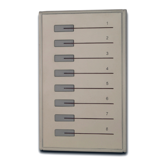
Vision Net Pushbutton Station Installation & Operation Guide 8-Button Remote Station Overview The Vision Net Button Remote Stations (63021VN, 63022VN, 63024VN & 63028VN) are used in combination with other Vision Net panels to provide quick, one-touch access to up to 8 Preset Scenes. -
Page 6: Installation
Vision Net Pushbutton Station Installation & Operation Guide INSTALLATION The Vision Net Network consists of a single CAT5e cable connecting all modules in a daisy chain manner. All units connect to the network using a 9-pin plug-in connector (included). Installation Steps Step 1. -
Page 7: Vision Net Station Operation Modes
1 by the factory and will need to be set to the required address and programmed as required for your installation. Vision Net stations are programmed and have their ID’s set using the Vision.Net Designer software (supplied separately, part number #67518). To obtain the Vision.Net Designer software, please contact your local Strand Lighting Distributor. - Page 8 Network via the Vision Net RS232 station, using an RS232 lead. Alternatively you can connect to the Vision Net network using a Bluetooth interface. Please contact your local Strand Lighting Office for more details on this interface. Step 2. Set Vision Net Designer to work "On Line."...
- Page 9 Network via the Vision Net RS232 station, using an RS232 lead. Alternatively you can connect to the Vision Net network using a Bluetooth interface. Please contact your local Strand Lighting Office for more details on this interface. Step 2. Set Vision Net Designer to work "On Line."...
- Page 10 Network via the Vision Net RS232 station, using an RS232 lead. Alternatively you can connect to the Vision Net network using a Bluetooth interface. Please contact your local Strand Lighting Office for more details on this interface. Step 2. Set Vision Net Designer to work "On Line."...
-
Page 11: Operation
Network via the Vision Net RS232 station, using an RS232 lead. Alternatively you can connect to the Vision Net network using a Bluetooth interface. Please contact your local Strand Lighting Office for more details on this interface. Step 2. Set Vision Net Designer to work "On Line."...
Need help?
Do you have a question about the 63022VN and is the answer not in the manual?
Questions and answers