
Related Manuals for Dillenger CONVERSION KIT

Summary of Contents for Dillenger CONVERSION KIT
- Page 1 CONVERSION KIT User Manual Dillenger Premium Off Road Kit - Samsung Powered English Please read through carefully before beginning your conversion...
-
Page 2: Thank You
THANK YOU Thank you for purchasing your new Dillenger conversion kit! We know you’ll love it, and with some care it should last for a very long time. Please read through this manual carefully before operating the kit. SAFETY Mechanical Safety Check: Routinely check the condition of your bike. -
Page 3: Table Of Contents
Contents Thank You Safety Item Check List Install Overview Installation Process Installation instructions Cassette and Disk Brake Install Wheel Install Battery Cradle Install Battery Install Handlebar Controls Install Display Install Thumb Throttle Install E-Brake Sensors Install Removable Pedal Assist Sensor (RPAS) Install Wiring Install Tidy Up Battery Operation... -
Page 4: Item Check List
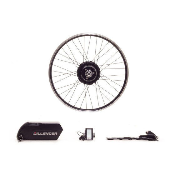
ITEM CHECK LIST Each conversion kit is tested for quality control before shipping to a customer. Before converting your bike, it’s a good idea to lay each of the components out to visiualise how they will come together on your bicycle. -
Page 5: Install Overview
INSTALL OVERVIEW Remove Contents Take your components out of the box. Remove the protective packaging. Keep track of all the parts that you remove from the box. Remove the battery and put it on charge. Prepare you bike Make sure you have measured your dropout slot widths (approx. -
Page 6: Installation Process
INSTALLATION PROCESS Pre Installation Tips Before beginning your conversion, there are a couple things you can do that will make the installation more efficient. Remove your handlebar controls such as your brakes, shifters and grips. Remove your rear wheel and install your existing tube, tyre and rim tape (recommended) onto the new electric wheel. -
Page 7: Installation Instructions
INSTALLATION INSTRUCTIONS The installation instructions for this kit are show in this video: https://www.youtube.com/watch?v=Arg5zSV3Cl8 In this manual we will describe the main steps in the installation process, but we strongly recommend use the video as well. Seeing the steps in the video will help you to understand each step and make the process a lot easier. -
Page 8: Wheel Install
Wheel Install Once you have installed the disk brake, loosen the axle nuts on the electric wheel. This will allow the axle to slot into your dropouts. We are showing the most common way that the fasteners/ washers can be arranged, but it is possible you will discover a more suitable way to arrange them, depending on your bike and gear set layout. - Page 9 Wheel Install Continued With your bike upside down, your wheel should be pushed all the way down into the dropouts to make sure it’s a nice and tight fit. This is very important. If the dropouts are not embedded firmly in the bottom of the drop out slots this could cause failure of the dropouts or cause the electric hub axle to become unsecured.
-
Page 10: Battery Cradle Install
If drink bottle mounts aren’t an option, there are plenty of battery attachment options other than the method above, such as: 1. Install the battery on a rear rack (contact Dillenger for this option). 2. Use large hose clamps or heavy-duty fasteners to secure the battery cradle on the downtube (not recommended). -
Page 11: Battery Install
Battery Install Once you have installed the cradle you slot the battery in its cradle. The battery is automatically in a “locked” position, so in order to remove the battery from the cradle you need to turn the key and gently slide the battery out of the cradle. Handlebar Controls Install With the motor, battery, and cradle/controller mounted, it’s time to move on to the easy part. -
Page 12: Display Install
Display Install Mounting the display is easy. The display should be mounted to the clamp first, using two screws. Next, remove the nuts and bolts from the clamp and put the clamp on the handlebars. There are rubber spacers included in the kit that go inside the clamp depending on the thickness of your handlebars. -
Page 13: Thumb Throttle Install
Thumb Throttle Install Start by putting the brake lever back on and tightening it in place. Next, slide the thumb throttle onto your handlebars, usually the right side, however it is up to personal preference which side the throttle goes. Move the throttle to the inside of the handlebars and tighten it in place so it butts up against the throttle. -
Page 14: E-Brake Sensors Install
E-Brake Sensors Install This kit comes standard with E-Brake Sensors which are a nifty little invention that enables you to use your existing brake levers. This solves a common issue from previous systems that required the replacement of the brake levers which is more time consuming and also problematic if you have hydraulic brakes or integrated gear shifters. -
Page 15: Removable Pedal Assist Sensor (Rpas) Install
Removable Pedal Assist Sensor (RPAS) Install Normally this step would involve the removal of the crank which can be quite complicated. Thanks to Dillenger’s innovative RPAS, this step is now a breeze! To begin, have a look at the black plastic magnet wheel and the way the two halves join together. -
Page 16: Wiring Install
RPAS Install Continued... The RPAS disk installs easily by placing each half of the disk around the crank axle, and then securing the steel circlip around the outside groove. Next the sensor must be installed. This is done by peeling off the strip of paper to expose the adhesive bottom surface of the sensor. -
Page 17: Tidy Up
Wiring Install Continued 2. The next wire to join is the RPAS sensor to the controller. These wires are colour coded yellow. 3. Now connect the Wiring Loom to the controller. These wires are colour coded with a black plug. 4. -
Page 18: Battery Operation
Take one of the keys off the key chain before you’re finished and store it in a safe place. The keys are coded so if you loose both you will have to ship your battery back to Dillenger to have the barrel replaced (not ideal!). -
Page 19: Charging
Charging Charging the battery: 1. Plug the charger into the wall socket/outlet, just like a laptop of mobile phone charger. 2. Check that one of the charger indicator lights glows green 3. Plug the charger, (battery end) into the battery carefully, making sure it is all the way in. -
Page 20: Maintenance And Care
Lastly (just to reiterate) it’s important that you charge the battery at least once every month to ensure the battery maintains a safe storage level. PLEASE NOTE Any modifications to your conversion kit that aren’t approved by Dillenger staff, will void your warranty. -
Page 21: Trouble Shooting
Trouble Shooting Dillenger’s troubleshooting advice will take you through a logical way to diagnose any issues that may arise during installation and use. Before commencing troubleshooting, disconnect all components. Do not short cut this process. There are countless times a loose plug has caused grief. By disconnecting all the plugs and then reconnecting just the crucial components, this will solve any loose plug issue. - Page 22 Motor does not fit in be to bring your bike in to Dillenger and have one of our team fit dropout axle slots the wheel for you. Depending on the work needed this may incur extra cost.
- Page 23 Please refer to display manual for error code definition and if display needed, report the error code to Dillenger in a service ticket. Check all connections to make sure all the plugs are all the way My kit looses power connected.
- Page 24 • Make sure the tyre pressures are at optimum • Pedal harder when taking off and select the right gear for assisting up hills If you would like to submit a Dillenger service ticket, please go to this URL: https://dillenger.zendesk.com/hc/en-us/requests/new...
-
Page 25: Specifications
SPECIFICATIONS General Model (year) Samsung Powered Premium Off-Road Conversion Kit (2018) Designation 500W Upgraded conversion kit Main Use Off road Nominal Power 500W Peak Power 1,000W Max Speed 45km/h Max Range 100km Average Range 50km Throttle Only Range 40km Throttle Type... - Page 26 Battery Battery Chemistry Li-ion Nominal Battery Voltage Battery Capacity 17.5Ah Nominal Battery Energy 840Wh Battery Removable Batery Cell Type 18650 Cell Spec Samsung 35E Cell Configuration 13S P Motor Motor Brand Bafang Motor Model G360 Motor Voltage Max Motor Power 1,000W Drive Type Geared reduction hub motor...
-
Page 27: Contact Us
CONTACT US Dillenger HQ 3/13 Olympic Circuit Southport QLD 4215 AUSTRALIA Phone: 1300 014 317 support@dillenger.zendesk.com www.dillengerelectricbikes.com.au © Dillenger 2016...
Need help?
Do you have a question about the CONVERSION KIT and is the answer not in the manual?
Questions and answers